- 1AECC HUNAN Aviation Powerplant Research Institute, Zhuzhou, China
- 2Nanjing University of Aeronautics and Astronautics, Nanjing, China
A large eddy simulation (LES) is conducted to investigate shock wave/turbulent boundary layer interaction in a 24° compression ramp at a high inlet Mach number of
1 Introduction
The shock wave/turbulent boundary layer interaction (SWBLI) is one of the important physical phenomena in the supersonic flow, which contains complex aerodynamic and thermodynamic problems. The interaction can significantly alter the heat conduction characteristics and produce a strong pressure fluctuation. Although the 2D compression ramp is a simple geometric model in the SWBLI, however the flow phenomena contain boundary layer unsteady flow, separation, reattached flow, and turbulent fluctuation enhancement caused by a strong adverse pressure gradient. The transient flow field presents a highly three-dimensional state (Lee and Wang 1995), and the multiscale interaction produces complex flow structures (Wang 2015). Thus, the simple 2D model is the best model for the validation of the computational fluid dynamics (CFD) method.
In the past, extensive research studies have been conducted on the SWBLI by experimental and numerical methods, but there are still some issues to be explored further. Dolling (Dolling 2001) considered that the low-frequency unsteady flow should be studied for the future in detail. Settles et al. (Settles et al., 1979) conducted a surface oil flow experiment on a compression ramp with an angle of 24°. It was found that the pattern of the “node-saddle point” is alternately arranged near the reattachment line downstream of the ramp, which proves the existence of the streamwise vortex. Smits and Muck (Smits and Muck 1987) used a hot wire anemometer to measure the compression ramp flow and studied the effects of turbulent fluctuation enhancement with three different angles of the ramp. It was found that when the intensity of the shock wave is sufficiently strong, the unsteady motion of the shock wave will become important due to turbulent fluctuation enhancement. Ganapathisubramani et al. (Ganapathisubramani et al., 2007) used high-speed particle image velocimetry (PIV) technology to measure the compression ramp flow. It was found that the strip-like structures with different momentum exist in the upstream boundary layer, and these strip structures cause a low-frequency pulsation of the separation bubble. Wu et al. (Wu et al., 2013) used nano-tracer planar laser scattering (NPLS) technology to study the laminar/turbulent SWBLI on the supersonic compression ramp; the overall flow field was analyzed and local fine structures were identified.
Yi Zhuang et al. (Zhuang et al., 2018a) have performed an experimental investigation on a compression ramp shock wave/turbulent boundary layer interaction at
In fact, a large number of experimental studies were carried out at higher Reynolds numbers. But Bookey et al. (Bookey et al., 2005) selected a low-density gas as the working medium to reduce the Reynolds number in the experiment and achieve the numerical simulation (DNS, LES) comparison with experiments. Adams et al. (Adams 2000) used the DNS method to study the supersonic compression ramp flow and found that the Reynolds shear stress after the SWBLI increases more greatly than the Reynolds normal stress. Loginov et al. (Loginov et al., 2006) used the LES method to study the statistical parameter distributions and fluctuation characteristics of the turbulent boundary layer in the compression ramp and compared numerical results with the experimental data. The flow field analysis showed that the large-scale three-dimensional flow structure downstream of the ramp is the principal reason for the spanwise unevenness of the flow field. Wu et al. (Wu and Martin 2008) used the DNS method to study the SWBLI in the compression ramp, with the inlet flow parameters consistent with the experimental conditions given by Bookey et al. (Bookey et al., 2005). By observing the spatiotemporal evolution and using the correlation analysis of the flow field, it was found that the shock wave motion always lags behind the pulsation of the separation bubble. Therefore, a “feedback loop” model consisting of the separation bubble, shear layer, and shock wave system is proposed to explain the mechanism of the low-frequency unsteady motion of the shock wave.
Kenzo S.et al. (Sasaki et al., 2021) have investigated the mechanisms of low-frequency unsteadiness in an impinging shock wave/turbulent boundary layer interaction at a Mach number of
In this study, a large eddy simulation is used to study the SWBLI phenomenon of the 24° compression ramp; detailed analysis and discussion are carried out to understand the unsteady features of the shock wave in the SWBLI. The remainder of this manuscript is organized as follows. Section 2 gives a description of the numerical methods and techniques used in this study, including the generation of the inlet turbulent boundary layer, geometric model, and mesh distribution. Section 3 compares the simulation results with experiments and numerical results in the literature to verify the reliability of the program, and the details of the flow field are discussed and analyzed. The last section gives some conclusions of this study.
2 Compression Ramp and Numerical Method
The work in this study is based on the NUAA-Turbo CFD solver developed by our research group. In the large eddy simulation (LES), the finite volume method is used and the ROE scheme is used for the evaluation of convective fluxes, the WENO_ZQ scheme (Zhu and Qiu 2017) with fifth-order precision for the interface reconstruction, and the sixth-order central difference scheme for the spatial discretization of viscous fluxes. Time discretization uses the Runge–Kutta method with a total variation reduction property of third-order accuracy (Shu and Osher 1989). The dynamic sub-grid scale model is considered, and the sub-grid scale viscosity coefficient is determined with the two consecutive filtering by the method of Germano et al. (Germano 1991).
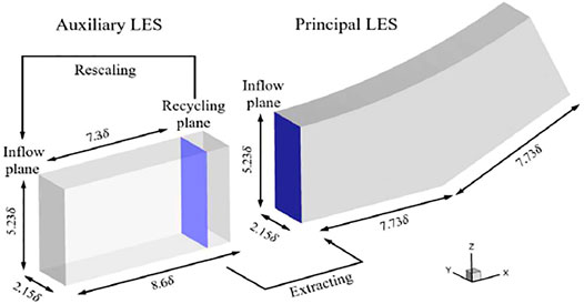
The inlet boundary layer thickness
For the primary computation domain, the upper boundary of the computational domain and the outlet are set to the subsonic outlet boundary condition. The wall condition of the non-slip isothermal is adopted to the wall, and the wall isothermal temperature is 307 K. The spanwise boundary adopts periodic boundary condition, and the inlet turbulent boundary conditions are dynamically given by the auxiliary computation. For the auxiliary computation, the boundary layer conditions are consistent with the main computation, and the flow Mach number is
In order to verify the reliability of the LES software, the numerical results of the compression ramp will be compared with the experimental results under the same inlet flow conditions.
3 Result Analysis and Discussion
Figure 2 shows the distribution of the averaged wall pressure and skin friction coefficient along the streamwise direction in the primary computation domain, where the DNS results of Wu et al. (Wu and Martin 2008) and Tong et al. (Tong et al., 2017) and the experimental data of Bookey et al. (Bookey et al., 2005) are also presented for the purpose of comparison. By solving the position where the averaged skin friction coefficient

FIGURE 2. Distribution of averaged wall pressure and skin friction coefficient. (A) Averaged wall pressure. (B) Averaged skin friction coefficient.
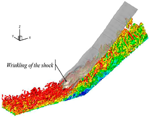
Figure 3 illustrates the instantaneous flow structure in the compression ramp computation domain. Among them, the quasi-order vortex structure of the turbulent boundary layer is displayed using the Q criterion, and the streamwise direction velocity is used for coloring. The translucent gray surface in the figure is the dimensionless pressure isosurface
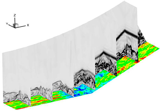
In order to further illustrate the interaction process between the shock wave and turbulent boundary layer, a slice contour in three directions is used to show the flow field details inside the interaction region, as shown in Figure 4. The streamwise and spanwise directions show the numerical schlieren diagram, which is used to show the shock wave, turbulent boundary layer, and flow structure in the separation bubble. It can be seen that the large-scale structure in the interaction region breaks into small-scale structures, which is well agreed with Zhuang Y.et al. (Zhuang et al., 2018b) experimental observation. But, on the slope downstream of the ramp, a large-scale quasi-order structure in the boundary layer is re-established. The instantaneous streamwise direction velocity contour (
3.1 Turbulent Fluctuation
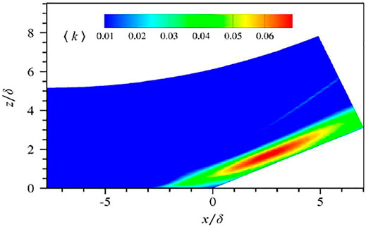
When the flow passes through the interaction region, the turbulent fluctuation is significantly enhanced due to the strong inverse gradient pressure in this region. Figure 5 is a contour of the time-space averaged turbulent kinetic energy. The definition of turbulent kinetic energy is as follows:
Figure 6 presents the variation of Reynolds normal stress

FIGURE 6. Distribution of Reynolds normal stresses at different streamwise locations. (A) Streamwise component. (B) Spanwise component. (C) Wall-normal component.
3.2 Unsteady Motion of Shock Waves
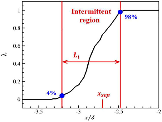
In order to study the shock wave unsteady motion, intermittent factors are usually used to measure the range of shock wave motion along the streamwise direction. The intermittent factor is defined as the time when the instantaneous wall pressure somewhere in the streamwise direction is greater than the given threshold takes up the proportion of the total flow field time. The computation formula is as follows (Dolling and Or 1985):
where
Figure 7 exhibits the local distribution of the intermittent factor in the compression ramp. It is known from the definition of the intermittent factor that in the undisturbed upstream boundary layer and downstream region of the ramp, the intermittent factor is always equal to 0 (or 1). However, in the vicinity of the average separation point, the separation shock wave shows a strong unsteady flow characteristic, which is represented by the intermittent factor:
3.3 Görtler Flow Vortex
From the abovementioned analysis, the supersonic compression ramp flow has significant three-dimensional characteristics. Especially on the slope downstream of the ramp, the flow field shows a strong unevenness in the spanwise direction. This phenomenon is closely related to the presence of Görtler flow vortex (Dolling and Or 1985; Grilli et al., 2013).
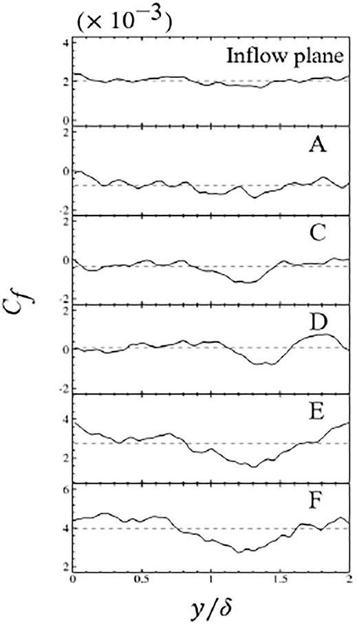
Figure 8 shows a time-averaged skin friction coefficient contour. The white dashed line represents the location of the ramp. The solid black line in the figure is used to show the separation and reattachment positions of the boundary layer near the ramp defined by the time-averaged friction coefficient equal to 0. It can be observed that the skin friction coefficient of the inlet boundary layer represents a strip pattern alternately arranged which is consistent with the spanwise distribution of the time-averaged separation line. This indicates that the distribution of the separation line is, in a great measure, determined by the skin friction coefficient of the inlet boundary layer. Due to the low-frequency pulsation of the separation bubble, the average reattachment still exhibits strong transient flow characteristics. When the separated boundary layer reattaches, the skin friction coefficient distribution appears as an obvious “V” structure, which is caused by the presence of Görtler vortex pairs. The existence of this “V” structure was also confirmed by Fu-Lin et al., (2016).
The formation of Görtler vortices is related to the curvature of the concave surface. In order to describe the spatial development of the Görtler vortex in detail, Figure 9 shows the flow field details on six different sections downstream of the average separation point. These six sections are named A ∼ F, corresponding to the streamwise direction positions:
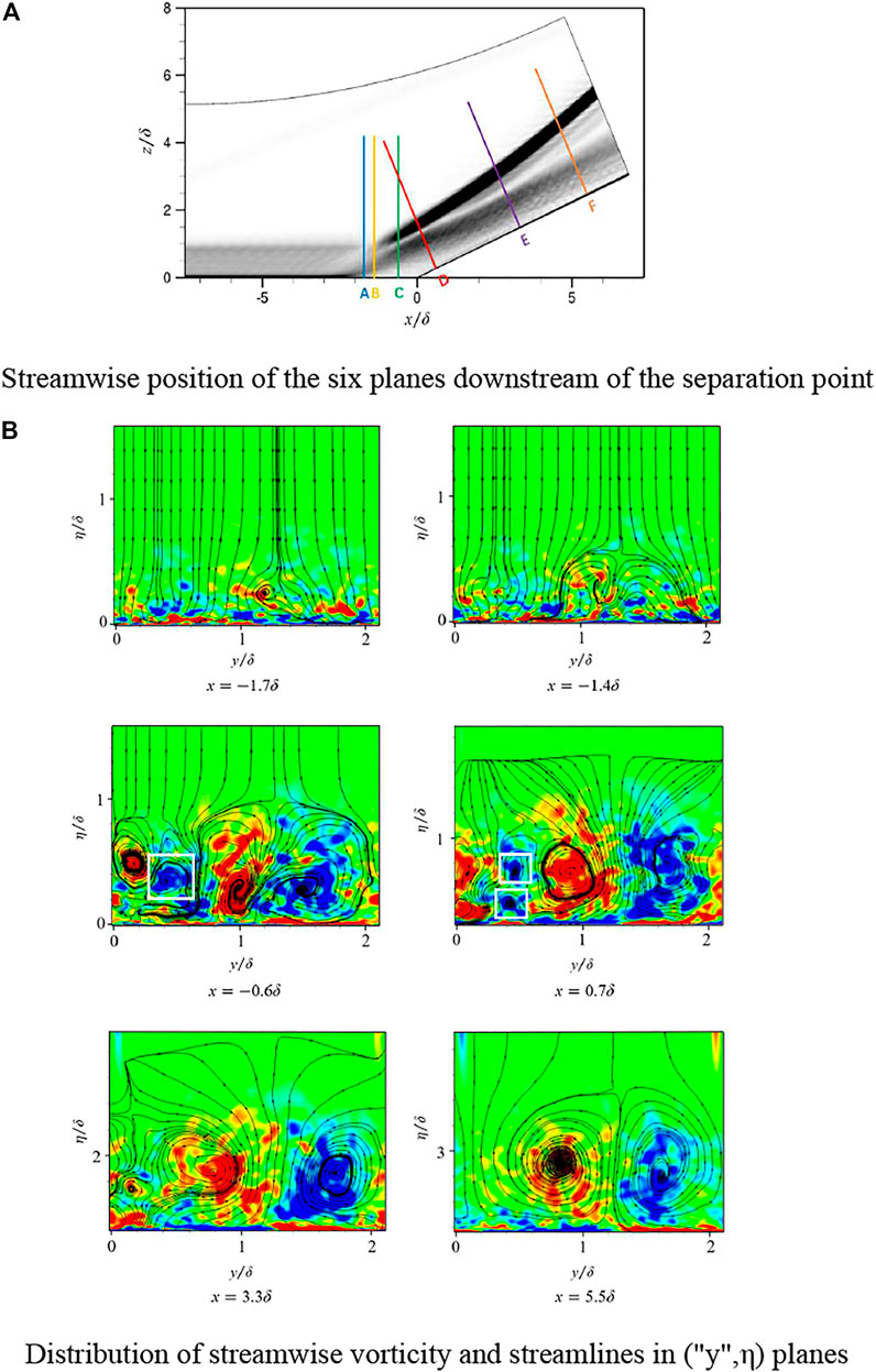
FIGURE 9. Spatial evolution of Görtler-like vortices in the compression ramp. (A) Streamwise position of the six planes downstream of the separation point. (B)Distribution of streamwise vorticity and streamlines in (“y”,η) planes.
Figure 9B illustrates that it can be estimated that the center of the Görtler vortex pair is located at
3.4 Low-Frequency Instability
In order to study the low-frequency motion of the separated shock wave, it is necessary to collect the signal of numerical pressure for spectrum analysis. Therefore, 528 wall pressure probes are arranged along the flow direction in the middle section of the calculation domain. The arrangement of these probes is consistent with the grid distribution, that is, one probe is arranged in the center of each wall grid cell. It is worth noting that the signal acquisition process is carried out after the SWBLI flow field is fully established. In order to ensure sufficient time resolution, data recording is carried out every ten time steps in the large eddy simulation, and the physical time interval between two adjacent recording points is
Figure 11 presents the variation of wall pressure with time at two different positions upstream of the corner (the corner position is
Next, we will make a strict quantitative analysis of the wall pressure fluctuation signal from the perspective of spectral analysis. The Welch method (Barbe et al., 2010) is used to segment the discrete pressure signal, aiming to obtain a smoother and less variance power spectrum density (PSD) curve. In this study, the collected pressure signals are divided into three segments, and the coincidence rate between the segments is 50%. The Hanning window is used to add windows for each segment to improve the variance performance. It should be noted that in the Welch method, the more segmented the data, the smoother the power spectrum curve and the smaller the noise, but at the same time, the resolution of the power spectrum will be affected. Therefore, in the process of data segmentation, we must consider the balance of noise and resolution in the power spectrum curve. Figure 11B shows the PSD distribution curve corresponding to the abovementioned two wall pressure signals, where the abscissa is the dimensionless frequency proposed by Dussauge et al. (Dussauge et al., 2006), which is defined as
In order to study the distribution of low-frequency instability characteristics in the whole field of the compression corner, Figure 13 shows the distribution of WPSD on all pressure probes. The white solid line is used to represent the position of the average separation point
4 Conclusion
In this study, a large eddy simulation (LES) is conducted to investigate the shock wave and turbulent boundary layer interaction in a 24° compression ramp with an inflow Mach number of
The shock wave/turbulent boundary layer interaction represents some flow structure characteristics. When the large scale vortex passes the root of the shock wave, the shock wave surface wrinkles due to the intermittence of the large-scale vortex in the spanwise direction. Under the strong inverse gradient pressure of the compression ramp, the large-scale vortex breaks into a small-scale vortex, the turbulent boundary layer manifests a strong anisotropy characteristic, and the turbulent kinetic energy rapidly increases in the outer layer of the boundary layer downstream of the ramp.
In the region of interaction, the separated shock wave represents an unsteady motion along the streamwise direction. This phenomenon is successfully captured by the intermittent factor. The range of the shock wave motion is
The LES simulation represents a pair of streamwise vortices, called Görtler vortex, occupying almost the entire span width about
The low-frequency instability in the SWBLI is successfully captured by using the power spectrum analysis method. The corresponding characteristic frequency is
Data Availability Statement
The raw data supporting the conclusions of this article will be made available by the authors, without undue reservation.
Author Contributions
XH, L-XW, and D-DZ contributed to the conception and design of the study. XH provided an idea scheme; XH, L-XW, and D-DZ coded; XH analyzed; and NG and l wrote the first draft. All authors contributed to manuscript revision and read and approved the submitted version.
Conflict of Interest
Author XH was employed by the company AECC HUNAN Aviation Powerplant Research Institute.
The remaining authors declare that the research was conducted in the absence of any commercial or financial relationships that could be construed as a potential conflict of interest.
Publisher’s Note
All claims expressed in this article are solely those of the authors and do not necessarily represent those of their affiliated organizations, or those of the publisher, the editors and the reviewers. Any product that may be evaluated in this article, or claim that may be made by its manufacturer, is not guaranteed or endorsed by the publisher.
References
Adams, N. A. (2000). Direct Simulation of the Turbulent Boundary Layer along a Compression Ramp at M = 3 and Re=1685. J. J. Fluid Mech. 420 (1), 47–83. doi:10.1017/S0022112000001257
Barbe, K., Pintelon, R., and Schoukens, J. (2010). Welch Method Revisited: Nonparametric Power Spectrum Estimation via Circular Overlap. J. IEEE Trans. Signal Process. 58 (2), 553–565. doi:10.1109/TSP.2009.2031724
Bookey, P., Wyckham, C., and Smits, A. (2005). New Experimental Data of STBLI at DNS/LES Accessible Reynolds Numbers. Reno: 43rd AIAA Aerospace Sciences Meeting and Exhibit. doi:10.2514/6.2005-309
Dolling, D. S. (2001). Fifty Years of Shock-Wave/boundary-Layer Interaction Research - what Next? AIAA J. 39 (8), 1517–1531. doi:10.2514/3.14896
Dolling, D. S., and Or, C. T. (1985). Unsteadiness of the Shock Wave Structure in Attached and Separated Compression Ramp Flows. J. Experiments Fluids 3 (1), 24–32. doi:10.1007/BF00285267
Dupont, P., Haddad, C., and Debieve, J. F. (2006). Space and Time Organization in a Shock-Induced Separated Boundary Layer. J. Fluid Mech. 559, 255. doi:10.1017/S0022112006000267
Dussauge, J. P., Dupont, P., and Debiève, J. F. (2006). Unsteadiness in Shock Wave Boundary Layer Interactions with Separation. J. Aerospace Sci. Tech. 10 (2), 85–91. doi:10.1016/j.ast.2005.09.006
Floryan, J. M. (1991). On the Görtler Instability of Boundary Layers. J. Prog. Aerospace Sci. 28 (3), 235–271. doi:10.1016/0376-0421(91)90006-P
Fu-Lin, Ton., Tang, Zhi-Gong., and Xin-Liang, Li. (2016). Direct Numerical Simulation of Shock-Wave and Transitional Boundary Layer Interaction in a Supersonic Compression Ramp. J. Chin. J. Aeronautics 37 (12), 3588–3604. doi:10.7527/S1000-6893.2016.0096
Ganapathisubramani, B., Clemens, N., and Dolling, D. (2007). Effects of Upstream Coherent Structures on Low-Frequency Motion of Shock-Induced Turbulent Separation. Reno: 45th AIAA Aerospace Sciences Meeting and Exhibit. doi:10.2514/6.2007-1141
Germano, M. (1991). A Dynamic Subgrid-Scale Eddy Viscosity Model. Phys. Fluids A 3, 1760–1765. doi:10.1063/1.857955
Grilli, M., Hickel, S., and Adams, N. A. (2013). Large-Eddy Simulation of a Supersonic Turbulent Boundary Layer over a Compression–Expansion Ramp. J. Int. J. Heat Fluid Flow 42 (8), 79–93. doi:10.1016/j.ijheatfluidflow.2012.12.006
Lee, C. B., and Wang, S. (1995). Study of the Shock Motion in a Hypersonic Shock System/turbulent Boundary Layer Interaction. Experiments in Fluids 19 (3), 143–149. doi:10.1007/BF00189702
Loginov, M. S., Adams, N. A., and Zheltovodov, A. A. (2006). Large-eddy Simulation of Shock-Wave/turbulent-Boundary-Layer Interaction. J. J. Fluid Mech. 565 (1), 135–169. doi:10.1017/S0022112006000930
Pasquariello, V., Hickel, S., and Adams, N. A. (2017). Unsteady Effects of Strong Shock-Wave/Boundary-Layer Interaction at High Reynolds Number. J. J. Fluid Mech. 823 (1), 617–657. doi:10.1017/jfm.2017.308
Sasaki, K., Barros, D. C., Andre, V., and Cavalieri, G. (2021). Causality in the Shock Wave/turbulent Boundary Layer Interaction. J. Phys. Rev. Fluids 6 (6), 064609. doi:10.1103/PhysRevFluids.6.064609
Settles, G. S., Fitzpatrick, T. J., and Bogdonoff, S. M. (1979). Detailed Study of Attached and Separated Compression Corner Flowfields in High Reynolds Number Supersonic Flow. AIAA J. 17 (6), 579–585. doi:10.2514/3.61180
Shu, C. W., and Osher, S. (1989). Efficient Implementation of Essentially Non-oscillatory Shock-Capturing Schemes. J. J. Comput. Phys. 77 (2), 439–471. doi:10.1016/0021-9991(88)90177-5
Smits, A. J., and Muck, K.-C. (1987). Experimental Study of Three Shock Wave/Turbulent Boundary Layer Interactions. J. Fluid Mech. 182 (182), 291. doi:10.1017/S0022112087002349
Tong, F., Yu, C., and Tang, Z. (2017). Numerical Studies of Shock Wave Interactions with a Supersonic Turbulent Boundary Layer in Compression Corner: Turning Angle Effects. J. Comput. Fluids 149, 56–69. doi:10.1016/j.compfluid.2017.03.009
Touber, E., and Sandham, N. D. (2009). Large-Eddy Simulation of Low-Frequency Unsteadiness in a Turbulent Shock-Induced Separation Bubble. J. Theor. Comput. Fluid Dyn. 23 (2), 79–107. doi:10.1007/s00162-009-0103-z
Touber, E., and Sandham, N. D. (2011). Low-order Stochastic Modelling of Low-Frequency Motions in Reflected Shockwave/boundary-Layer Interactions. J. Fluid Mech. 671, 417. doi:10.1017/S0022112010005811
Wang, Bo. (2015). The Investigation into the Shock Wave/boundary-Layer Interaction Flow Field Organization. Changsha: Graduate School of National University of Defense Technology.
Wu, M., and Martin, M. P. (2008). Analysis of Shock Motion in Shockwave and Turbulent Boundary Layer Interaction Using Direct Numerical Simulation Data. J. J. Fluid Mech. 594 (594), 71–83. doi:10.1017/S0022112007009044
Wu, Yu., Shi-He, Yi., and Chen, Zhi. (2013). Experimental Investigations on Structures of Supersonic Laminar/turbulent Flow over a Compression Ramp. J. Acta Phys. 62 (18), 308–319. doi:10.7498/aps.62.184702
Zhong, Dong-Dong., WangXu, Li., and Ge, Ning. (2021). Reflected Shock/Boundary Layer Interaction Structure Analysis Based on Large Eddy Simulation. Chin. J. aeronautics 34 (5), 364–372. doi:10.1016/j.cja.2020.12.009
Zhu, J., and Qiu, J. (2017). A New Type of Finite Volume WENO Schemes for Hyperbolic Conservation Laws. J. Sci. Comput. 73 (2-3), 1338–1359. doi:10.1007/s10915-017-0486-8
Zhuang, Yi., Tan, Hui-Jun., Li, Xin., Guo, Yun-Jie., and Sheng, Fa-Jia. (2018). Evolution of Coherent Vertical Structures in a Shock Wave/turbulent Boundary-Layer Interaction Flow, Phys. Fluids 30, 111702. doi:10.1063/1.5058278
Keywords: shock wave/turbulent boundary layer interaction, large eddy simulation (LES), low-frequency instability, Görtler-like vortex, power spectrum analysis (PSA)
Citation: Huang X, Wang L-X, Zhong D-D and Ge N (2022) Unsteady Motion of Shock Wave for a Supersonic Compression Ramp Flow Based on Large Eddy Simulation. Front. Energy Res. 10:854019. doi: 10.3389/fenrg.2022.854019
Received: 13 January 2022; Accepted: 10 February 2022;
Published: 07 March 2022.
Edited by:
Lei Luo, Harbin Institute of Technology, ChinaReviewed by:
Fangfei Ning, Beihang University, ChinaHu Wu, Northwestern Polytechnical University, China
Copyright © 2022 Huang, Wang, Zhong and Ge. This is an open-access article distributed under the terms of the Creative Commons Attribution License (CC BY). The use, distribution or reproduction in other forums is permitted, provided the original author(s) and the copyright owner(s) are credited and that the original publication in this journal is cited, in accordance with accepted academic practice. No use, distribution or reproduction is permitted which does not comply with these terms.
*Correspondence: Ning Ge, Z2VuaW5nQG51YWEuZWR1LmNu
 Xing Huang1