- 1School of Petroleum Engineering, Xi’an ShiYou University, Xi’an, China
- 2Scientific Research Institute of Petroleum Exploration and Development of CNPC, Beijing, China
- 3The Third Gas Production Plant of Changqing Oilfield of CNPC, Wushenqi, China
- 4Oil and Gas Technology Research Institute, Changqing Oilfield, Xi’an, China
Carbon dioxide is a typical kind of greenhouse gases, and the oil and gas field recovery ratio could be significantly improved by injecting it into the formation. The main goal is to increase the recovery ratio in the early stage of studying gas injection miscible flooding. With the advancement of the “carbon neutral” strategy in China, the application of CO2 miscible flooding technology, which aims to enhance the oil recovery ratio in Chinese oilfields, has been further expanded. The development concept needs to change from simply improving the recovery ratio to improving both the recovery ratio and the CO2 storage ratio. In the current CO2 flooding research, people mainly focus on the improvement of the recovery factor, and less attention is paid to the underground storage of CO2. In order to further study the relationship between the displacement efficiency of CO2 and the storage situation, this paper innovatively combines the storage ratio and storage amount of CO2 with the recovery factor. A number of parameters under different injection methods in the study area were calculated, providing a new research angle for the study of CO2 displacement. Take Chang 8 reservoir in Block H of Ordos Basin as an example. Firstly, the minimum miscibility pressure (MMP) of CO2 at formation temperature was measured by the slim tube experiment according to the reservoir pressure status to judge the CO2 flooding status in the study area. Then, the numerical simulation model of the study area was established, and the historical fitting was completed according to the existing CO2 flooding test wells. The reservoir numerical simulation is used to study the recovery ratio and CO2 storage ratio under different CO2 miscible flooding, including different injection rates, injection sequences, and bottom hole pressures. The results show that the MMP of CO2 in the study area is between 12.65 and 14.80 MPa, which means the CO2 flooding state in this area is miscible flooding with high oil displacement efficiency. The CO2 storage ratio at 5–40 t/d CO2 injection rate is between 54.02% and 64.38% after 20 years, and the CO2 storage ratio is larger when the gas injection rate is 10 t/d. In combination with CO2 storage capacity and the oil recovery factor, it is recommended that the gas injection rate of a single well in the study area is 20–30 t/d. The CO2 storage ratio after 20 years under different gas injection sequences is 57.69%–61.27%. It is suggested that the study area should be injected with water and gas alternately after 2 years of gas injection. When continuous gas injection is used, the CO2 storage ratio under different production well bottom hole pressures is between 54.95% and 59.82%. It is recommended that the bottom hole flow pressure in the study area be maintained at between 9 and 10 MPa. The results show that the main factor that affects the annual CO2 storage ratio in the study area is the CO2 injection rate. Gas injection rate, injection sequence, and bottom hole pressure of production wells will all have an impact on the overall storage ratio. And alternate water and gas injection is quite significant. From the perspective of storage ratio, the optimal CO2 miscible flooding injection method has been optimized for the study area, which provides a reference for the implementation of CO2 underground storage technology in mines.
Introduction
With the continuous development and progress of modern industrial technology, the use of primary energy such as oil, natural gas, and coal has been increasing, resulting in high global carbon emissions. Due to China’s vast land area and continuous deepening of modernization, its carbon emissions in 2020 will rank second in the world after the United States, which is inconsistent with China’s strategic thinking on sustainable development. Therefore, how to deal with carbon dioxide and other greenhouse gases has become the focus of attention (Global, 2018; I (2017). The Global, 2017). Carbon capture, utilization, and storage (CCUS) is one of the main methods to deal with greenhouse gases (BACHU, 2015), and carbon dioxide miscible flooding is one of the key technologies. On the one hand, it can improve the oil recovery of oil reservoirs, and on the other hand, it can store a large amount of CO2 underground to achieve a win-win situation for environmental protection and economic benefits (Jablonowski and SINGH, 2010; HU et al., 2018a).
According to the oil displacement mechanism, CO2 flooding can be divided into three types: miscible flooding, near-miscible flooding, and immiscible flooding. Miscible flooding has the most obvious displacement effect on crude oil (GOZALPOUR et al., 2005; KOOTTUNGAL, 2014; HU et al., 2018b; HOSSEINI et al., 2018). This is because CO2 and crude oil can effectively improve the viscosity index and gravity override under miscible conditions, thereby increasing the sweep coefficient; the interfacial tension of CO2 and crude oil disappears, the capillary force disappears, and the theoretical oil washing efficiency can reach 100% (BOOTH, 2010; Abedini et al., 2015). An important parameter in CO2 miscible flooding is the MMP (LIAO et al., 2014; Yang et al., 2019; Zareieshirazani and Behbahani, 2019). At present, there are many methods to determine the MMP, which can be divided into experimental methods and theoretical calculation methods. Experimental methods include classic slim tube test, bubble lifting apparatus, interfacial tension loss, etc. (Flock and Nouar, 1984; Rao and Lee, 2002; Zhang and Gu, 2016). Theoretical calculation methods include the empirical formula method, equation of state method, system analytical method, etc. (Yao, 2019). The slim tube experiment is usually used as a standard method to determine the MMP because of its reliable experimental results (Guangying, 2016).
Jahangiri and Zhang (2011) calculated the final recovery ratio and NPV of the reservoir under different CO2 injection methods by commercial numerical simulation software combined with a net present value (NPV) calculation model. The results proved that the recovery ratio and economic benefits of CO2 miscible flooding are greater than those of immiscible flooding. Torabi et al. (2012) evaluated the degree to which the oil recovery ratio is improved by the process of miscible, near-miscible, and immiscible CO2 huff and puff in a single matrix fracture system. They used a saturated light oil component simulator to conduct core analysis of CO2 huff and puff experiment to understand the effects of MMP and injection pressure on recovery ratio.
Zhang et al. (2008) conducted a numerical simulation comparative study on nine injection-production schemes of CO2 flooding reservoirs through commercial software and evaluated the feasibility of CO2 flooding in the study area. Their research aimed at the maximum oil recovery factor and did not consider the CO2 displacement form. Iogna et al. (2017) developed an extended black oil model based on the black oil model and performed an actual simulation with a gas reservoir in the South China Sea. The results are consistent with the complex establishment and complicated calculations of the component model. The sensitivity analysis of CO2 injection rate, reservoir initial pressure, and permeability to gas reservoir recovery factor was carried out. Liao et al. (2013) used low-permeability reservoirs in the eighth district of Xinjiang Oilfield as the research object, established a numerical simulation model, and analyzed the feasibility of the development plan by using commercial software to optimize development methods and gas injection parameters. Different from the traditional water–gas alternation, Cho et al. (2021) proposed the component model of CO2 and CH4 alternation injection and evaluated the reservoir recovery factor and CO2 storage ratio under different injection ratios and injection rates. Pranesh (2018) proposed a method to quantify the CO2 storage ratio of tight and shale gas reservoirs by the gas retention model and conducted sensitivity evaluation of different injection pressures, injection times, and fracture conductivity for recovery ratio. The results showed that injection pressure has the greatest influence on recovery and water–gas exchange is a proper way of CO2 flooding. Ma et al. (2015) used experimental methods to reach similar conclusions. They conducted CO2 flooding experiments on cores of low-permeability reservoirs. The experimental results showed that the injection rate, injection pressure, temperature, and other factors all have an impact on the oil recovery factor, and the injection pressure is the biggest influence factor. Maneeintr et al. (2017) used commercial software to evaluate the CO2 storage volume, reservoir pressure, and swept radius of the reservoir when the CO2 injection rate is 1,000, 2,000, 3,000, and 4,000 t/d. The results showed that the maximum amount of CO2 is stored under the condition of an injection rate of 1,000 t/d. Peck et al. (2018) gave a CO2 storage factor calculation model combined with the Michaelis–Menten calculation model and performed numerical simulations on 12 reservoir models with different depths and lithologies. The results proved that the storage of CO2 is also related to reservoir depth (reservoir temperature and pressure) and lithology (clastic rock and carbonate rock). Guo et al. (2019) analyzed the effects of natural fractures, diffusion phenomena, gas injection methods, etc. on CO2 storage volume in the study block through the long core experiment of CO2 flooding and the method of reservoir numerical simulation. Biagi et al. (2016) combined genetic algorithm and numerical solver to accurately obtain the CO2 recovery factor and optimize the CO2 injection rate. Chasset et al. (2011) simulated four scenarios by quantifying the influence of uncertain hydraulic parameters and formation on CO2 storage, and the results showed that formation uncertainty has a major impact on CO2 storage.
As shown in Table 1, scholars have made a lot of attempts and demonstrations on the characterization of CO2-driven oil and gas reservoir recovery and storage capacity and have achieved fruitful results. However, in the process of CO2 storage calculation, the displacement state of CO2 is rarely considered, which is not conducive to the study of the relationship between CO2 displacement efficiency and storage ratio. Furthermore, many of the CO2 flooding studies conducted in the characterization studies are only to demonstrate the feasibility of the method or simply calculate the recovery factor or storage volume of CO2 flooding, which limits the CO2 storage research to the level of theoretical research. Mine evaluation cannot be effectively combined with multiple parameters. In this paper, the CO2 miscible displacement condition with high displacement efficiency is innovatively introduced into the CO2 storage process, which is beneficial to the demonstration of the relationship between CO2 displacement efficiency and CO2 storage. First, the MMP experiment of crude oil in Chang 8 reservoir in Block H, Ordos Basin, was carried out, and then numerical simulation was used to calculate CO2 storage ratio and recovery rate under different injection modes under the CO2 miscible flooding state. The injection-production method and production parameters from the comprehensive perspective of CO2 storage ratio, CO2 storage capacity, and recovery factor were innovatively optimized, and suggestions for the subsequent development of the block and the environmental protection of CO2 miscible flooding. illustration are provided. Finally, limitations of this research and prospect in terms of the domain are discussed to the best of our knowledge, and several key insights are drawn.
Overview of Chang 8 Reservoir in H Block
Geological Features
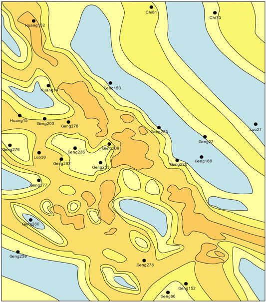
Chang 8 oil reservoir in Block H of the Ordos Basin is located in Fengdikeng Township, Dingbian County, Shaanxi Province, and belongs to a low-permeability oil field. The reservoir mainly has seven channels of different sizes to control its depositional distribution characteristics, and a set of meandering river delta plains and frontal sedimentary subfacies have developed. The boundary between the plain subfacies and the front subfacies is set at the line of Huang 36–Huang 39–Chi 36–Chi 41–Yuan 172. Through a fine reservoir comparison, it is found that there are large structural gaps in some areas, and faults are inferred, which have been verified by seismic profile and water drive front edge tests. Judging from the imaging log, the scale of fracture development in this area is not large, and the degree of fracture development in the reservoir section is relatively low. The direction of the maximum horizontal principal stress is northeast east to southwest, and the anisotropy is generally strong due to the difference in the ground stress of Chang 8 formation. The distribution of sand bodies is shown in Figure 1. The width of the sand body is 35 km, and the distribution is stable in the vertical and horizontal directions. However, the heterogeneity of reservoir is strong, and the difference between layers is great.
Reservoir Characteristics
The lithology of Chang 8 reservoir in Block H of the Ordos Basin is mainly fine sandstone, medium-fine sandstone, and silt-fine sandstone. The mineral composition is mainly lithic feldspar sandstone and feldspar sandstone, followed by feldspar lithic sandstone and lithic sandstone. Composition and structure maturity are medium-good. The pore structure is dominated by intergranular pores with small pores and fine throats, feldspar pores, and lithic pores. From top to bottom, it can be subdivided into four layers: Chang811, Chang812, Chang821, and Chang822. Among them, Chang 811 is the main reservoir group with well-developed sand body and good reservoir physical property. The buried depth of the oil reservoir is 2,600 m, the average sand body thickness is 17.5 m, the oil layer thickness is 15.7 m, the porosity is 8.3%, the permeability is 0.53 × 10⁻³ μm2, the average porosity is 3.3%, and the average pore size is 10–120 μm, which is a typical low-porosity–ultra-low-porosity, low-permeability–ultra-low-permeability reservoir. The original pressure of the reservoir is 18.2–22.6 MPa.
Reservoir Development Characteristics
The data at the early stage of development of this reservoir show that the oil–water distribution relationship of Chang 8 is relatively complicated, and most of the test well sections contain oil and water. In Chang 8 oil reservoir, not only does the high part of the structure produce water or both oil and water, but also the low part of the structure produces oil, and even the high part produces water but no oil, but the low part produces oil. This is a unique phenomenon of Yanchang Formation low-permeability and ultra-low-permeability oil reservoirs. Because the reservoir is tight, oil and water cannot be differentiated. The reservoir is controlled by lithology (sand body) and physical prop.
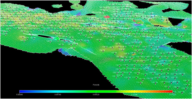
In the early stage of development, the reservoir was developed by water injection, but the contradiction was more prominent. (1) Affected by the heterogeneity between layers, the contradiction of the water absorption profile is prominent, and the degree of water driving is low. (2) The uneven distribution of reservoir physical properties leads to low pressure retention in local areas and high pressure and low production wells. (3) Local fractures are developed, and it is difficult to treat water breakthrough wells. In March 2020, there are a total of 387 wells in the reservoir, including 270 production wells and 117 water injection wells. The well location distribution map is shown in Figure 2. Since Chang 8 oil reservoir in Block H of the Ordos Basin is a typical tight oil reservoir and the heterogeneity of the reservoir is strong, the effect of traditional water injection development on the oil reservoir is not very obvious. Consider other approaches to development later. Due to the local micro fractures developed in the reservoir, the CO2 miscibility-driven method can be used to further develop the reservoir.
Research on MMP of Chang 8 Reservoir in Block H
The MMP is a key indicator to determine whether CO2 and formation crude oil can be miscible. There are four main experimental methods for determining the MMP: slim tube test, bubble lifting apparatus, interfacial tension loss, and interfacial tension disappearance method. It is generally believed that the slim tube test can give accurate results with repeatability, and it is the current method for determining the MMP at home and abroad.
Experimental Steps
The exact MMP of the sample is determined by the slim tube test, and the experimental device diagram is shown in Figure 3.
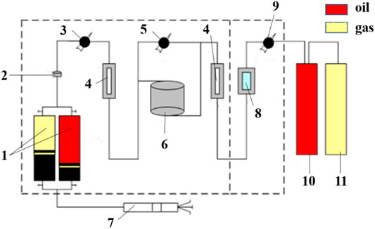
FIGURE 3. Flow chart of slim tube text. 1: Intermediate container; 2: Filter; 3: Injection pressure gauge; 4: Observation window; 5: Differential pressure gauge; 6: Slim tube; 7: Injection pump; 8: Pressure regulator; 9: B Back pressure gauge; 10: Liquid meter; 10: Gas meter.
The experimental operation process is as follows: ① After installation of the experimental system, use the pump drawer to vacuum state, adjust the temperature of the thermostatic control box to the formation temperature and the pressure to the formation pressure, at the same time saturate the crude oil in the slim tube, and then fill the intermediate container for displacement gas sample and to keep the balance. ② Utilize the back pressure regulator to control the back pressure and adjust the pressure to the pressure value required by the experiment. ③ Use the American Ruska automatic injection pump to displace the gas sample to 1.2 times the pore volume (HCPV) at a constant rate of 0.12 ml/min; the entire displacement process is ended. ④ The produced oil sample is measured by an automatic liquid collector at regular intervals, and the produced gas is measured with an automatic gas meter. ⑤ Choose different pressures and repeat the above steps; generally, select six pressure points, three miscible pressures or more, and three miscible pressures or less. ⑥ Calculate the recovery factor and draw the relationship curve between pressure and recovery ratio. The pressure corresponding to the inflection point of the curve is the MMP.
In order to make the measured MMP as close as possible to that of Chang 8 reservoir in Block H of Ordos Basin, 19 groups of experiments were carried out. The 19 oil samples are from wells in different areas of Chang 8 reservoir in Block H of the Ordos Basin, with different basic parameters such as density, composition, and temperature. Before each experiment, the slim tube must be thoroughly cleaned with petroleum ether. The cleaning is completed when the petroleum ether injected from the inlet of the slim tube is the same color and composition as the petroleum ether flowing out of the outlet of the slim tube. Generally, the slim tube needs to be cleaned at least three times. After the cleaning is completed, the clean slim tube is dried with nitrogen and placed in an oven for more than 6 h at the same time. After the slim tube is dried, the porosity and permeability are measured, and the pore volume PV is calculated.
Experimental Materials
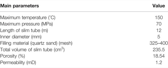
The parameters of the slim tube model used are shown in Table 2.
The preparation process of the formation crude oil sample for the experiment is as follows. ① Put an appropriate amount of ground degassed oil into the sample cylinder, seal and heat it to the formation temperature, and stabilize it for about 4 h. ② After the temperature becomes stable, calculate the gas sample dosage according to the weight of the loaded oil sample and the original dissolved gasoline ratio. ③ Inject the required gas sample into the sample cylinder, pressurize it to the formation pressure, maintain the formation temperature and pressure, fully stir, make it a single phase, and stabilize it for more than 4 h. ④ Determine the saturation pressure and gas–oil ratio of the compound crude oil. If the saturation pressure differs greatly from the actual saturation pressure of the formation oil, adjust the dissolved gas volume of the oil in the sample cylinder until the measured saturation pressure and dissolved gas–oil ratio are the same or similar to those of the original formation oil.
Results and Analysis
At the experimental temperature (58.9°C) and the predetermined displacement pressure (9, 11, 13, 15, 17, and 19 MPa), the CO2 gas is injected at a constant rate of 0.12 ml/min to displace the sample 1 formation oil in the slim tube model. Every time a certain amount of CO2 is injected, collect and measure the volume of output oil and gas and record pump readings, injection pressure, and back pressure. Observe the fluid phase and color changes through the high-pressure observation window. After the cumulative injection of 1.2 times the pore volume of CO2, the displacement is stopped, and the crude oil production in the slim tube is calculated. Figure 4 shows the relationship curve between the pressure of sample 1 and the recovery ratio. The pressure corresponding to the inflection point of the curve is the MMP.
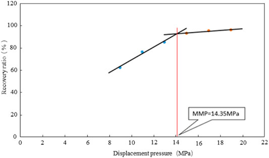
FIGURE 4. The relationship between the CO2 displacement recovery ratio and displacement pressure in the slim tube test of sample 1.
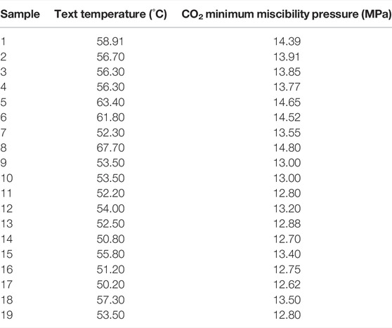
From Figure 4, it can be seen that the MMP of formation crude oil sample 1 at a temperature of 58.9°C is 14.35 MPa for carbon dioxide flooding. Continue to perform the same steps to obtain the CO2 MMP of other samples as shown in Table 3.
From the results of the slim tube test, it can be seen that the miscible pressure of CO2 and crude oil in Chang 8 reservoir in Block H is between 12.65 and 14.80 MPa, which is lower than the original formation pressure of 18.2–22.6 MPa. In the subsequent gas injection development process, the injection of gas or liquid will also supplement the formation energy to ensure the stable miscible flooding of CO2 underground. Therefore, the subsequent CO2 injection development can achieve miscible flooding. On the one hand, it effectively improves the recovery of crude oil. On the other hand, CO2 can be dissolved into the residual oil of the oil reservoir as much as possible to realize the underground storage of CO2.
Research on CO2 Storage Ratio Under Different Injection Methods in the Study Area
Oil exploitation is characterized by a complex physicochemical process and dynamic parameters. Therefore, the developed production test methods are often unable to accurately predict the changes in future production data and parameters of oil and gas reservoirs and have certain limitations. With the rapid development of computing technology in recent years, some partial differential equations that are traditionally considered to be unsolvable have been numerically solved with the aid of computers. As a result, the numerical simulation method has become a very important and commonly used technology for oil and gas reservoir development. This paper established the numerical simulation model and carried out the simulation calculation of CO2 storage ratio.
Model History Matching and the Calculation Method of CO2 Storage Ratio
Geological software PETREL was used to establish the 3D model. According to the spacing of horizontal well pattern and the distribution frequency of sand body thickness in the working area, the geometric size of the grid was defined as 20 × 20 m. The current four layer groups, Chang811, Chang812, Chang821, and Chang822, were divided into 115 grids vertically, and the height of each longitudinal grid was controlled between 0.5 and 1 m. The original discrete point data of the reservoir structure model came from the formation comparison of well logging interpretation. Lithofacies modeling mainly uses sequential indicator simulation methods for simulation. The reservoir parameter model refers to the three-dimensional spatial distribution of parameters such as porosity, permeability, and oil saturation reflecting the physical properties, lithofacies, and oil content of the reservoir. It is performed based on drilling data, logging data, core analysis data, and production performance data. There are 270 production wells and 117 water injection wells.
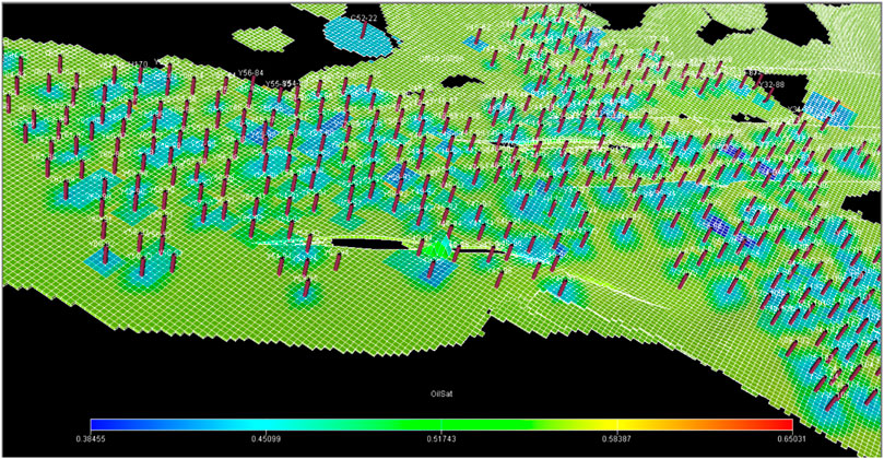
The entire reservoir in the study area is conventional oil. Taking into account the accuracy of CO2 calculation and the geological reservoir characteristics of the study area, this paper selects the E300 component simulation module of Schlumberger’s Eclipse simulation software for simulation calculation. In the process of oil reservoir history fitting, the relative error of static reserves fitting is controlled within −1% to 3%. The initial pressure of the reservoir is also fitted to the production data. The fitting ratio of the whole area and single well has reached more than 90%. The remaining oil distribution of Chang 8 reservoir in Block H is mainly affected by lithology, development well pattern, sand body edges, structures, and faults. The current remaining oil saturation distribution in the simulation area is shown in Figure 5.
The annual storage ratio and total storage ratio of CO2 in this paper are calculated by the following formula:
SRa: Annual storage ratio of CO2,%;EVa: Annual production capacity of CO2, m3;IVa: Annual injection capacity of CO2, m3;SR: Total storage ratio of CO2 during the study period, %;EV: Total production capacity of CO2 during the study period, m3;IV: Total injection capacity of CO2 during the study period, m3.
The CO2 production and injection in the above formulas are derived from the Eclipse software for numerical simulation of commercial reservoirs.
CO2 Storage Ratio Under Different Gas Injection Rates
According to the current development status and reservoir characteristics of Chang 8 reservoir in Block H, five schemes are designed to study the gas injection rate. The production well is produced at a constant bottom hole pressure, and the injection well is injected at a constant injection rate for a total of 20 years of simulation. The gas injection method adopts continuous gas injection, the bottom hole flow pressure of the production well is set to 8 MPa, and the CO2 storage ratio is obtained when the single injection well rate is 5, 10, 20, 30, and 40 t/d.
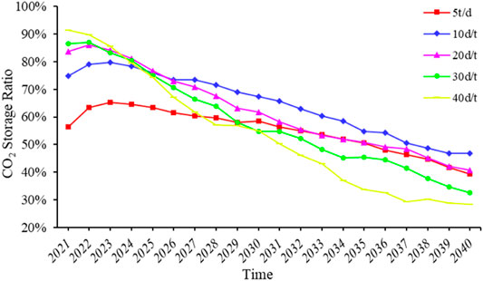
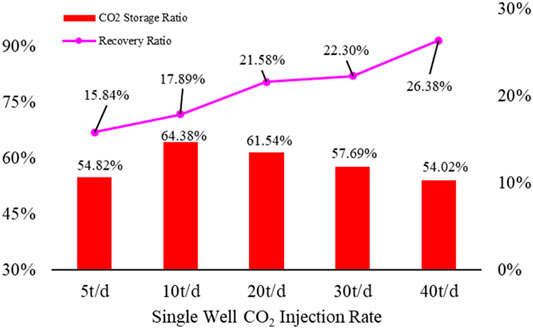
By solving each model, we can get the 20-year CO2 storage ratio under five gas injection rates as shown in Figure 6. The storage ratio of the five schemes in the first 4 years generally showed first an increasing trend and then a decreasing trend. This is because the CO2 has not yet spread to a large enough volume in the first few years after the injection of CO2. The CO2 protrudes into the production well along a small part of the formation, and the contact formation area, formation water, and residual oil volume are small, preventing it from being effectively adsorbed into the formation or dissolved into the fluid. Later, as the formation pressure in the area not affected by CO2 gradually decreased, the CO2 continuously entering the formation spread to a larger volume under the injection pressure, so the annual CO2 storage ratio gradually increased. After that, the increase rate of the swept volume of the reservoir slowed down. As the gas was adsorbed in the reservoir matrix, the dissolved gas in the formation water, irreducible water, and residual oil gradually became saturated, and the CO2 storage ratio decreased significantly. In the comparison of the changes in the annual CO2 storage ratio of the five schemes, it can be seen that the greater the injection rate, the greater the storage ratio in previous years, and the more obvious the subsequent decline in the storage ratio. This is related to the swept volume of injected CO2; the greater the injection rate, the greater the supplementary formation energy; the first area to be reached is larger, and the subsequent swept volume advancing speed slows down. The smaller the injection rate, the lower the supplementary formation energy; the first arriving swept volume is smaller, and the subsequent swept volume increased, where the increasing speed is higher than when the injection speed is large. Accumulating the CO2 storage volume and injection volume over the years can get the 20-year total CO2 storage ratio of the five schemes, as shown in Figure 7. When the injection flow rate of a single well is 5 t/d, the CO2 storage ratio is relatively small, the maximum of 10 t/d is 64.38%, and the storage ratio decreases gradually from 10 to 40 t/d. It is speculated that when the injection volume of a single well is 5 t/d, the supplementary formation energy is small, so the affected volume is the smallest, resulting in a small overall storage ratio. When the injection volume of a single well is 40 t/d, the first part of the affected volume is large, which no longer dissolves or adsorbs CO2, and this part of CO2 returns to the ground, resulting in a small volume of newly contacted CO2 every year after the first 5 years; that is, the spread volume advances slowly. In contrast, when the injection volume of a single well is 10 t/d, the slower the injection rate after the first 5 years, the faster the advancing speed of the swept volume. Therefore, in general, the higher the injection speed, the lower the overall CO2 storage ratio.
It can be seen from Figure 7 that the 20-year final recovery ratio and CO2 storage ratio when the injection volume of a single injection well is 5 t/d are both small. The greater the injection rate from 10 t/d, the greater the recovery factor, which is inversely proportional to the CO2 storage ratio. Therefore, in the follow-up development of the study area, it is recommended to choose a single well with a daily injection rate of 20–30 t/d to ensure the CO2 storage ratio and maximize the oil reservoir recovery factor.
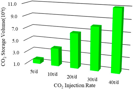
In the comparison of the 20-year CO2 storage volume of the five schemes, as shown in Figure 8, it can be seen that the CO2 injection rate is proportional to the storage volume. The more CO2 injected into the formation, the more CO2 is stored underground. This is because the greater the injection rate, the greater the supplementary formation energy, the greater the volume of the affected formation, and the more CO2 will be adsorbed and dissolved.
The CO2 storage volume and ratio of the five schemes are actually controlled by the volume of CO2 spilled. When the injection rate of a single well is 5 t/d, the swept volume, storage ratio, and storage volume are relatively small. When the injection rate of a single well is greater than 10 t/d, the storage ratio is inversely proportional to the storage volume and directly proportional to the growth rate of the swept volume.
CO2 Storage Ratio Under Different Gas Injection Sequences
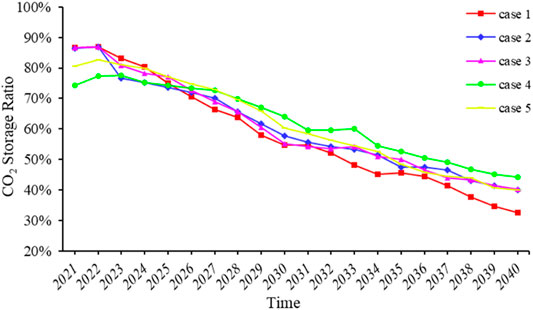
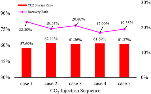
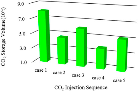
In the actual CO2 flooding process of oil reservoir development, viscosity fingering will affect the swept volume of CO2 flooding. Therefore, the method of alternating gas and water is often used in the production process to effectively reduce the CO2 viscosity fingering and increase the swept volume. The sequence of alternating gas and water injection is also an important factor affecting the CO2 storage ratio. Five schemes were designed to study the sequence of gas injection. The production wells used constant bottom hole pressure for production, and the injection wells used constant injection volume. The bottom hole flowing pressure was set to 8 MPa, and the daily injection rate of the injection well was set to 30 t/d. Five schemes were respectively simulated for 20 years.
Case 1. continuous gas injection;
Case 2. water and gas 1:1 alternate after 2 years of continuous gas injection;
Case 3. water and gas 1:2 alternate after 2 years of continuous gas injection;
Case 4. water and gas 1:1 alternate;
Case 5. water and gas 1:2 alternate.One month is 30 days as an alternate time. The water injection volume of a single well is 35 m3/d.From Figure 9, it can be seen that the storage ratio of the five schemes in the first 4 years also increases first and then decreases, which is the same as the above-mentioned change trend under different injection flow rates. This is because at the beginning, the CO2 rushed from the channel of the previous water flooding, and the affected volume was not large. In the comparison of the annual CO2 storage ratios in Case 1 versus Cases 2 and 3, the CO2 storage ratio coincides in the first 2 years. After 3 years, the annual storage ratio of Cases 2 and 3 are first lower than that of Case 1, and then at 2–3 years, it is greater than that of case 1. This proves that alternate injection of water and gas reduced the viscosity index during CO2 flooding during the subsequent increase in swept volume, so that CO2 can enter a larger displacement volume to complete adsorption or dissolution. The annual storage ratios of Cases 2 and 3 are not much different. Cases 4 and 5 were direct water and gas alternate injection. The CO2 storage ratio in the first 2 years is lower than that of Cases 1, 2, and 3. This is because the formation energy supplemented by water injection was smaller than that of gas injection, and the increase rate of swept volume is smaller. The annual storage ratio of the two cases is not much different, and the annual storage ratio of these two cases is greater than the first three cases after the fifth year. The total CO2 storage ratio can be obtained by adding up the storage volume after 20 years and the injection volume as shown in Figure 10. Case 2 has the largest final storage ratio, 62.11%. It can be seen that the storage ratio of alternate gas and water injection is greater than that of continuous gas injection. This is because, on the one hand, the injection of water reduced the viscosity index of CO2 and, on the other hand, part of the injected water stayed in the formation and increased the dissolved volume of CO2, which had a positive effect on the storage of CO2. At the same time, alternate water injection reduced the injection energy compared to continuous gas injection, which had a negative effect on CO2 storage. The positive effect was greater than the reverse effect in the storage process. Although the injected gas and water volumes are different in Cases 2 and 3, they are similar from the point of view of the total storage ratio. This is similar to the above-mentioned reason for the difference between continuous gas injection and alternate water and gas injection and is caused by the combined effect of positive and negative reasons.The pink broken line in Figure 10 is the oil reservoir recovery change diagram. It can be seen that in Case 1, although the oil field recovery is relatively high, the buried CO2 ratio is low, which does not meet the requirements of buried CO2. Under the same water–gas alternating cycle, the recovery factor and buried CO2 ratio of Cases 2 and 3 in the early continuous cycle are respectively greater than those of Cases 4 and 5. Therefore, in the development process of water–gas alternating injection in the study area, continuous gas injection in previous years should be considered when carrying out water–gas alternating injection.The CO2 storage capacity of the five schemes is shown in Figure 11. Although the storage ratio of case 1 is small, it has the highest amount of CO2 because of the large amount of injected CO2. The final storage ratio of Cases 2–5 is not much different, so the more CO2 that is injected, the more it will be stored. In combination with the previously discussed reservoir recovery and CO2 storage ratio, Case 3 is the best choice for gas injection sequence in the study area.It can be seen from the comparison of storage sequence schemes that alternate water and gas injection is very important during the CO2 injection process, which also proves the effect of water on reducing the viscosity index during the CO2 flooding process. The specific water–gas alternation ratio has little effect on the CO2 storage ratio. However, it has a significant influence on recovery factor and CO2 storage ratio.
CO2 Storage Ratio Under Different Bottom Hole Pressures of Production Wells
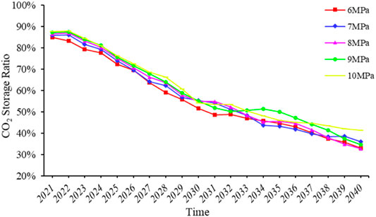
The bottom hole pressure of production wells determines the speed of CO2 and crude oil flowing into the bottom of the well and has an important impact on the volume of CO2 swept. Five schemes were designed to study the bottom hole flow pressure of production wells. The production well was produced at a constant bottom well flow pressure, and the injection well was produced at a constant injection rate, which was simulated for a total of 20 years. The gas injection sequence was continuous gas injection, the daily injection rate of single injection well was 30 t/d, and the bottom hole flow pressure of the production well was set to 6, 7, 8, 9, and 10 MPa, respectively.
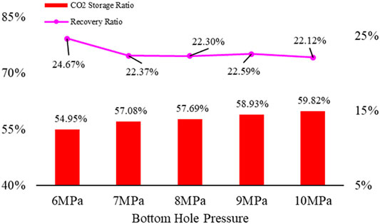
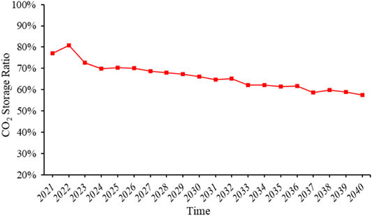
The annual CO2 storage ratio under different bottom hole pressures of production wells is shown in Figure 12. The change trends of the annual storage ratio obtained by the five schemes are relatively similar and generally show a gradual decreasing trend. In the same year, the bottom hole pressure is proportional to the annual storage ratio. This is because when the bottom hole flow pressure was smaller, the pressure differences between injection well and production well and between formation boundary and production well were larger, resulting in the injected CO2 entering the production well too quickly and being unable to contact as many layers as possible, resulting in a low storage ratio. The obtained histogram of accumulated storage in 20 years is shown in Figure 13. The cumulative storage ratio is also proportional to the bottom hole pressure, and the storage ratio varies greatly. When the bottom hole pressure of the production well is 10 MPa, the storage ratio is the largest, reaching 59.82%. As can be seen from the schematic broken line of oil reservoir recovery shown in Figure 13, when the bottom hole flow pressure of the production well is 6 MPa, although the recovery factor is large, the CO2 storage ratio is small. The recovery ratio is similar when the bottom hole flow pressure is 7–10 MPa, but the CO2 storage ratio is significantly different. The recovery ratio is not quite low when the bottom hole flow pressure is 10 MPa, and the CO2 storage ratio is the largest.
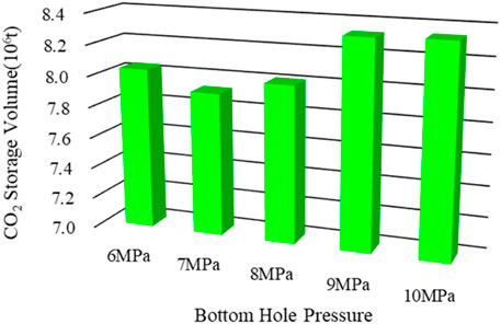
The CO2 storage volume obtained under different production well bottom hole pressures is shown in Figure 14. It can be seen that the storage volume is proportional to the storage ratio. The pressure differences between the production well and the injection well and between the production well and the formation boundary were the smallest when the bottom hole flowing pressure was the largest. Therefore, more injected fluid can contact the reservoir, thereby increasing the swept volume of the reservoir and increasing the storage capacity.
Combining the analysis of the CO2 storage ratio, storage capacity, and oil reservoir recovery factor, CO2 miscible flooding in the study area has the best effect when the bottom hole flow pressure is 9–10 MPa. Thus, it is suggested to choose 9–10 MPa as the bottom hole pressure of production wells for CO2 miscible flooding development in the research area.
The Best CO2 Injection Scheme
The injection parameters of CO2 miscible flooding were optimized through the above steps. The gas injection rate single well 10 t/d, water and gas 1:1 alternate after gas injection for 2 years in injection sequence, and bottom hole flow pressure of production wells 10 MPa at the maximum CO2 buried storage ratio of CO2 miscible flooding in the research area were used for modeling and solving again. The annual CO2 storage ratio obtained is shown in Figure 15. Compared with the above-mentioned experimental schemes, the storage ratio in previous years is not much different, but the storage ratio decline rate under the best injection method is relatively low. The final volume of CO2 stored is 2.40 × 10⁶ t, the reservoir recovery factor is 15.47%, and the final 20-year cumulative CO2 storage ratio reaches 66.88%, which is the largest CO2 storage ratio compared with the above-mentioned schemes.
When we compare the annual CO2 storage ratio of five different gas injection flow rates, five different gas injection sequences, five different bottom hole pressures of production wells, and the best scheme, it can be seen that what is decisive for the change trend is the gas injection rate, and the bottom hole flow pressure and gas injection sequence have relatively little influence, and but they add up to change the overall storage ratio. Therefore, the main controlling factor of the annual CO2 storage ratio is the gas injection rate. Changing the gas injection sequence and bottom hole flow pressure cannot significantly change the annual storage ratio. The overall CO2 storage ratio is related to the gas injection rate, gas injection sequence, and bottom hole pressure of the production wells. The injection rate and the bottom hole pressure have a significant influence on CO2 storage ratio. The gas injection sequence is only higher when the water and gas alternate when the fluid is injected, and there is no high requirement on the alternate ratio. The optimized injection scheme has slowed down the reduction in the annual CO2 storage ratio to a certain extent.
In general, the ultimate purpose of optimizing injection speed and gas injection sequence, or optimizing bottom hole flow pressure, is to increase the sweep volume of CO2 and thus increase the matrix adsorption and dissolution amount of CO2 to realize the increase of CO2 storage ratio. Therefore, in the follow-up study of CO2 storage ratio, the method of increasing the volume of CO2 should be considered.
Limitations and Prospects
It is very meaningful to study the storage potential of CO2 for the current world environmental protection. How to ensure the effective storage of CO2 under the premise of enhancing oil recovery is an important topic discussed by scholars in the petroleum and natural gas industry today. In this study, the production parameters of different injection methods in the CO2 miscible flooding state were used to explore the feasibility of parallel oil recovery and CO2 storage in the process of CO2 injection and development. The relationship between the storage ratio and the storage capacity provides a development plan for the study area that takes into account both the recovery rate and the CO2 storage. However, there are several limitations here, and interested scholars can continue to investigate further. First of all, more parameter improvements are needed, not only limited to the injection rate, injection sequence, and production well flow pressure mentioned in the article itself. In the actual development process of injected CO2 reservoirs, the bottom hole flow pressure of the injection well, the ratio of water, its injection amount when water and gas are alternated, etc. have a great influence on the recovery rate and CO2 storage ratio. In future research, these influencing factors can be factored based on the statistical law of the parameters of different CO2 development methods, directly indicating the degree of influence of these parameters on the recovery factor, CO2 storage ratio, and integrated quantification, so as to provide information for other oil and gas reservoirs. This provides a reference for CO2 injection optimization of other oil and gas reservoirs. Secondly, the displacement mechanism of CO2 miscible flooding and the storage mechanism when CO2 and water are injected alternately need to be further clarified. The commercial software Eclipse used in this paper calculates the sequestration rate of CO2 miscible flooding that keeps CO2 dissolved in water or residual oil and adsorbed on the solid surface. There is no more objective consideration of the complex physical and chemical reactions of CO2 with crude oil and water in the formation at different temperatures and pressures (Gao et al., 2021). It is necessary to propose a more accurate calculation method of CO2 underground storage ratio.
Conclusion
(1) The MMP of the indoor slim tube shows that the MMP of the crude oil in the study area for CO2 is between 12.65 and 14.80 MPa, which is lower than the current formation pressure of 18.2–22.6 MPa. Therefore, miscible flooding can be achieved in the subsequent development of CO2 injection.
(2) To carry out the comprehensive consideration of CO2 storage ratio, storage volume, and oil reservoir recovery factor in the study area, the best gas injection scheme is as follows: the single well gas injection is 20–30 t/d; the gas injection is performed 2 years before the gas injection sequence, followed by alternate water and gas injection; and the bottom hole flow pressure of the production wells is 9–10 MPa.
(3) The gas injection rate will obviously change the change trend of the annual CO2 storage ratio in the study area. The biggest influence on the annual CO2 storage ratio is the fluid gas injection rate. The gas injection sequence and bottom hole flow pressure will not significantly change the annual CO2 storage ratio.
(4) The overall CO2 storage ratio in the study area is significantly related to the gas injection rate, injection sequence, and bottom hole pressure of the production wells. The water–gas alternation is very important, and the specific alternate ratio has little effect on the final CO2 storage ratio.
(5) The key point that affects the CO2 storage ratio in the study area is the CO2 swept volume. The larger the affected volume, the larger the overall CO2 storage ratio and annual storage ratio.
(6) Chang 8 reservoir in Block H of Ordos Basin has good CO2 storage potential, and an optimal CO2 injection scheme has been optimized. After 20 years of CO2 injection, the CO2 storage ratio is up to 66.88%, and the storage volume is 2.40 × 10⁶ t.
Data Availability Statement
The original contributions presented in the study are included in the article/Supplementary Material, further inquiries can be directed to the corresponding author.
Author Contributions
All authors listed have made a substantial, direct, and intellectual contribution to the work and approved it for publication.
Conflict of Interest
BL was employed by the company The Third Gas Production Plant of Changqing Oilfield of CNPC. LS was employed by the company Changqing Oilfield.
The remaining authors declare that the research was conducted in the absence of any commercial or financial relationships that could be construed as a potential conflict of interest.
Publisher’s Note
All claims expressed in this article are solely those of the authors and do not necessarily represent those of their affiliated organizations, or those of the publisher, the editors and the reviewers. Any product that may be evaluated in this article, or claim that may be made by its manufacturer, is not guaranteed or endorsed by the publisher.
References
Abedini, A., Torabi, F., and Mosavat, N. (2015). Performance of Immiscible and Miscible CO2 Injection Process in a Tight Carbonate Reservoir (Experimental and Simulation Approach). Ijogct 9, 265. doi:10.1504/ijogct.2015.068994
Bachu, S. (2015). Review of CO2 Storage Efficiency in Deep saline Aquifers. Int. J. Greenhouse Gas Control. 40, 188–202. doi:10.1016/j.ijggc.2015.01.007
Biagi, J., Agarwal, R., and Zhang, Z. (2016). Simulation and Optimization of Enhanced Gas Recovery Utilizing CO2. Energy 94, 78–86. doi:10.1016/j.energy.2015.10.115
Booth, R. J. S. (2010). On the Growth of the Mixing Zone in Miscible Viscous Fingering. J. Fluid Mech. 655 (15), 527–539. doi:10.1017/s0022112010001734
Chasset, Coralie., Jarsjö, Jerker., Erlström, Mikael., Cvetkovic, Vladimir., and Destouni, Georgia. (2011). Scenario Simulations of CO2 Injection Feasibility, Plume Migration and Storage in a saline Aquifer, Scania, Sweden. Int. J. Greenhouse Gas Control. 5 (Issue 5), 1303–1318. doi:10.1016/j.ijggc.2011.06.003
Cho, Jinhyung., Min, Baehyun., Kwon, Seoyoon., Park, Gayoung., and Lee, Kun. Sang. (2021). Compositional Modeling with Formation Damage to Investigate the Effects of CO2–CH4 Water Alternating Gas (WAG) on Performance of Coupled Enhanced Oil Recovery and Geological Carbon Storage [J]. J. Pet. Sci. Eng. 20, 108795. doi:10.1016/j.petrol.2021.108795
Flock, D. L., and Nouar, A. (1984). Parametric Analysis on the Determination of the Minimum Miscibility Pressure in Slim Tube Displacements [J]. J. Can. Pet. Tech. 23, 80–88. doi:10.2118/84-05-12
Gao, Ran., Lv, Chengyuan., Zhou, Kai., Lun, Zengmin., and Zhou, Bing. (2021). A Calculation Method for CO_2-driven Storage Potential Based on Component Flash Evaporation[J]. Pet. Drilling Prod. Tech. 43 (01), 70–75.
Gozalpour, F., Ren, S. R., and Tohidi, B. (2005). CO2Eor and Storage in Oil Reservoir. Oil Gas Sci. Tech. - Rev. IFP 60 (3), 537–546. doi:10.2516/ogst:2005036
Guangying, Chen. (2016). CO2 Simulation Prediction and Experimental Determination of Minimum Miscibility Pressure with Crude Oil [D]. Changsha: Hunan University.
Guo, Ping., Li, Xuehong., Sun, Zhen., Wang, Shaofei., and Du, Jianfen. (2019). Numerical Simulation of CO_2 Flooding and Storage in Low-Permeability Gas Reservoirs[J]. Sci. Tech. Eng. 19 (23), 68–76. doi:10.1016/j.proenv.2011.12.221
Hosseini, S. A., Alfi, M., and Nicot, J. P. (2018). Analysis of CO2 Storage Mechanisms at a CO2-EOR site,Cranfield,Misssippi [J]. Greenhouse Gases Science& Tech. 8 (3), 569–482. doi:10.1002/ghg.1754
Hu, Wei., LOChengyuan, , and Wang, Rui., (2018). Porous Flow Mechanisms and Mass Transfer Characteristics of CO2miscible Flooding after Water Flooding [J]. Acta Petrolei Sinica 39 (2), 201–207. doi:10.7623/syxb201802008
Hu, Yongle., Mingqiang, H. A. O., and Chen, Guoli. (2018). Technology of Enhanced Oil Recovery by Carbon dioxide[M]. Beijing: PetroleumIndustry Press.
Iogna, A., Guillet-Lhermite, J., Wood, C., and Deflandre, J. P. (2017). CO2 Storage and Enhanced Gas Recovery: Using Extended Black Oil Modelling to Simulate CO2 Injection on a North Sea Depleted Gas Field[C]. Paris, France: 79th EAGE Conference and Exhibition.
Jablonowski, C., and Singh, A. (2010). A Survey of CO2-EOR and CO2 Storage Project Costs [C]. SPE, 139669. doi:10.2118/139669-MS
Jahangiri, H. R., and Zhang, D. (2011). Optimization of the Net Present Value of Carbon Dioxide Sequestration and Enhanced Oil recovery[C]. Houston: Offshore Technology Conference.
Liao, C. L., Liao, X. W., and Chen, J. (2014). Correlations of Minimum Miscibility Pressure for Pure and Impure CO2 in Low Permeability Oil Reservoir[J]. J. Energ. Inst. (87), 208–214. doi:10.1016/j.joei.2014.03.012
Liao, Changlin., Liao, Xinwei., Zhao, Xiaoliang., Gu, Hongjun., Dou, Xiangji., Wang, Huan., et al. (2013). Feasibility Study on Carbon Dioxide Flooding and Burial in Low Permeability Reservoir Taking Keshang Formation Reservoir in Block 8 of Xinjiang Oilfield as an Example [J]. Oil Gas Geology. Recovery 20 (05), 79.
Ma, J., Wang, X., Gao, R., Zeng, F., Huang, C., Tontiwachwuthikul, P., et al. (2015). Enhanced Light Oil Recovery from Tight Formations through CO 2 Huff 'n' Puff Processes. Fuel 154, 35–44. doi:10.1016/j.fuel.2015.03.029
Maneeintr, K., Rawangphai, M., and Sasaki, K. (2017). Evaluation for Offshore Carbon Dioxide Geological Storage Potential in the Gulf of Thailand. Energ. Proced. 142, 3486–3491. doi:10.1016/j.egypro.2017.12.234
Peck, W. D., Azzolina, N. A., Ge, J., Bosshart, N. W., Burton-Kelly, M. E., Gorecki, C. D., et al. (2018). Quantifying CO2 Storage Efficiency Factors in Hydrocarbon Reservoirs: A Detailed Look at CO2 Enhanced Oil Recovery. Int. J. Greenhouse Gas Control. 69, 41–51. doi:10.1016/j.ijggc.2017.12.005
Pranesh, V. (2018). Subsurface CO2 Storage Estimation in Bakken Tight Oil and Eagle Ford Shale Gas Condensate Reservoirs by Retention Mechanism. Fuel 215, 580–591. doi:10.1016/j.fuel.2017.11.049
Rao, D. N., and Lee, J. I. (2002). Application of the New Vanishing Interfacial Tension Technique to Evaluate Miscibility Conditions for the Terra Nova Offshore Project. J. Pet. Sci. Eng. 35, 247–262. doi:10.1016/s0920-4105(02)00246-2
Torabi, F., Qazvini Firouz, A., Kavousi, A., and Asghari, K. (2012). Comparative Evaluation of Immiscible, Near Miscible and Miscible CO2 Huff-N-Puff to Enhance Oil Recovery from a Single Matrix-Fracture System (Experimental and Simulation Studies). Fuel 93, 443–453. doi:10.1016/j.fuel.2011.08.037
Yang, Z., Wu, W., Dong, Z., Lin, M., Zhang, S., and Zhang, J. (2019). Reducing the Minimum Miscibility Pressure of CO2 and Crude Oil Using Alcohols. Colloids Surf. A: Physicochemical Eng. Aspects 568, 105–112. doi:10.1016/j.colsurfa.2019.02.004
Yao, Jian. (2019). Experimental Measurement and Model Study on Minimum Miscibility Pressure of CO2 Crude Oil [D]. Chengdu: Southwest Petroleum University.
Zareie shirazani, E., and Behbahani, T. J. (2019). Development of Minimum Tie Line Length Method for Determination of Minimum Miscible Pressure in Gas Injection Process. Pet. Res. 4, 173–180. doi:10.1016/j.ptlrs.2019.01.001
Zhang, K., and Gu, Y. (2016). New Qualitative and Quantitative Technical Criteria for Determining the Minimum Miscibility Pressures (MMPs) with the Rising-Bubble Apparatus (RBA). Fuel 175, 172–181. doi:10.1016/j.fuel.2016.02.021
Keywords: carbon dioxide flooding, CCUS, CO2 storage ratio, minimum miscible pressure, numerical reservoir simulation
Citation: Zhang Y, Zhang B, Yang Y, Liu B and Shen L (2022) Storage Ratio of CO2 Miscible Flooding in Chang 8 Reservoir of H Block in Ordos Basin Under Different Injection Methods. Front. Energy Res. 10:848324. doi: 10.3389/fenrg.2022.848324
Received: 04 January 2022; Accepted: 07 February 2022;
Published: 08 April 2022.
Edited by:
Hui Pu, University of North Dakota, United StatesReviewed by:
Juntai Shi, China University of Petroleum, ChinaLiu Hua, SINOPEC Petroleum Exploration and Production Research Institute, China
Zhao Yang, Northeast Petroleum University, China
Copyright © 2022 Zhang, Zhang, Yang, Liu and Shen. This is an open-access article distributed under the terms of the Creative Commons Attribution License (CC BY). The use, distribution or reproduction in other forums is permitted, provided the original author(s) and the copyright owner(s) are credited and that the original publication in this journal is cited, in accordance with accepted academic practice. No use, distribution or reproduction is permitted which does not comply with these terms.
*Correspondence: Yi Zhang, emh5Zmx5QDE2My5jb20=
 Yi Zhang
 Bin Zhang1
