- 1State Grid Xiongan New Area Electric Power Supply Company, Xiong’an New Area, China
- 2State Grid Zhejiang Electric Power Co., Ltd., Anji County Power Supply Company, Anji, China
- 3State Grid Xinxiang Power Supply Company, Xinxiang, China
Onshore wind farms are usually connected to the power grid by 35 kV transmission lines. Due to the high altitude of the wind turbines and their associated long transmission corridors, lightning activities are more frequent for onshore wind farms compared to the power plant in plain areas. In addition, the insulation levels of 10–35 kV distribution lines are generally low. All these facts make proper lightning strike protection a technical challenge for onshore wind farms. Taking a typical onshore wind farm as the testing object, the structure of the 35 kV distribution line connected to this wind farm is modeled by EMTP software in this paper. The leakage current and absorbed energy of the arrester at the head tower when lightning currents of different amplitudes inject into the overhead line are studied. By calculating the energy accumulated in the arrester within 100 µs, the causes of the lightning trip and damage to the arrester of the distribution line, i.e., the energy accumulation mechanism, are clarified. Eventually, the lightning protection updating scheme for this distribution line is proposed: a combination of refitting the porcelain cross arm at the head and end of the tower and filling the grounding body of the tower with a drag-reduction agent, which shows that the lightning resistance level of the distribution can be improved by 50 times in maximum.
Introduction
The construction of wind farms has increased gradually in the past decades, particularly the onshore wind farms with large capacities ranging in MW ∼ GW (Pipelzadeh et al., 2018). The wind turbines of onshore wind farms have 0.69 kV outputs, which are connected to 35 kV distribution transmission lines via 0.69/35 kV step-up transformers. Therefore, for the electrical topology of onshore wind farms, 35 kV overhead lines are very common. In this case, lightning strikes have become the primary cause of transmission and distribution line fault in wind farms, particularly in high elevational areas that suffer from thunderstorm seasons, and the safe operation of power facilities in wind farms has become a severe challenge. Once a lightning strike occurs, a system trip is the main harm to the safe and stable operation of the 35 kV distribution network, and in the worst case, this can cause a failure in the line arrester for the distribution network (Martinez and Castro-Aranda, 2009; Shariatinasab et al., 2014a). According to relevant data statistics, in February 2021 alone, there were 33 line arrester failures of 35 kV overhead lines due to lightning strikes in a typical onshore wind farm (Tang et al., 2021).
As mentioned above, the lightning arrester is the most important lightning protection equipment for 35 kV distribution lines (IEEE, 2020; Shariatinasab et al., 2014b). It bears the threat of system overvoltage and long-term power frequency operating voltage. However, it is difficult to guarantee the service life of lightning arresters due to the lack of regular inspection and means of maintenance. In general, the breakdown of ordinary gapless zinc oxide arresters would directly lead to the tripping of the single-phase grounding fault of the line. The damaged arrester needs to be replaced after line troubleshooting before the line can be put into operation again, with a large maintenance workload and huge cost (Zheng and Lin, 2006).
The function of the line arrester in a distribution network is to absorb lightning overvoltage energy and reduce line tripping. At the same time, the high energy generated by overvoltage discharge would greatly increase the deterioration rate of arrester performance (Nakada et al., 1999; Tsuboi et al., 2015). The most used Zinc oxide arresters have excellent nonlinear characteristics and can respond to overvoltage in a very short time without adding air gaps in series (Seyyedbarzegar and Mirzaie, 2016). However, previous studies have shown that the removed air gaps would cause this type of arrester to be affected by power frequency and transient overvoltage (Wanderley Neto et al., 2009). An excessive voltage applied to the arrester may reduce its thermal and electrical stability, thus its energy absorption capacity is seriously declined (Cai et al., 2020). Since the performance of Zinc oxide arresters mainly depends on their energy absorption capacity, it is necessary to precisely estimate the lightning discharge energy and lightning current characteristics that the arrester may absorb during a surge accident (Shariatinasab et al., 2018).
In this paper, a 35 kV distribution line is modeled in EMTP software based on the actual structural parameters obtained from a distribution line connected to an onshore wind farm. The leakage current and absorbed energy of a lightning arrester at the head tower of the network are calculated when lightning current with different amplitudes were injected into the overhead line. The reasons for the lightning trip and damages to the lightning arrester were clarified by comparing the energy accumulated in the lightning arrester over 100 µs. Finally, a new lightning protection scheme according to the criterion of energy absorption reduction for this distribution line is proposed. Research in this work provides a reference for the lightning protection upgrades to onshore wind power transmission systems.
Backgrounds
Statistics of Lightning Strike Faults
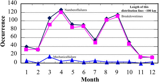
Lightning strike faults are one of the main causes of lightning arrester failure in 35 kV distribution networks. Research proposals show that in 2020, 835 insulator failures occurred in a typical distribution network in China (SL and JY, 2019), including 780 lightning breakdown failures and 55 lightning arrester failures caused by mechanical force, as shown in Figure 1.
As can be seen from Figure 1, in terms of time distribution, in 2020, there were 780 lightning breakdown faults, with a monthly average of 65, of which there were a large number in April, August, and September, followed by March, May, June, and September. This is consistent with the lightning activity in this distributed power grid. There are 55 lightning arrester failures caused by mechanical force, with an average of 5 per month. The monthly distribution of the whole year is relatively average. Mechanical force failures in lightning arresters are related to external force damage, short drainage wire caused by construction quality, stress on lightning arresters, small animals, and other factors. From this analysis, most of the faults of lightning arresters are breakdown faults.
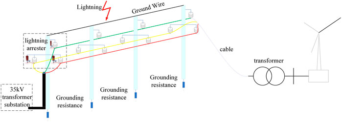
As illustrated in Figure 2, when lightning strikes the ground wire, it causes insulator flashover, and the overvoltage propagates toward the wind turbine in the form of traveling electromagnetic waves, damaging the insulation of the electrical equipment. When the insulator is connected in parallel with a metal oxide varistor (MOV) surge arrester at terminals, it can effectively suppress the occurrence of overvoltage and protect the safe and stable operation of wind farms.
Failure Mode and Effects Analysis
According to the operational data, at 23:09 on 28 February 2021, a tripping fault occurred on the observed 35 kV distribution line. Due to the heavy rains at that time, it is predicted that the line was possibly hit by a lightning strike. On the next day, it was found during inspection that the lightning arrester on phase C at the user’s side was broken, with the body of the lightning arrester disintegrated and scattered and the jumper suspended.
The distribution transformer uses a gapless zinc oxide arrester with a disconnector. The breakdown of the main body of the arrester in phase C is the cause of this trip accident. The whole arrester is broken with the conductor suspended, and consequently, the arrester at fault is disconnected from the system. Therefore, the power on the line is successfully restored. Further analysis indicated that the reason for the main body of the arrester to be broken was that the disconnector of this arrester failed to act. In addition, the jumper of the arrester in phase B was also broken during the accident. The conductor joint was bound at the lower end of the fuse, and the residual part after the action of the disconnector is still connected to the down lead of phase B.
It can be seen from this lightning strike fault that the lightning protection of 35 kV distribution lines is still the top priority for onshore wind farms, and the fragmentation of lightning arresters is mostly due to the absorption of large energies that exceed their capacity to withstand. Therefore, it is necessary to reduce the energy absorption of lightning arresters when designing novel lightning protection schemes for 35 kV distribution lines connected to onshore wind farms.
Electrical Structure of Distribution Lines
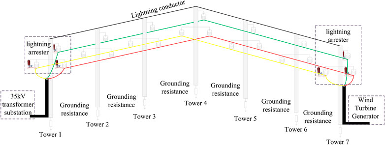
As mentioned above, the most valuable part of the onshore wind power transmission system is the distribution lines between the substation and wind turbines. The tower configurations for this section of lines are shown in Figure 3. The voltage from the wind turbine is reduced by a step-down transformer and supplied to a frequency converter. The frequency converter supplies the rectified power into the 35 kV substation through the transmission line corridor. All the towers in the corridor are fully protected by overhead ground wires. The operation mode for the wind farm is one for end-user and one for standby, and the operation mode is switched once a month. In this paper, the main power supply loop is taken as the research object. Three zinc oxide arresters are installed on the top of the head tower, and a steel bar with a diameter of 12 cm is grounded at the bottom of the tower. Three phases of the line are arranged in a mountain shape, with a span of about 60 m, and the tower has a 12 m high conical cement pole on the top. The end tower is located at the top of a 30 m high slope close to the wind turbines, equipped with three lightning arresters, and the down lead is also a stainless-steel bar with a diameter of 12 cm.
Methodology for EMTP Modeling
In order to accurately simulate the rupture accidents of lightning arresters when a 35 kV distribution line is hit by a lightning strike, the 35 kV distribution line described above is modeled by EMTP software to study the influence of lightning current amplitude on the performance of lightning arrester. Further, the improvements in the service performance of the whole system by measures to reduce the energy absorption are discussed.
Modeling of Lightning Surge Current
The lightning waveform can be described by lightning current amplitude and the lightning wave head and wave tail times (Shariatinasab et al., 2014a), which are generally described by the following formula (Eq. 1):
Where α and β are determined by the above three characteristics of lightning. The main parameters in the EMTP simulation are defined as follows: The simulation adopts the double exponential wave function to define the standard lightning current waveform 2.6/50 µs, where wave head time is set as T1 = 2.6 µs, wave head time is set as 50 µs. Accordingly, α can be calculated as 1590, whereas β is 712,000 and A is 1.1157. Im is the amplitude of lightning current signals.
Modeling of Towers and Lines in Distribution Network
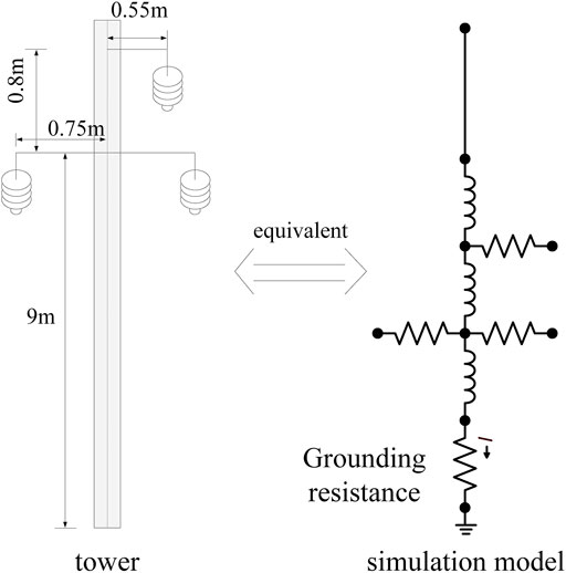
In the simulation, the tower span of 35 kV Transmission line is set as 60 m, and the lumped parameter inductance model is used to simulate the tower. The concrete pole without stay wire is selected to simulate the pole and tower, and the height of the pole and tower are set to 9 m. Details of the structures of the tower and line in the simulation are shown in Figure 4. The equivalent concentrated inductance model is adopted, and the inductance is set as 0.84 μH/m, with grounding resistance changes in the range of 5–20 Ω.
The outer diameter of the conductor is set as 11.4 mm, and the DC resistance is set as 0.4217 Ω/km. In this paper, the multi-coupler LCC subroutine of the JMarit model varying with frequency is used to build the overhead line model, and the line parameters are injected into the software to automatically generate the line module that meets the requirements of a distribution line. The main parameters of the three-phase conductor and lightning conductor of the overhead line are shown in Table 1 (Suimin and Wei, 2007).
It can be seen from Figure 3 that the height data of the relevant conductor from the ground is required when modeling the overhead conductor. According to the typical data provided in the literature [Andreottiet al., 2013], the layout position of the actual conductor on the tower is shown in Table 2.
Modeling of Insulator and Arrester
The line flashover caused by lightning is the most serious challenge for the design of line insulation. The lightning flashover rate of the distribution line needs to consider two factors, i.e., the flashover criterion of the insulator, which is determined by the lightning impulse breakdown voltage U50% of the insulator (Wang and Ren, 2020), and the calculation of induced lightning overvoltage (Andreotti et al., 2013; De Conti et al., 2010).
In the lightning protection design for the 35 kV overhead line, zinc oxide arrester is selected referred to the practical applications. Energy absorbed by lightning Arrester during lightning strikes is eventually calculated as the key parameter for the system breakdown analysis and design of the protective scheme. However, the distribution line model created in EMTP cannot be directly used to calculate the energy absorbed by a component during the entire simulation time. Therefore, the third-party module namely MODEL is used to solve this problem by using the integral calculation formula of the absorption energy of the lightning arrester. Since the EMTP software is mainly used for transient calculation, the energy absorbed was calculated at every time step. The interval for the calculation of energy absorption is decomposed and fits the time steps strictly. Eventually, all the calculated values are accumulated. The realization of this model is shown in Figure 5.
Simulation of Energy Absorbed by Lighting Arrester Under Different Lighting Overvoltage
In general, lightning would directly strike the tower or line when the hitting point is within 65 m from the line. When there are high buildings or other shielding near the distribution network, the probability of a direct lightning strike is very small. About 20% of the lightning strikes on distribution lines are direct lightning strikes, mainly in the suburbs or nearby places without high building shielding. However, about 80% of lightning events are induced lightning (Han et al., 2008). This paper mainly studies the energy absorption of line arresters under the accidents of induced lightning overvoltage of 35 kV line.
Lightning Strikes Under Different Lightning Current Amplitude
It is indicated from the simulation that induced lightning occurs near the head tower. The probability of a lightning current with amplitude greater than 88 kA is about 10%, and the probability of a lightning strike greater than 100 kA is about 7.3%. Therefore, the impact of lightning current less than 100 kA on the line is mainly considered when studying lightning protection measures (Tang et al., 2012).
When induced lightning is injected into the overhead line near tower 1 with a lightning current amplitude of 10 kA, the overvoltage waveform at different positions of the overhead line is shown in Figure 6.
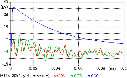
FIGURE 6. Maximum overvoltage waveform of 10 kA lightning current amplitude invading #1 overhead line near tower.
It can be seen from Figure 6 that when the amplitude of 10 kA lightning current intrudes into the overhead line, the overvoltage borne by the overhead line is small, i.e., the maximum overvoltage is only 36.5 kV, which is far from reaching the flashover voltage of the insulator. Moreover, the attenuation of the lightning intrusion wave is obvious in the propagation process. When the intrusion wave propagates to the side of the wind farm’s high-voltage cabinet, the overvoltage is very small. In consideration of the most serious cases of lightning invasion, five cases of lightning current with amplitude no less than 10 kA, i.e., 1, 30, 50, 70, and 100 kA are considered in the simulation. The simulation results are shown in Table 3.
It can be seen from Table 3 that with the increase of lightning current amplitude over 10 kA, the induced overvoltage level of overhead line is significantly enhanced, and the number of poles and towers with insulator flashover is also increasing. When the induced lightning current amplitude is between 30 and 70 kA, only tower 2 suffers from flashover. It is as predicted because the flashover of the insulator on tower 2 splits most of the lightning current through this tower. However, when the amplitude of induced lightning current reaches 100 kA, the distortion of lightning surge current only by insulator on tower 2 insulator is not enough, so the insulator on tower 2 begins to suffer from flashover.
The reason why there is no flashover for the insulator on the head tower, which is the nearest to the lightning strike location, is due to the quick response of the lightning arrester with reasonable energy absorption ability (Liao et al., 2018), and the limitation of the simulation, i.e., the judgment basis for the failure of the lightning arrester, which cannot be properly set in the software. In order to precisely study the complete process and the mechanisms of the lightning strikes on the distribution line, the energy absorbed by the lightning arrester when the lightning current amplitude reaches 100 kA should be further discussed.
The relationship between the maximum leakage current from the arrester at the pole of tower 1 and the amplitude of the lightning current is shown in Figure 7. It can be seen from Figure 7 that with the increase of lightning current amplitude, the leakage current flowing through the lightning arrester installed on tower 1 rises linearly. When the induced lightning current amplitude reaches 100 kA, the maximum leakage current of the lightning arrester can reach 19.12 kA in less than 10 µs, which could cause great damage to the lightning arrester. Therefore, it is necessary to analyze the impact of the absorbed energy on the performance and service life of the lightning arrester.
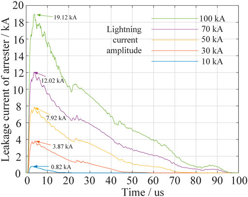
FIGURE 7. Comparison diagram of leakage current of #1 tower line arrester under different lightning current amplitudes.
Energy Absorptions in Lightning Arrester
In the case that the induced lightning occurs near tower 1, the change of energy absorbed by the arrester on tower 1 in a short time is measured with the change of lightning current amplitudes. The results of the accumulated energy were imported into MATLAB software for processing.
The changing trend of energy absorption is shown in Figure 8. It can be seen from Figure 8 that when induced lightning intrudes into overhead lines, the leakage current flowing through the arrester at tower 1 in a short time would generate huge energy in the arrester. Taking the induced lightning intrusion with the amplitude of 50 kA lightning current as an example, the energy on the arrester rises fastest within 50 µs, and the energy value reaches 90.5 kJ at 50 µs. The energy accumulated in such a short time would produce a large amount of thermal effect on the arrester, making the lightning arrester burn out.
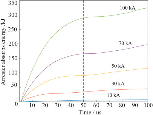
FIGURE 8. Comparison diagram of absorbed energy of #1 tower line arrester under different lightning current amplitude intrusion.
Energy Absorption Based Protective Scheme
According to the field investigations and simulation results, the terrain of the 35 kV overhead line connected to wind farms is relatively high and vulnerable to lightning strikes. Although line arresters are installed at both ends of the line, there is still a high potential for lightning trip and power failure accidents to occur, which directly affect the normal power supply of wind farms, which shows serious deficiencies in the existing lightning protection measures of this type of power supply system.
The conventional solution for the lightning protection upgrade is to replace insulators with models with better performance or simply increase the number of insulator strings, but the replacement cost is high, and increasing the number of insulator strings could lead to the increase of tower head clearance and increase the tower head size and insulation cost in consequence. Therefore, it is necessary to make a novel protective scheme to suppress dangerous lightning trips without much spending.
Retrofitting the Cross-Arm With Alternative Materials
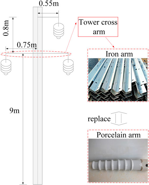
The structures of the porcelain cross-arm are shown in Figure 9. The porcelain cross arm itself is not conductive, so the insulator installed on the porcelain cross-arm is not likely to suffer from single-phase flashover when subjected to lightning strikes, and only phase-to-phase flashover with a stable power frequency arc might cause this type of cross-arm breakdown, which is much more unlikely than conventional single-phase flashover conditions (Sekioka, 2018; Sekioka, 2010; Mahmood et al., 2015).
Inspired by the outstanding performance of porcelain cross-arm, the porcelain cross-arm is tried on the distribution line, and its performance against lightning strikes is compared with the iron cross-arm. Figure 10 shows the simulation results when the lightning current amplitude is 30 kA and the induced lightning invades the overhead line, where the maximum leakage currents of the arrester at tower 1 with the cross-arm constructed in the two materials are compared.
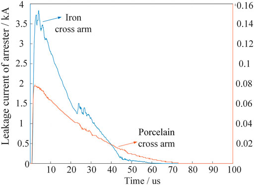
FIGURE 10. Maximum leakage current waveform of lower #1 pole arrester invaded by 30 kA lightning current amplitude of cross arms of different materials.
It can be seen from Figure 10 that the materials of the cross-arms have a great impact on the leakage current flowing through the arrester. When the lightning current amplitude is 30 kA and the induced lightning invades the overhead line, the current flowing through the arrester can be greatly reduced by using porcelain cross arms, which can be reduced by 50 times in maximum.
However, the energy absorption caused by lightning current has not changed. For the optimized implementation of the porcelain cross-arm, it is necessary to install the porcelain cross-arm on the whole line otherwise the energy still can pass through other towers. Additional protection measures need to be considered to reduce the line updating costs.
Updating Tower Grounding Body With Drag-Reduction Agent
The grounding resistance of the line is directly related to the lightning resistance level of the line (Takahashi et al., 2010). The function of the lightning arrester is that when the line is struck by lightning, the lightning arrester acts preferentially and lead the lightning current to the Earth through the grounding device, to protect the insulator and avoid flashover. According to relevant calculations, the grounding resistance of the head and end towers of the original line is about 29 Ω, so it is necessary to reduce the grounding resistance to further improve the protection ability against surge accidents.
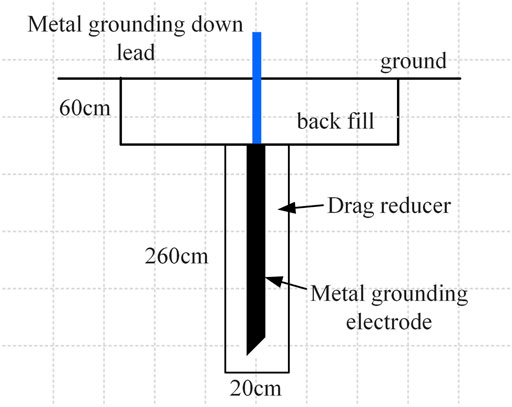
A specially designed upgradation scheme for the tower grounding body is shown in Figure 11. The grounding electrode is filled with drag-reduction agent mixed with water in the ratio of 3:2. It is noted that the grounding electrode must be fully contacted with the drag-reduction agent. After the agent is solidified, welding the galvanized steel pipes at the four corners of the underground slotted through flat steel to make them connected into the tower body. All underground connections must be welded, and the welding length shall be greater than or equal to 10 cm.
The measured grounding resistance by using this novel installation method is calculated to be within 15 Ω. Simulation on the leakage current flowing through the lightning arrester of tower 1 when the lightning current amplitude is 30 kA is carried out, under the conditions of grounding resistance with 29 and 15 Ω, respectively, as shown in Figure 12. After reducing the tower grounding resistance, when the lightning current amplitude is 30 kA and the induced lightning intrudes into the overhead line, the leakage current flowing through the arrester on tower 1 is obviously higher in the case of grounding resistance in 15 Ω, which can split more lightning energy into the ground and reduce the peak value of lightning surge current during a potential flashover. By combing the protective measures of updating cross-arm of head tower with the grounding body with reduced resistance, the effective lightning protection can be achieved for onshore wind farms without huge investments. Simulation results confirm that the lightning protection performances are almost the same for the tower body of the whole lines are updated with the agent together with only the head and end towers are equipped with porcelain cross-arms, compared with all the towers equipped with porcelain cross-arms.
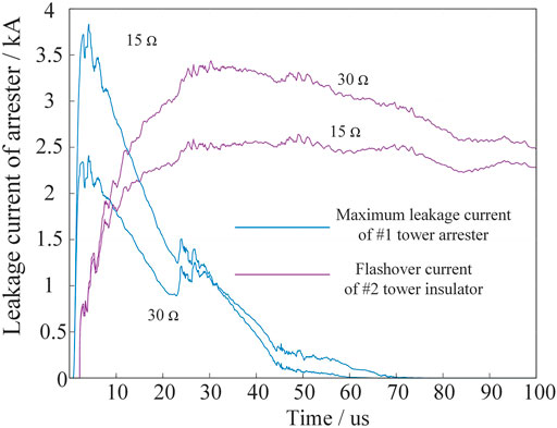
FIGURE 12. Waveform of maximum leakage current of #1 pole arrester and #2 pole insulator flashover current of different tower grounding resistance under 30 kA lightning current amplitude intrusion.
Conclusion
For the purpose of reducing the risks of frequent lightning trips of distribution line connected to onshore wind farms, a 35 kV distribution line for an onshore wind farm is selected and modelled in EMTP to study the leakage current and absorbed energy of the arrester on the head tower and the flashover of tower insulators when induced lightning surges with different lightning current amplitudes were injected into overhead lines. Further, the upgrading scheme of restraining lightning trips of the distribution line is studied. The simulation results indicate that the huge energy absorption caused by lightning surge currents within 100 μs is the main reason for the arrester to breakdown and the system to fail. Lightning trips of the 35 kV distribution line for the onshore wind farms and the breakdown of lightning arresters cannot be properly solved by conventional protective measures such as updating the insulators with better performance. Based on the principle of reducing the energy accumulated on the arrester, a novel protection scheme, in combination of refitting the head and end towers with porcelain type cross-arms and updating the grounding body of the tower with drag-reduction agents are proposed. Simulation results indicate that the lightning resistance level of the distribution can be improved by 50 times in maximum.
Data Availability Statement
The original contributions presented in the study are included in the article/Supplementary Materials, further inquiries can be directed to the corresponding author.
Author Contributions
The individual contributions of the authors are as follows: Data collection, CC; formal analysis, JG; methodology, PC; supervision, CC writing (original draft), JG. All authors have read and agreed to the published version of the manuscript.
Funding
This study received funding from research and application of key technologies for collaborative management and control of low-voltage junctions based on only fusion terminals (No. HZJTKJ2021-15).
Conflict of Interest
Author CC was employed by the company State Grid Xiongan New Area Electric Power Supply Company. Author JG was employed by the company State Grid Zhejiang Electric Power Co., Ltd., Anji County Power Supply Company. Author PC was employed by the company State Grid Xinxiang Power Supply Company.
Publisher’s Note
All claims expressed in this article are solely those of the authors and do not necessarily represent those of their affiliated organizations, or those of the publisher, the editors and the reviewers. Any product that may be evaluated in this article, or claim that may be made by its manufacturer, is not guaranteed or endorsed by the publisher.
References
Andreotti, A., Pierno, A., Rakov, V. A., and Verolino, L. (2013). Analytical Formulations for Lightning-Induced Voltage Calculations. IEEE Trans. Electromagn. Compat. 55, 109–123. doi:10.1109/TEMC.2012.2205001
Cai, L., Yu, W., Wang, J., Xu, Z., Zhou, M., and Fan, Y. (2020). Study on the thermal Behaviour and Non‐linear Coefficient of the 10 kV ZnO Surge Arrester. IET Gener. Transm. Distrib. 14, 5287–5293. doi:10.1049/iet-gtd.2020.0529
De Conti, A., Perez, E., Soto, E., Silveira, F. H., Visacro, S., and Torres, H. (2010). Calculation of Lightning-Induced Voltages on Overhead Distribution Lines Including Insulation Breakdown. IEEE Trans. Power Deliv. 25, 3078–3084. doi:10.1109/TPWRD.2010.2059050
Han, X., Mao, M., Wu, J., Zhou, W., Yu, J., Tu, J., et al. (2009). Research on Lightning Overvoltage and Comprehensive Lightning Proof Measures of 10kV Overhead Insulated Distribution Lines. High voltage Technol. doi:10.1109/APPEEC.2009.4918693
IEEE(2020). IEEE Std C62.11-2020 (Revision of IEEE Std C62.11-2012. in IEEE Standard for Metal-Oxide Surge Arresters for AC Power Circuits (>1 kV) – Redline, 1–235.
Liao, Y., Yang, J., Zhang, Y., Liu, G., Ruan, Y., and Han, Y. (2018). Effect of Equalizing Ring on Flashover Characteristics of Cat-Head Composite Insulator. in International Conference on Power System Technology (POWERCON). Guangzhou, 3455–3459. doi:10.1109/POWERCON.2018.8602014
Mahmood, F., Sabiha, N. A., and Lehtonen, M. (2015). Probabilistic Risk Assessment of MV Insulator Flashover under Combined AC and Lightning-Induced Overvoltages. IEEE Trans. Power Deliv. 30, 1880–1888. doi:10.1109/TPWRD.2015.2388634
Martinez, J. A., and Castro-Aranda, F. (2009). Lightning Performance Analysis of an Overhead Transmission Line Protected by Surge Arresters. IEEE Latin Am. Trans. 7, 62–70. doi:10.1109/TLA.2009.5173466
Nakada, K., Wakai, T., Taniguchi, H., Kawabata, T., Yokoyama, S., Yokota, T., et al. (1999). Distribution Arrester Failures Caused by Lightning Current Flowing from Customer's Structure into Distribution Lines. IEEE Trans. Power Deliv. 14, 1527–1532. doi:10.1109/61.796250
Neto, E. T. W., da Costa, E. G., and Maia, M. (2009). Artificial Neural Networks Used for ZnO Arresters Diagnosis. IEEE Trans. Power Deliv. 24, 1390–1395. doi:10.1109/TPWRD.2009.2013402
Pipelzadeh, Y., Chaudhuri, N. R., Chaudhuri, B., and Green, T. (2018). Coordinated Control of Offshore Wind Farm and Onshore HVDC Converter for Effective Power Oscillation Damping. Portland: IEEE Power & Energy Society General Meeting PESGM, 1. doi:10.1109/PESGM.2018.8586330
Sekioka, S. (2017). A Study on Multiphase Flashover in Medium Voltage Line. IEEJ Trans. PE 137, 784–790. doi:10.1541/ieejpes.137.784
Sekioka, S. (2018).Experiments for Multiphase Flashover Study in Medium-Voltage Line Due to Direct Lightning Hit. in 34th International Conference on Lightning Protection (ICLP). Moscow, 1–6. doi:10.1109/ICLP.2018.8503395
Seyyedbarzegar, S. M., and Mirzaie, M. (2016). Thermal Balance Diagram Modelling of Surge Arrester for thermal Stability Analysis Considering ZnO Varistor Degradation Effect. IET Generation, Transm. Distribution 10, 1570–1581. doi:10.1049/iet-gtd.2015.0728
Shariatinasab, R., Ajri, F., and Daman‐Khorshid, H. (2014b). Probabilistic Evaluation of Failure Risk of Transmission Line Surge Arresters Caused by Lightning Flash. IET Generation, Transm. Distribution 8, 193–202. doi:10.1049/iet-gtd.2013.0280
Shariatinasab, R., Ghayur Safar, J., and Falaghi, H. (2014a). Optimisation of Arrester Location in Risk Assessment in Distribution Network. IET Generation, Transm. Distribution 8, 151–159. doi:10.1049/iet-gtd.2013.0166
Shariatinasab, R., Gholinezhad, J., and Sheshyekani, K. (2018). Estimation of Energy Stress of Surge Arresters Considering the High-Frequency Behavior of Grounding Systems. IEEE Trans. Electromagn. Compat. 60, 917–925. doi:10.1109/TEMC.2017.2756700
Sl, D., and Jy, H. (2019). Development of a New Type of Intelligent Lightning protection Insulator for Distribution Network. Zhejiang Electric Power 38, 69–74. doi:10.19585/j.zjdl.201904012
Suimin, M., and Wei, K. (2007). Design of Overhead Transmission Lines. Beijing: China Electric Power Press.
Takahashi, A., Furukawa, S., Ishimoto, K., Asakawa, A., and Hidaka, T. (2010). Influence of Grounding Resistance on Effectiveness of Lightning protection for Power Distribution Lines with Surge Arresters. in 2010 30th International Conference on Lightning Protection (ICLP), Moscow, 1–6. doi:10.1109/ICLP.2010.7845799
Tang, J., Xu, Z., and Chen, X. (2012). Influence of High-Rise Buildings on Induced Lightning Characteristics of 35 kV Distribution Lines. Electric porcelain arrester 135, 79–84. doi:10.1016/S0378-7788(00)00125-0
Tang, Y., Zhang, Z., and Xu, Z. (2021). DRU Based Low Frequency AC Transmission Scheme for Offshore Wind Farm Integration. IEEE Trans. Sustain. Energ. 12, 1512–1524. doi:10.1109/TSTE.2021.3053051
Tsuboi, T., Takami, J., Okabe, S., Kido, T., and Maekawa, T. (2015). Energy Absorption Capacity of a 500 kV Surge Arrester for Direct and Multiple Lightning Strokes. IEEE Trans. Dielect. Electr. Insul. 22, 916–924. doi:10.1109/TDEI.2015.7076792
Wang, Z. G., and Ren, G. Q. (2020). Simulation Analysis of Lightning protection Effect and protection Range of Distribution Line Arrester Based on Atp-Emtp. Electric porcelain arrester 000, 66–70. doi:10.16188/j.isa.1003-8337.2015.01.022
Keywords: onshore wind farm, surge protection, electromagnetic transients, lightning arrester, energy absorption
Citation: Chen C, Gao J and Chu P (2022) A Novel Energy Absorption-Based Protection Scheme for Surge Transients in Large-Scale Wind Farm System. Front. Energy Res. 10:846714. doi: 10.3389/fenrg.2022.846714
Received: 31 December 2021; Accepted: 28 January 2022;
Published: 17 March 2022.
Edited by:
Jian Zhao, Shanghai University of Electric Power, ChinaReviewed by:
Huayi Wu, Hong Kong Polytechnic University, Hong Kong SAR, ChinaXi Lu, Southeast University, China
Ruixiong Li, Xi’an Jiaotong University, China
Copyright © 2022 Chen, Gao and Chu. This is an open-access article distributed under the terms of the Creative Commons Attribution License (CC BY). The use, distribution or reproduction in other forums is permitted, provided the original author(s) and the copyright owner(s) are credited and that the original publication in this journal is cited, in accordance with accepted academic practice. No use, distribution or reproduction is permitted which does not comply with these terms.
*Correspondence: Chen Chen, Y2N4YXNnQDEyNi5jb20=
 Chen Chen
 Jiuguo Gao2