 Haimeng Zhou
 Chenglong Wang
 Zhiqi Kong3
 Wei Du
95% of researchers rate our articles as excellent or good
Learn more about the work of our research integrity team to safeguard the quality of each article we publish.
Find out more
ORIGINAL RESEARCH article
Front. Energy Res. , 22 February 2022
Sec. Advanced Clean Fuel Technologies
Volume 10 - 2022 | https://doi.org/10.3389/fenrg.2022.845350
This article is part of the Research Topic Advanced Technologies in Flow Dynamics and Combustion in Propulsion and Power View all 25 articles
This article numerically studied the flow and heat transfer characteristics of the full-ribbed fluted tip of a rotor with four types of distribution of cooling films, namely, the mid-arc uniform film at the bottom of the groove, the uniform film on full perimeter ribs, the uniform film on the suction-side rib, and the uniform film on the pressure-side rib. The evolution of secondary flow in the tip clearance under these four conditions was discussed, and the effect of cooling film position on the tip leakage flow and tip heat transfer was also studied. The results showed that films in the ribs were more conducive to lower leakage flow rates and can reduce total energy losses. Adding cooling films on the single-side rib had a better effect on the control of leakage flow rate, with the most significant improvement due to adding cooling films on the suction-side rib. The mid-arc jet at the bottom of the groove can greatly contain the swirl structure in the groove, but it weakened the air sealing effect, which led to a rise in leak flow. The main reason for the swirl structure in the groove was that the leakage flow from the tip of the rotor was blocked by the cold air jet from the cooling films to form a backflow. The vortex inside the groove was the most violent when the air film hole was set on the pressure side, so the loss coefficient was higher, while the vortex inside the groove was the simplest when the cooling film hole was set on the suction side, and the energy loss caused by the vortex inside the groove was the least, and this structure was more favorable to the cooling of the leaf tip. It was also found that the uniformity of the outlet airflow angle distribution improved in the presence of cold air injection on the tip of the rotor.
In the turbine rotor of an aero-engine, the tip clearance must be reserved to prevent friction between the tip of the blade and the magazine. The working environment of the blade tip is severe. In advanced turbines, the gas with higher temperature and pressure further aggravates the operating environment of the tip. According to the research, a 1% increase in tip clearance reduces turbine stage efficiency by about 1%–2% (Bunker, 2006). Therefore, more advanced tip structures need to be applied to control the flow and heat transfer at the tip.
A great deal of research has been done on the aerodynamic and heat transfer characteristics of the rotor tips. Heyes et al. (1992) compared the flow characteristics of leaf tips with suction-side ribs and pressure-side ribs, and found that a ribbed blade tip on the suction side was significantly more effective in reducing leakage losses than a flat blade tip. Nho et al. (2012a) investigated the leakage flow of the double-notched blade tip structure and flat blade tip structure, and the results showed that the double-notched blade tip structure has less loss in all aspects than that of the flat blade tip structure. Wang et al. (2015) observed the internal flow field of a crowned blade tip by a two-dimensional cascade experiment, which verified the existence of blending losses between the leakage flow and the high-temperature mainstream of the leaf crown structure. Wheeler et al. (2011) investigated the heat transfer characteristics of the static groove blade tip clearance structure using experiments, and measured the heat transfer coefficients at different Reynolds numbers and groove width-to-height ratios, respectively, which showed that the larger the depth of the groove at the tip of the blade, the smaller the heat transfer coefficient, and whether the end wall is rotated or not has little effect on the heat transfer coefficient. Park et al. (2016) studied the heat transfer and flow characteristics of a different number of grooves in a low-speed leaf grille experiment, and the results showed that increasing the number of grooves is beneficial to reduce the total pressure loss coefficient, and the exit loss coefficient becomes smaller with the increase of the number of grooves at the top of the leaf, and adding transverse ribs is beneficial to reduce the heat transfer coefficient at the leading edge of the blade tip. Heyes et al. (1992) investigated the effect of the rib structure of the leaf tip on the leakage flow. The results showed that it is more critical to control the leakage flow than to reduce the loss in the gap. Key and Arts (2006) investigated the leakage flow at high speed in a flat and a notched blade tip structure. The results showed that slight backflow occurs inside the recess, and the recessed tip has a stronger weakening effect on the tip leakage vortex than the flat tip. Hofer and Arts (2009a) experimentally compared the aerodynamic performance of blade tip structures with different rib lengths at transonic speeds with/without cold air injection. Lee et al. (2009) measured the internal flow field and total pressure loss at different gap sizes and different rib heights within the fluted vane tip and concluded that the higher the rib height, the smaller the total loss; the closer the rib heights on both sides, the higher the efficiency; and the lower the pressure-side rib height, the smaller the increase in loss than the lower suction-side rib when the gap sizes are the same. Tallman (2004) studied the ribbed blade tips before and after the improvement by numerical simulation. Mischo et al. (2011) proposed a method to improve the notched blade tip, which can make the return strength of the notch front greatly reduced, and has a good improvement on both the loss in the gap and the heat transfer characteristics of the blade tip. Nho et al. (2012b) experimentally modified the structure of a variety of fluted blade tips and found that the addition of a triangular fluted blade tip structure on the pressure side can reduce the total pressure loss coefficient. Pouagare et al. (1986) first experimentally studied the leakage flow mechanism in the presence of cold air jets, based on a certain blade with a tip clearance of 4% chord length. The results showed that the tip jet was beneficial to weaken the tip leakage flow and improve the tip efficiency. Mercan et al. (2015) performed cold gas jetting along the mid-arc of the rotor tip of a low-pressure turbine and investigated the effect of reduced injection flow on turbine performance. Volino (2017) compared the leakage flow fields of planar and notched blade tips with different injection methods. Injecting cold air at the maximum load position of the planar blade tip can control the leakage flow better. Dey (2001) studied the effect of the leaf tip cold gas injection flow rate on the control effect of leakage flow, and the measurement results showed that the larger the cold gas injection volume, the better the control effect. Rao and Camci (2004a); Rao and Camci (2004b) investigated the leakage flow field and the vortex evolution mechanism for different cold gas flow rates as well as different jet positions when cooling air was injected into the pressure side at two gap sizes. It was shown that the jet can weaken the mixing intensity of the leaky vortex with the upper channel vortex. Hofer and Arts (2009b) investigated the effect of different Re and Ma numbers on the aerodynamic performance of the full circumferential rib tip structure and the suction-side rib tip structure with the addition of cooling gas. Du et al. (2021a); Du et al. (2021b) systematically illustrated the cooling and impact effects of air film pores in the blades. Jin et al. (2019) numerically studied the influence of different arbitrary blade tip shapes on restraining the tip leakage flow in a highly loaded turbine cascade. Kumar et al. (2020) presented the thermomechanical analysis of a typical SGT engine to study the blade tip clearance influenced by the deformation of turbine stage components (turbine rotor and nozzle guide vane (NGV) with integral blade shroud) during transient phases. Guo et al. (2019) studied the blade tip leakage vortex cavitation characteristics for an axial waterjet pump. Luo et al. (2019) numerically investigated the impact of the holes and their location on the flow and tip internal heat transfer in a U-bend channel using topological analysis. Xue and Ng (2018) provided an overview of gas turbine blade tip external cooling technologies, and they also provided an outlook on the future of cooling technology for blade tips. Choi et al. (2021) investigated the wake effects on the HTCDs from the turbine blade tip with different configurations and the corresponding shroud. Du et al. (2019) investigated the aerothermal influences of multi-cavity blade tip, and they pointed out that cavity tip reduces the blade tip heat transfer coefficient. Zhou et al. (2019) investigated the blade tip and casing heat transfer characteristics with cavity and winglet cavity tips. Zhang et al. (2014) investigated the effects of inlet turbulence and the incoming surface layer on heat transfer in leaf tip flow, and found that these two factors had almost no effect on heat transfer at the leaf tip surface. Kwak and Han (2003) studied the heat transfer characteristics of the GE-E3 turbine with cooling gas film holes on the pressure side of the plane blade tip. The results showed that the leakage flow would be blocked by the cooling gas and also weaken the heat transfer coefficient of the blade tip, and the cooling effect of the pressure-side blade tip jet cold gas was not obvious under the small blowing ratio condition. Yang et al. (2006) studied the cooling effect of different cooling air film hole arrangements on a planar leaf tip and analyzed the cooling effect of different film hole arrangement schemes. Bunker and Bailey (2001) measured the heat transfer distribution of ribbed leaf tip structures in a planar cascade and analyzed the effect of different rib heights and different oxidation levels on the heat transfer to the leaf tips. Newton et al. (2006) conducted a comparative analysis of the heat transfer and cooling characteristics of flat blade tips, suction-side ribbed blade tips, and fully ribbed blade tips, and the results showed that notched blade tips have lower leakage flow, weaker leakage vortex strength, and lower heat transfer coefficient than flat blade tips, and suction-side ribs increase the leakage flow. Kang and Lee (2016) explored the relationship among leaf tip heat transfer, rib height, and leakage flow intensity and found that the position of the separation and reattachment lines has a great influence on the bottom surface heat transfer distribution. Virdi et al. (2015) investigated the flow and heat transfer characteristics of fluted leaf tips with different clearances under the conditions of transonic motion at the end wall.
From the previous studies, it can be seen that both the ribbed tips and the cooling air injection on the blade tip are effective ways to reduce the blade tip leakage to improve the turbine efficiency and prolong the life of the turbine blades. However, the study of adding cooling air jets at different locations on the ribbed blade tip is not detailed, the flow mechanism and heat transfer characteristics of setting cooling air holes at different locations on the blade tip are not clear, and the vortex evolution process under different conditions has not been studied. Therefore, it is very necessary to study the flow and heat transfer characteristics of the blade tip after adding cooling films at four different locations, analyze the vortex structure inside and outside the notch at the top of the blade, and identify the advantages and disadvantages of each structure by comparing the effect of adding cooling films at different locations on blade tip performance.
The prototype blade used in this study is the first-stage rotor of the LISA1.5 turbine, which has high power and a low aspect ratio. There are 12 cooling films with a diameter of 0.6 mm at the rotor tip (Behr, 2007). The cooling films eject cold air vertically. The clearance of the blade tip in each case is fixed at τ = 1.2 mm. The geometrical parameters at different cross sections of the blade are shown in Table 1. Figure 1A shows the rotor blade geometry profile, and Figure 1B shows the schematic diagram of the rotor blade tip.
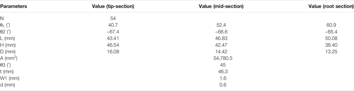
TABLE 1. Geometric parameters of different sections of the rotor.
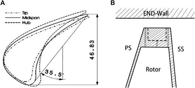
FIGURE 1. Turbine blade model (Behr, 2007). (A) The rotor profile. (B) Turbine blade model.
Figure 2 is a schematic diagram of the structure of the four types of fluted tips with cooling films used in this study. The cooling films in Case 1 are located in the middle arc at the bottom of the tip groove. In Case 2, the cooling films are distributed around the entire circumference of the tip rib. The cooling films of Case 3 are all located on the pressure side of the tip rib. The cooling films of Case 4 are all located on the suction side of the leaf tip ribs. Cooling films are evenly arranged in each structure.
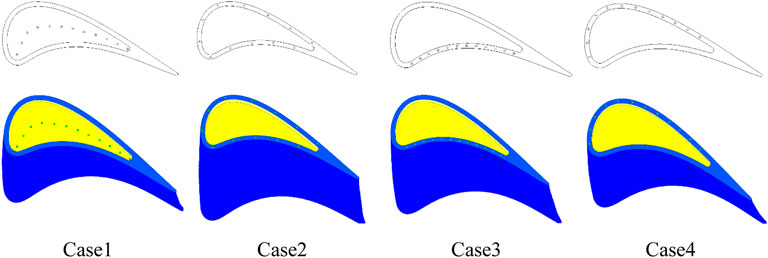
FIGURE 2. Rotor tip models with different film distributions.
The main boundary conditions for the numerical simulation are given in Table 2. Except for the inlet and outlet, all the walls are set as the adiabatic no-slip boundary. The total temperature of the inlet is 328.152 K, and the total pressure of the inlet is 328.152 K. The turbulence control is set at about 5%. The static pressure of the outlet is set to 138576 Pa. The inlet total temperature of the cooling films is 164.076 K, and the inlet total pressure of the cooling films is 145,504.8 Pa.
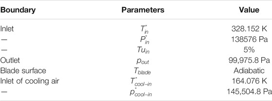
TABLE 2. LISA1.5 turbine notch blade tip boundary conditions.
The total pressure loss coefficient (Cpt) is defined by Eq. 1:
where
The static pressure coefficient (Cp) is defined as in Eq. 2:
where
The energy loss coefficient (
where
where
The heat transfer coefficient (h) is defined as in Eq. 6:
where
The adiabatic film cooling efficiency (η) is defined as (Eq. 7)
where
The LISA1.5 turbine blades were used for the numerical verification of the aerodynamic characteristics (Behr, 2007); the 3D model for the calculation is obtained by stretching the blade tips of the first-stage static blade (S1), the first-stage dynamic blade(R), and the second-stage static blade (S2). The profile data for the three rows of blades are given in Table 3, and the clearance height is set to 0.68 mm. Figure 3A shows the geometric profile of the rotor blades, and Figure 3B shows the grid schematic of the three rows of blades.
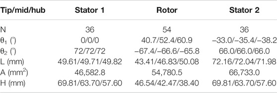
TABLE 3. Geometric feature configuration of LISA1.5 turbines.

FIGURE 3. Flat blade tips for numerical verification of aerodynamic characteristics (Behr, 2007). (A) The rotor profile. (B) Flat leaf tip grid.
ANSYS CFX is used for numerical calculations. The numerically calculated results were compared with Behr’s Behr (2007) experimental data on planar tips. Table 4 shows the boundary conditions for the numerical calculations. The wall properties of both the blade and the magazine are set to be smooth, adiabatic, and non-slip.
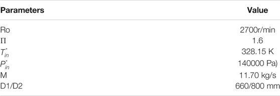
TABLE 4. LISA1.5 turbine boundary conditions for numerical verification of aerodynamic characteristics.
In this article, k-ε, k-ω, and SST turbulence models are selected to verify whether the simulation results meet the research accuracy of turbine blade tip leakage flow.
The comparison between the numerical simulation and experimental results of the total pressure coefficient (Cpt) in the radial direction of the stator outlet using different turbulence models is given in Figure 4. For the total pressure coefficient at the exit of the first-stage stator, the simulations of the three turbulence models are close to the experimental values. But for the distribution of the total pressure coefficient at the outlet of the first-stage rotor, the calculated results of all three turbulence models are smaller than the experimental values. Overall, the simulated results are slightly different from the experimental values, but the distribution trend and range of the total pressure coefficient of the SST model overlap well. It is indicated that the numerical simulation results of the selected SST turbulence model have some reliability.
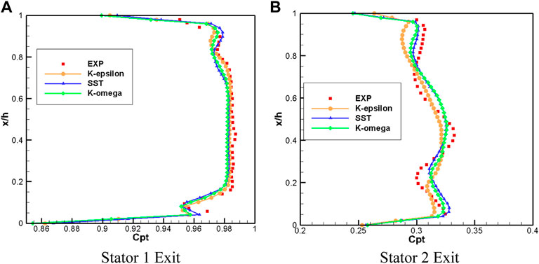
FIGURE 4. Comparison of numerical simulation results and experimental results (Behr, 2007). (A) Stator 1 Exit. (B) Stator 2 Exit.
A rotor blade tip profile of the GE-E3 turbine is stretched to obtain a 3D model for verification, which is a linear turbine cascade with film cooling. Experimental data from Kwak’s planar tip at subsonic speeds were used to verify the credibility of the numerical simulations (Kwak and Han, 2003). The geometric parameters of the computational model are shown in Table 5. The tip clearance is 1% of the blade height, the diameter of 13 films are all 1.29 mm, and they are set on the middle arc. In the experiments of Kwak et al., the positioning of the films is not given in detail. Our in-house code was used to determine the location of the films. In our in-house code, we first generate the mid-arc inside the notch at the top of the blade tip, the dimensionless position of the mid-arc near the leading edge is 0, and the dimensionless position of the mid-arc near the trailing edge is 1. The holes on the middle arc are equally distributed. Therefore, it is only necessary to give the number of air films and the dimensionless position of the first and last air films. We obtain the same experimental model as Kwak’s model by multiplying and adjusting the two dimensionless positions when the number of air film pores is fixed at 13. The distance between adjacent films is five times the film diameter. The grid field exit length is set to 2.5 times the chord length, the thickness of the first layer of the grid on the wall is 0.000001 mm, the growth ratio of the boundary layer is set to 1.2, and the y + value of the blade surface is controlled at about 1.5. The total number of grids is controlled at about 22 million. Figure 5A shows the grid of blade tip with films, and Figure 5B shows the schematic diagram of the rotor tip films.

TABLE 5. Geometric parameters of the fluted tip for verification of heat transfer characteristics.
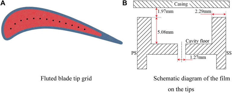
FIGURE 5. Fluted blade tips for numerical verification of heat transfer characteristics. (A) Fluted blade tip grid. (B) Schematic diagram of the film on the tips.
The boundary conditions are shown in Table 6. K-ε, SST, and k-ω turbulence models were used for the validation of blade tip heat transfer coefficients and film cooling coverage efficiency. Figure 6 shows the distribution of heat transfer coefficient (h) and film cooling efficiency (η) compared with the experimental results for the top of the blade tip ribs and the bottom of the notch for the three turbulence models, respectively. The values of heat transfer coefficients simulated by all turbulence models are higher than the experimental results, especially at the top of the ribs and near the trailing edge. The predicted results of the k-ε turbulence model differ significantly from the experimental data; the heat transfer coefficient at the position z1 of the leading edge of the blade is too high. The numerical results of the k-ω turbulence model are close to those of the SST turbulence model; the heat transfer coefficient is high at z2 and z3, respectively. Among the results predicted by the SST turbulence model, position z3 with a high heat transfer coefficient is near the middle of the blade and has the smallest range, which is closest to the experimental value. In addition, all turbulence models overestimate the film cooling efficiency near the cooling film at the bottom of the notch, especially at the leading edge of the blade. The SST turbulence model overestimates η at the suction-side edge of the blade leading edge, but the prediction is more accurate.
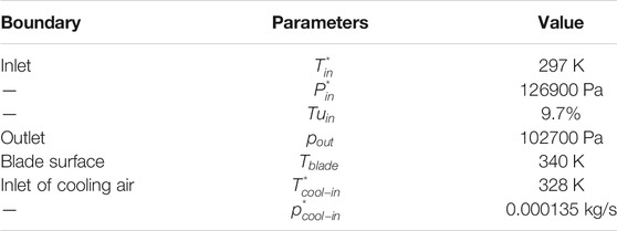
TABLE 6. Boundary conditions used to verify heat transfer characteristics.
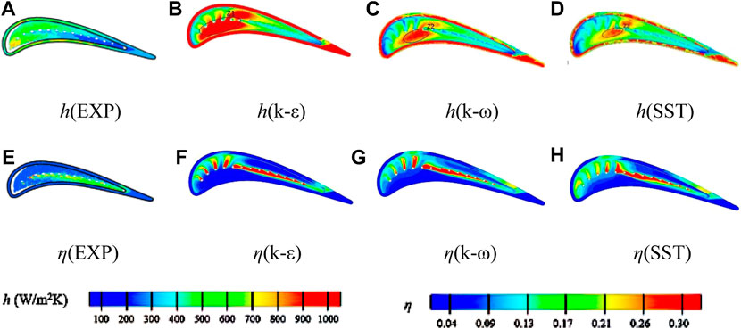
FIGURE 6. Verification of heat transfer characteristics by numerical simulation (Kwak and Han, 2003). (A) h (EXP). (B) h (k-ε). (C) h (k-ω). (D) h (SST). (E) η (EXP). (F) η (k-ε). (G) η (k-ω). (H) η (SST).
Figure 7 shows the distribution of flow stream and static pressure coefficient (Cp) in the middle section of the blade tip clearance. Figure 7E shows the distribution of flow stream and static pressure coefficient of the tip without cooling air condition, which can be used to compare with other cases. The lateral pressure gradient at the fully ribbed fluted blade tip is weakened when cooling air is injected compared to that with no cooling air. The blade tips of the four cooling film distributions all form a low-pressure zone near the suction side at greater than 25% axial position.
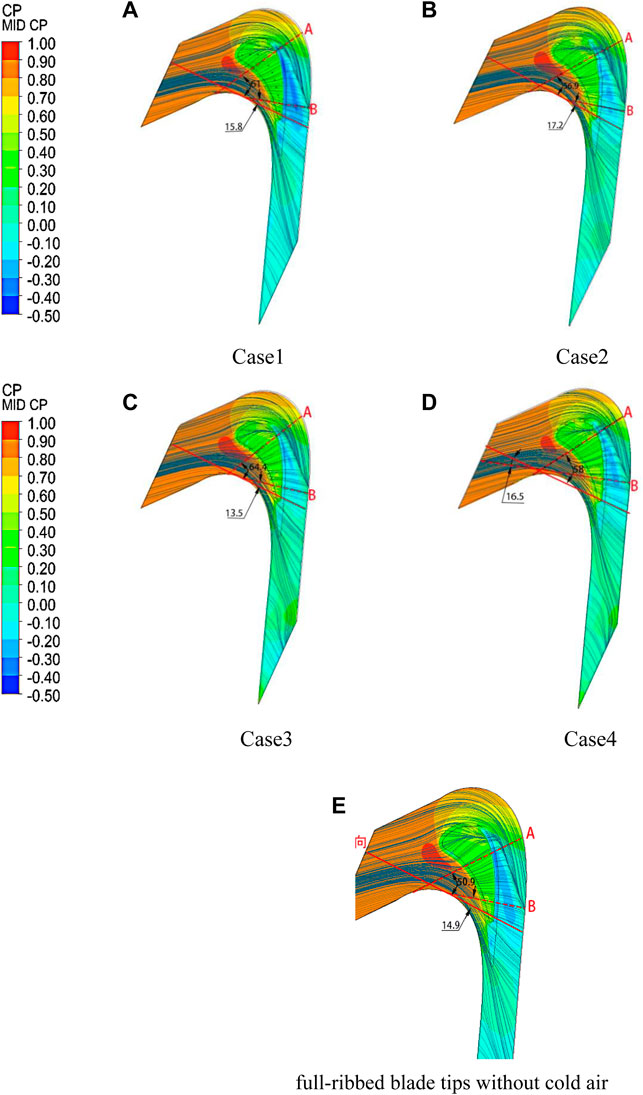
FIGURE 7. Flowlines and static pressure distribution in the interstitial section. (A) Case 1, (B) Case 2, (C) Case 3, (D) Case 4, and (E) full-ribbed blade tips without cold air.
Figure 7A shows that the blade tip with the cooling film set in the mid-arc has a larger range of low-pressure zones than the other three types of blade tips. Cooling air is injected vertically into the upper-end wall through the films and creates a small, relatively stable high-pressure zone in the interstitial channel. Influenced by the pressure distribution on the blade surface, the pressure is higher in the high-pressure area of the cooling films at the leading edge of the leaf tip, and the pressure is smaller in the high-pressure area closer to the rear.
Figure 7B shows that the airflow from the films strikes the end wall first and enters the leaf tip gap along the pressure side under the influence of the pressure difference. The pressure in the high-pressure region near the pressure-side films is higher than that near the suction-side films.
Comparing Figures 7A–D, it was found that among the four tip structures, the pressure-side ribs with added cooling films had the largest airflow folding angle (the angle of deflection of the flow line in the cascade concerning the mainstream flow line). Cooling air injection has a more pronounced impeding effect on the leakage flow of the full circumferential rib tip but not much resistance to the leakage flow of the suction-side rib tip. The position of the reattachment line (RL) and the suction-side leakage flow separation line (LSL) do not change much. Figures 7C,D show that the number of streamlines contained in the leaky flow separation line (LSL) is significantly reduced due to the sealing effect of the cooling air jets on the tip ribs on the leaky flow, which indicates that the blade tip structure with films on the ribs reduces the tip leaky flow rate, and the tip structure with films in the suction-side ribs provides better results.
Figure 7D shows that the leakage flow is accelerated twice after passing through the pressure-side ribs and is hit by the cooling airflow on the suction-side ribs at the outlet, resulting in a decrease in the leakage flow rate out of the clearance. The tip leakage flow is no longer observed in the clearance above the suction-side ribs and is replaced by a discrete strip-like leakage flow; this indicates that the ejected cooling air has suppressed most of the leakage flow in the interstitial space, and the main cause of the vortex structure in the blade tip is no longer the blade tip leakage flow but the suction leakage flow formed by the cooling air jet on the suction side.
As a result, the total energy loss at the outlet of a fluted tip structure with air film holes is higher due to the involvement of a small amount of cooling air, but the addition of air film holes can more effectively reduce the tip leakage vortex and leakage flow. The tip with films set in the suction-side ribs has the best control effect on the leakage vortex, the leak flow control effect is the worst with films set in the middle arc of the groove bottom, and the blade tip structure with films set in the pressure-side ribs is not conducive to the control of leakage vortices.
As shown in Figure 7, two radial sections “A” and “B,” which are approximately parallel to the leaf tip leakage flow, are selected to analyze the flow of leakage flow in detail. The position between cross sections “A” and “B" represents the range of the leaf tip leakage area. The solid red line is the axial direction of the blade, and the dashed line is the two cross-sectional positions of “A” and “B.”
In the four structures, the angle between section “A” and the axial direction is films set on the pressure-side rib (64.4°) > films set in the middle arc of the bottom of the notch (61.0°) > films set on the suction-side rib (58.0°) > films set on the full circumference rib (56.9°), which indicates that the leakage flow is disturbed by disturbance of the cooling air jet, the flow direction gradually changes, pressure-side rib jets have the greatest effect on flow direction, and single-side rib jets have less effect on airflow than full circumferential rib jets.
The angle between section “B” and the axial direction is films set on the full circumference rib (17.2°)> films set on the suction-side rib (16.5°)> films set in the middle arc of the bottom of the notch (15.8°)> films set on the pressure-side rib (13.5°), which indicates that the leakage fluid and high-temperature mainstream mixing angle become smaller, and then the leaf tip leakage flow direction is gradually close to the axial direction.
Figure 8 shows the total pressure loss distribution cloud of section “A,” which can reflect the flow state of the leakage flow in the complete clearance space of the leaf tip and in the straight leaf grille channel. The leakage flow near the end wall is only subject to wall friction, and the loss is small. It can be seen in section “A” that a part of the leakage flow of the four tip structures produces a vortex in the groove, but the intensity of the vortex in the groove is different.
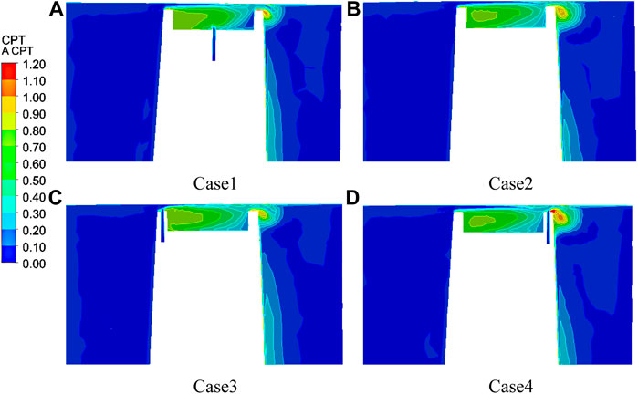
FIGURE 8. Distribution of the total pressure loss coefficient at cross-section “A” with different distributions of cooling films. (A) Case 1, (B) Case 2, (C) Case 3, and (D) Case 4.
From Figure 8A, it can be seen that when a part of the leakage flow in the recess produces a vortex, cold airflow with certain kinetic energy also joins the vortex structure in the recess in Case 1, which inevitably destroys the separation bubble at the bottom of the groove, preventing the evolution of the vortex structure and forming a low-pressure angle vortex at the intersection of the bottom of the groove and the inner wall of the suction-side ribs; it can also reduce vortex loss in the groove and the exit velocity of the leakage flow, and results in the deflection of the leakage flow on the suction side to the upper side and lower kinetic energy. The leakage vortex size is minimized, and a part of the fluid flowing out of the clearance creates a new vortex in the attachment layer of the upper magazine.
As seen in Figure 8C, the pressure-side ribs set with films have a smaller leaky vortex size and a higher leaky vortex nucleus location than the tips of the other three structures, and the airflow hitting the pressure-side ribs is initially blocked, which decelerates into the tip gap when mixed with the cold air injected from the pressure side; it further reduces the leakage flow rate into the gap and also raises the location of the incoming leakage flow upward, which forms the most developed vortex system inside the groove and enhances the mixing effect with the mainstream at the leading edge.
Figure 8D shows that the size of the leaky vortex at the tip is the largest and the position of the vortex nucleus is the lowest in Case 4. When the airflow impacted the pressure side, the leakage flow decelerated for the first time; then under the action of pressure difference, part of the leakage flow entered the groove at a faster speed to form a vortex. As the separation bubble above the ribs on the suction side is destroyed by cold air and the outlet airflow is lifted to the upper magazine by the impact of cold air, the development of the vortex inside the groove is changed and the intensity of the vortex is greatly weakened. When the vortex flows out of the suction side, the cooling air ejected from the films participates in the formation of a leaky vortex-like structure, which results in a larger leaky vortex size.
As shown in Figure 8B, the cooling air from both the pressure- and suction-side vents will affect the gap leakage flow, which causes the flow rate to slow down even more and the gap flow to lift further up the magazine.
Figure 9 shows the distribution of the total pressure loss in section “B.” It can be found that the size and loss of the leakage vortex in section “B” are higher than those in section “A.” It can be seen from Figure 9C that in Case 3, the extent and loss of the tip leakage vortex are the largest, the position of the vortex nucleus is downward, and the vortex generated by the partial leakage flow in the groove is lifted upward the largest, which forms a stronger air seal on the blade tip clearance. The leakage flow develops to downstream along the flow direction. The trailing edge of the blade width is smaller, the influence of the suction-side intrusion flow on the vortex in the trailing edge notch becomes larger, the vortex development inside the groove is hindered, and the intensity of the internal vortex is weakened to varying degrees. From Figure 9A, it can be seen that the vortex kinetic energy dissipation in the blade tip is stronger in Case 1. Figure 9D shows that a small high-pressure zone is formed above the ribs of the suction side in Case 4; the reason is that the suction-side exit velocity at the trailing edge is larger, the airflow hits the top of the ribs to form a small separation bubble, and the airflow from the suction-side ribs will destroy the separation bubble. At the same time, the cold air was ejected with a certain kinetic energy and mixed with the outlet leakage flow, which makes the suction side of the outlet air velocity greatly reduced, and airflow is lifted; therefore, the smallest leakage vortex size and the highest vortex nucleus are generated at the trailing edge in Case 4, which indicates that this blade structure is conducive to controlling the blade tip leakage flow. From the above discussion, it can be seen that under the fixed gap size, the blade tip structure with films in the bottom mid-arc of the groove and films in the suction-side ribs can effectively reduce the leakage mixing loss, among which the structure of the suction-side ribs with films provides better control of the interstitial flow at the tip.
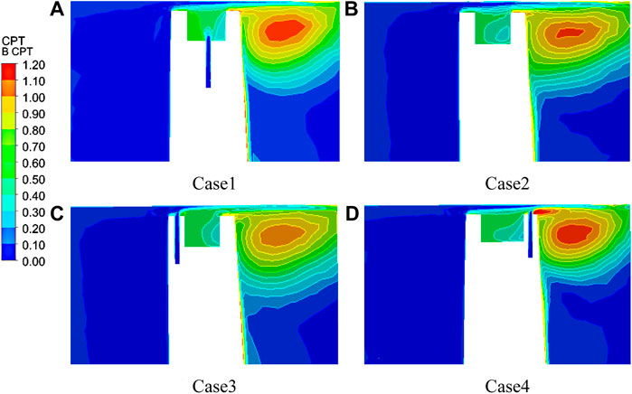
FIGURE 9. Distribution of the total pressure loss coefficient at cross-section “B” with different distributions of cooling films. (A) Case 1, (B) Case 2, (C) Case 3, and (D) Case 4.
Figure 10 shows the total outlet pressure distribution under different air film hole setting schemes. The higher the total outlet pressure, the lower the loss. The high-pressure region is the largest in Case 4, which indicates that the jet scheme has the least losses. And the high-pressure area is small in Case 2 and Case 3, which indicates that the tip loss is higher for both types of film distribution.
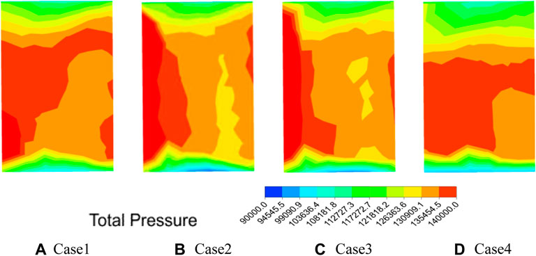
FIGURE 10. Total pressure distribution at the outlet. (A) Case 1, (B) Case 2, (C) Case 3, and (D) Case 4.
Figures 11, 12 show the distribution of the total pressure loss coefficient and the outlet airflow angle in the blade height direction, respectively. The total pressure loss coefficients of leaf roots were all close to 0.05. The total pressure loss at the tip and root is minimal (0.025) in Case 3. Two high-loss areas exist for the four different tip structures: one is the leakage vortex high-loss area of 0.97–0.99 H and the other is the channel vortex high-loss area of 0.84–0.90 H. Both high-loss areas rise along with the blade height with cooling air injection, and the high-loss area becomes smaller than a fluted blade tip without cooling films. Compared to a fluted tip without a cooling film, a fluted tip with cooling films has a reduced channel vortex loss at 0.84–0.90 H. The channel vortex loss is the smallest in Case 2. This indicates no improvement in channel eddy losses in Case 1 and Case 4. The leakage eddy loss is minimized at 0.99 H in Case 4; the high loss area of leaf tip leakage flow is the largest at the tip in Case 1. This indicates that the air film holes on the full circumferential ribs and on the suction-side ribs can significantly reduce not only the channel vortex loss but also the leakage vortex loss, while it also indicates that the air film holes on the pressure-side ribs can reduce the leakage vortex loss but increase the channel vortex loss. The four types of tip structures with cooling films have similar outlet airflow angle distribution trends along with the blade height; the uniformity of the outlet airflow angle distribution is improved with cooling films compared to the fluted tip without cooling films. The uniformity of the outlet airflow angle distribution is better in Case 1 and Case 3.
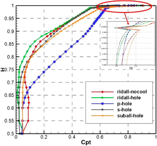
FIGURE 11. Distribution of the total pressure loss coefficient along with the blade height.
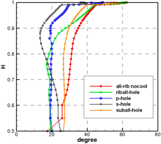
FIGURE 12. Distribution of the outlet airflow angle along with the blade height.
Figure 13 shows the distribution of streamline in cross-section “A” and cross-section “B,” which visualizes the flow of the leakage flow in the impeller and the evolution of the internal vortex system.
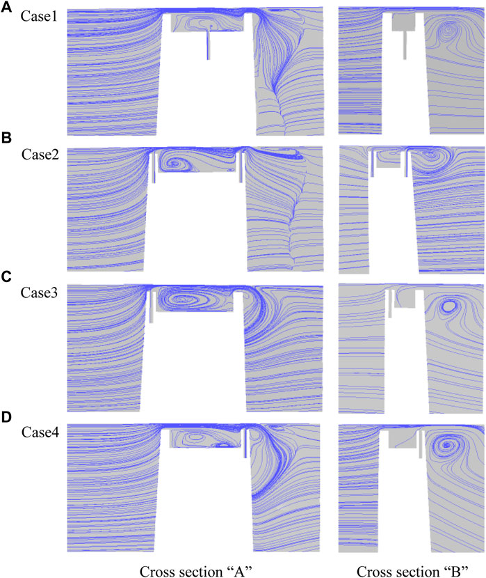
FIGURE 13. Flowline distribution of “A” and “B” cross sections of fully ribbed leaf tips with different distribution of films. (A) Case 1, (B) Case 2, (C) Case 3, and (D) Case 4.
From Figure 13A, it can be seen that the vortex structure in the recess is contained in the structure of Case 1. Although the mixing of cooling air and high-temperature leakage flow will form film protection at the bottom of the groove, the air sealing effect above the magazine is weakened, which will lead to an increase in the flow of leakage flow into the clearance.
Figures 13B–D reveal that the cooling air injected on the ribs can destroy the separation bubbles above the ribs, and most of the cooling air injected on the pressure-side ribs leaks into the upper channel vortex and evolves further, and the cooling gas injected on the suction-side ribs is influenced by the main flow of the gap exit to participate in the development of the leak-like vortex. This indicates that the air jet on the ribs is beneficial to control the leakage flow rate, especially the suction-side jet has the best effect on the pneumatic sealing of the whole blade tip. By analyzing Case 1–Case 4, the main cause of the internal vortex structure was changed from the tip leakage flow to the return flow after the cooling air jet was engaged. The leakage vortex at the suction side of section “B” is larger than that of section “A” and farther from the suction surface. The gap leakage flow in cross-section “A” is first dissipated by the kinetic energy of a part of the pressure-side rib jet and then disturbed by the return flow of the jet plug on the suction side, creating a medium-sized angular vortex near the pressure side of the groove and a small angular vortex near the suction side of the groove in Case 2. The vortex inside the groove is the least developed in Case 4, which means that the vortex loss in the recess is minimized, and the bottom separation bubble in the recess near the suction side is increased by the influence of the cold air on the suction side, which is more conducive to blade cooling.
As shown in Figure 14, for different blade tip clearance under the blade, suction surface and pressure surface limit the flow line distribution. From the left suction-side surface flow line distribution, it can be seen that the leaf tip secondary flow covers nearly a quarter of the channel height near the trailing edge of the blade. The position above the yellow dashed line indicates the area of small vortices caused by the interstitial flow perpendicular to the leaf tip. The red dashed line in the figure shows the reattachment line of the tip leakage vortex (TLV) and the tip channel vortex (TPV), and the green dashed line indicates the separation line of the tip passage vortex (TPV).
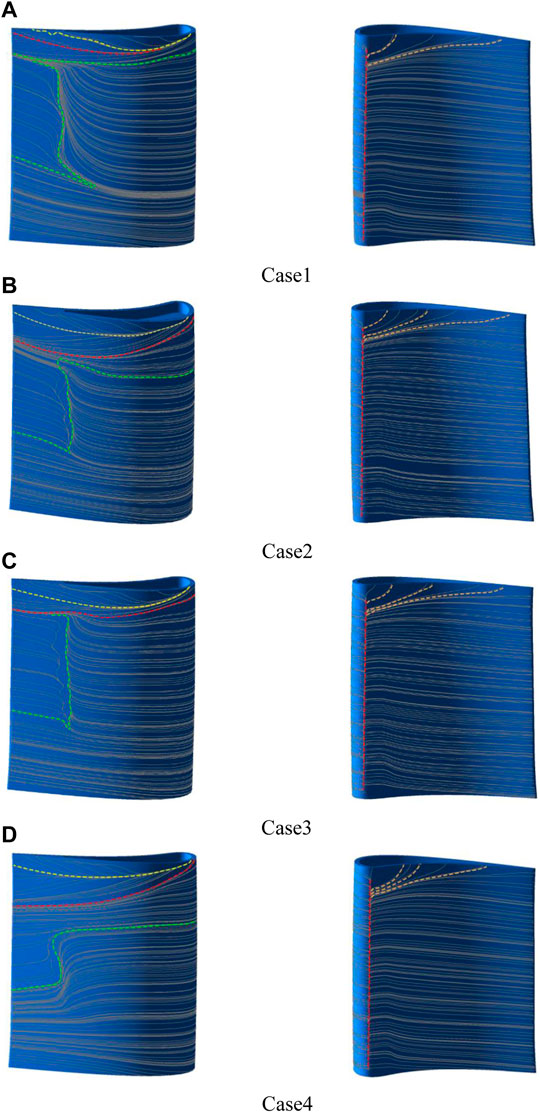
FIGURE 14. Streamline distribution of blade surface. (A) Case 1, (B) Case 2, (C) Case 3, and (D) Case 4.
As shown in Figure 14A, in Case 1, the extent of the separation bubble at the tip of the leaf closest to the suction side is the smallest, and the position of the separation bubble moves up along the flow direction and disappears at the trailing edge. The small vortex region at the tip gradually becomes larger, and the vortex region is lifted upward at the trailing edge. Only in Case 1, the reattachment lines of the tip leakage vortex (TLV) and tip passage vortex (TPV) are shifted upward along the flow direction, and the reattachment lines of the rest of the cases are shifted downward along the flow direction.
As shown in Figure 14C, in Case 3, the vortex range in the suction surface is minimal and disappears at the trailing edge of the ribs. The radial extent of the vortex caused by the airflow perpendicular to the gap at the tip of the leaf is minimal. It may be due to the fact that the cold air has some kinetic energy in Case 3, which increases the blocking effect of the clearance entrance.
As shown in Figures 14B,D, the range of reattachment line at the tip is wider in Case 2 and Case 4, which suggests that both types of leaf tips can develop a more complete leakage vortex on the suction side, and the flow is more developed downstream, causing the reattachment line to move downstream along the flow direction. The shape of the reattachment line is more moderate in Case 2. The channel vortex separation line is the closest to the top, and the reduction in channel vortex loss is the greatest in Case 4; its channel vortex range is also smaller, and the channel vortex (TPV) separation line near the trailing edge is tilted upward to a greater extent, which indicates that the suction side of the rib tip is conducive to weakening the channel vortex. However, the channel vorticity line of the blade tip with film holes on the full circumference rib and the pressure-side rib is gently inclined upward near the trailing edge, which implies that the channel vortices of these two types of tips are more developed along the flow direction, and the channel vortices of the tips with films on the pressure-side ribs are the most strongly mixed with the leakage vortices.
The surface flow line on the pressure side shows that after the airflow strikes the end wall, part of the fluid passes laterally through the cascade channel, and the red separation line on the pressure side all moves to the front edge, the moving distances are Case 4, Case 1, Case 3, and Case 2 in the descending order; the greater the distance the separation line moves forward, the more favorable the tip structure is to improve the angle of attack of the incoming flow.
From the previous discussion, it is clear that the structure of the fluted leaf tip with cold air affects the flow of the leakage stream as well as the development and evolution of the leakage vortex. The variation of leakage vortex and channel vortex losses caused by different cooling film distributions are also different.
Table 7 shows the total energy loss and relative leakage flow of the cascade for different tip configurations, which can more visually compare the impact of different cooling film arrangements on aerodynamic performance. As shown in Table 7, the total loss of the fully ribbed fluted tip structure with the addition of cooling air injection is higher than that without cooling air, but the increase in total loss due to cold air is not significant because the proportion of the cooling airflow to the total flow is small. Case 1 has the lowest total pressure loss at the leaf tip, about 0.122515; Case 2 has the highest leaf tip loss, about 0.139805; and Case 4 has lower leaf tip loss than Case 3. The fully ribbed fluted tip structure with cooling air injection has a lower leakage flow than that without cooling air; Case 1 has the highest leakage flow rate of about 0.007788 kg/s; and the leakage flow rate of Case 4 is the smallest, about 0.006685 kg/s.
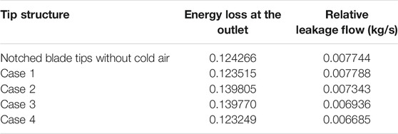
TABLE 7. Exit aerodynamic parameters of the blade tip with different cooling film distributions.
In summary, the addition of film holes on the ribs is more conducive to reducing the leakage flow rate. In particular, when the number of air film holes is fixed, adding films on the single-side rib has a better control effect on leakage flow, and adding films on the suction-side rib has the most significant improvement effect. Adding films on the arc at the bottom of the groove is beneficial to reduce the energy loss of the blade, but it will increase the relative leakage flow rate. Adding the films to the suction-side rib will not only reduce the total energy loss but also reduce the leakage flow rate.
Figure 15 shows the distribution of film cooling efficiency η at the top of the rib and the bottom of the groove under the four cooling film hole arrangements. While the low-temperature air released from the interior of the blade participates in the evolution of the vortex structure, it also changes the distribution of the tip surface temperature. The films in Case 1 have the largest coverage of the groove, and the film coverage of the tip ribs is very low.
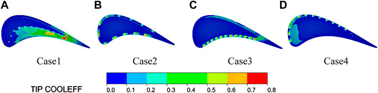
FIGURE 15. Film cooling efficiency for different air film hole distribution schemes η. (A) Case 1, (B) Case 2, (C) Case 3, and (D) Case 4.
The overall cooling efficiency of the blade tip structure with films added to the ribs is similar and low. In Case 3, the cooling air not only achieves high-intensity cooling on the pressure-side ribs but also can appropriately suppress the heat load of the suction-side ribs. In Case 4, the cooling air not only achieves high-intensity cooling on the suction-side ribs, and in the leading edge of the blade notch position, the cold air has a covering effect. After the tip clearance flow is decelerated by the cooling air from the pressure-side ribs at the entrance of the clearance, most of the cooling air mixed with the leakage flow participates in the development of the vortex in the groove cavity, and a small part of the fluid passes through the blade tip to cool the suction-side ribs. In Case 2, the cooling air jet achieves a more comprehensive discretization cooling of the ribs.
In this article, the flow and heat transfer characteristics of the fluted blade tip of a rotor were studied under different configurations of cooling films. The effect of the cooling film position on the tip leakage flow and the aerodynamic characteristics of the tip was analyzed. The vortex structure inside the blade tip recess and the development of secondary flow in the clearance were compared for four types of the air film aperture distribution. The main conclusions obtained are as follows:
1) The total loss of the full-ribbed fluted tip structure with the addition of cooling air injection is higher than that without cooling air; however, the proportion of cold airflow to total flow was small, so the increase in total loss due to cooling air is not significant. The total pressure loss for the tip with cooling films added to the arc in the groove is the smallest, the value is approximately 0.122515, the tip with uniform films on full perimeter ribs has the highest loss, and the value of the loss is about 0.139805.
2) The addition of cooling air injection on the ribs was more conducive to reducing the leakage flow rate, the most significant improvement was achieved by adding cooling films to the suction-side ribs, and the leakage flow rate of the tip was about 0.006685 kg/s. The highest leakage flow rate was found for the tip with the cooling film added to the arc in the groove, with a value of 0.007788 kg/s. The swirl structure inside the groove was mainly caused by the return flow of the tip leakage stream from the cooling air jet. The vortex in the groove evolved most intensely when the films on the pressure-side ribs eject cooling air.
3) The uniformity of the outlet flow angle distribution was improved when there was cold air injection. Adding cooling films in the middle arc of the bottom of the groove and on the pressure-side ribs can improve the uniformity of the outlet flow angle distribution better than other structures.
4) The cooling air can effectively cover the groove by adding films in the middle arc of the tip groove. The cooling air can effectively cover the rib when adding cooling films to the ribs, but inside the recess, the cooling air barely covers the bottom.
The original contributions presented in the study are included in the article/Supplementary Material, further inquiries can be directed to the corresponding author.
All authors listed have made a substantial, direct, and intellectual contribution to the work and approved it for publication.
The authors declare that the research was conducted in the absence of any commercial or financial relationships that could be construed as a potential conflict of interest.
All claims expressed in this article are solely those of the authors and do not necessarily represent those of their affiliated organizations, or those of the publisher, the editors, and the reviewers. Any product that may be evaluated in this article, or claim that may be made by its manufacturer, is not guaranteed or endorsed by the publisher.
The authors would like to acknowledge the support of the National Natural Science Foundation of China (Number 52076053) and the National Natural Science Foundation of China (Youth Foundation) (Number 12002374).
Behr, T. (2007). Control of Rotor Tip Leakage and Secondary Flow by Casing Air Injection in Unshrouded Axial Turbines. Dresden: Dresden University of Technology. doi:10.3929/ethz-a-005478482
Bunker, R. S., and Bailey, J. C. (2001). “Effect of Squealer Cavity Depth and Oxidation on Turbine Blade Tip Heat Transfer,” ASME Article No, GT2000-0155 in ASME Turbo Expo 2000, New Orleans, LA, June, 2001. doi:10.1115/2001-GT-0155
Bunker, R. S. (2006). Axial Turbine Blade Tips: Function, Design, and Durability. J. Propul. Power 22, 271–285. doi:10.2514/1.11818
Choi, S. M., Bang, M., Moon, H. K., and Cho, H. H. (2021). Wake Effects on Heat Transfer from a Turbine Blade Tip with Different Configurations and its Corresponding Shroud. Int. Commun. Heat Mass Transfer 126, 105333. doi:10.1016/j.icheatmasstransfer.2021.105333
Dey, D. (2001). Aerodynamic Tip Desensitization in Axial Flow Turbines. State College: Pennsylvania State University.
Du, K., Li, Z., Li, J., and Sunden, B. (2019). Influences of a Multi-Cavity Tip on the Blade Tip and the over Tip Casing Aerothermal Performance in a High Pressure Turbine cascade. Appl. Therm. Eng. 147, 347–360. doi:10.1016/j.applthermaleng.2018.10.093
Du, W., Luo, L., Wang, S., and Sunden, B. (2021). Film Cooling in the Trailing Edge Cutback with Different Land Shapes and Blowing Ratios. Int. Commun. Heat Mass Transfer 125, 105311. doi:10.1016/j.icheatmasstransfer.2021.105311
Du, W., Luo, L., Jiao, Y., Wang, S., Li, X., and Sunden, B. (2021). Heat Transfer in the Trailing Region of Gas Turbines - A State-Of-The-Art Review. Appl. Therm. Eng. 199, 117614. doi:10.1016/j.applthermaleng.2021.117614
Guo, Q., Huang, X., and Qiu, B. (2019). Numerical Investigation of the Blade Tip Leakage Vortex Cavitation in a Waterjet Pump. Ocean Eng. 187, 106170. doi:10.1016/j.oceaneng.2019.106170
Heyes, F. J. G., Hodson, H. P., and Dailey, G. M. (1992). The Effect of Blade Tip Geometry on the Tip Leakage Flow in Axial Turbine Cascades. J. Turbomach. 114, 643–651. doi:10.1115/1.2929188
Hofer, T. s., and Arts, T. (2009a). “Aerodynamic Investigation of the Tip Leakage Flow for Blades with Different Tip Squealer Geometries at Transonic Conditions,” in ASME Turbo Expo 2009: Power for Land, Sea, and Air, Orlando, FL, June, 2009 (American: American Society of Mechanical Engineers (ASME)), 1051–1061. doi:10.1115/GT2009-59909
Hofer, T. s., and Arts, T. (2009b). “Aerodynamic Investigation of the Tip Leakage Flow for Blades with Different Tip Squealer Geometries at Transonic Conditions,” ASME Article No. GT2009-59909 in ASME Turbo Expo 2009, Orlando, FL, June, 2009. doi:10.1115/GT2009-59909
Jin, J., Song, Y., Yu, J., and Chen, F. (2019). Modification and Optimization Strategies for Turbine Arbitrary Blade Tips. Proc. Inst. Mech. Eng. A: J. Power Energ. 233, 675–688. doi:10.1177/0957650919826326
Kang, D. B., and Lee, S. W. (2016). Effects of Squealer Rim Height on Heat/mass Transfer on the Floor of Cavity Squealer Tip in a High Turning Turbine Blade cascade. Int. J. Heat Mass Transfer 99, 283–292. doi:10.1016/j.ijheatmasstransfer.2016.03.121
Key, N. L., and Arts, T. (2006). Comparison of Turbine Tip Leakage Flow for Flat Tip and Squealer Tip Geometries at High-Speed Conditions. J. Turbomach. 128, 213–220. doi:10.1115/1.2162183
Kumar, R., Kumar, V. S., Butt, M. M., Sheikh, N. A., Khan, S. A., and Afzal, A. (2020). Thermo-mechanical Analysis and Estimation of Turbine Blade Tip Clearance of a Small Gas Turbine Engine under Transient Operating Conditions. Appl. Therm. Eng. 179, 115700. doi:10.1016/j.applthermaleng.2020.115700
Kwak, J. S., and Han, J.-C. (2003). Heat Transfer Coefficients and Film Cooling Effectiveness on the Squealer Tip of a Gas Turbine Blade. J. Turbomach. 125, 648–657. doi:10.1115/1.1622712
Lee, S. W., Moon, H. S., and Lee, S. E. (2009). Tip Gap Height Effects on Flow Structure and Heat/Mass Transfer over Plane Tip of a High-Turning Turbine Rotor Blade. Int. J. Heat Fluid Flow 30, 198–210. doi:10.1016/j.ijheatfluidflow.2008.12.009
Luo, L., Zhao, Z., and Kan, X. (2019). On the Heat Transfer and Flow Structures’ Characteristics of the Turbine Blade Tip Underside with Dirt Purge Holes at Different Locations by Using Topological Analysis. J. Turbomach. 141, 071004. doi:10.1115/1.4042654
Mercan, B., Doğan, E., Ostovan, Y., and Uzol, O. (2015). Effects of Camberwise Varying Tip Injection on Loss and Wake Characteristics of a Low Pressure Turbine Blade. Int. J. Heat Fluid Flow 54, 119–130. doi:10.1016/j.ijheatfluidflow.2015.04.008
Mischo, B., Burdet, A., and Abhari, R. S. (2011). Influence of Stator-Rotor Interaction on the Aerothermal Performance of Recess Blade Tips. J. Turbomach. 133, 011023. doi:10.1115/1.4001134
Newton, P. J., Lock, G. D., Krishnababu, S. K., Hodson, H. P., Dawes, W. N., Hannis, J., et al. (2006). Heat Transfer and Aerodynamics of Turbine Blade Tips in a Linear cascade. J. Turbomach. 128, 300–309. doi:10.1115/1.2137745
Nho, Y. C., Park, J. S., Lee, Y. J., and Kwak, J. S. (2012). Effects of Turbine Blade Tip Shape on Total Pressure Loss and Secondary Flow of a Linear Turbine cascade. Int. J. Heat Fluid Flow 33, 92–100. doi:10.1016/j.ijheatfluidflow.2011.12.002
Nho, Y. C., Park, J. S., Lee, Y. J., and Kwak, J. S. (2012). Effects of Turbine Blade Tip Shape on Total Pressure Loss and Secondary Flow of a Linear Turbine Cascade. Int. J. Heat Fluid Flow 33, 92–100. doi:10.1016/j.ijheatfluidflow.2011.12.002
Park, J. S., Lee, S. H., Lee, W. S., Chung, J. T., and Kwak, J. S. (2016). Heat Transfer and Secondary Flow with a Multicavity Gas Turbine Blade Tip. J. Thermophys. Heat Transfer 30, 120–129. doi:10.2514/1.T4541
Pouagare, M., Weinhold, W., and Weinhold, W. (1986). “Tip Leakage Reduction through Tip Injection in Turbomachines,” AIAA-86-1764 in 22nd Joint Propulsion Conference, Huntsville, Alabama, June, 1986. doi:10.2514/6.1986-1746
Rao, N. M., and Camci, C. (2004). “Axial Turbine Tip Desensitization by Injection from a Tip Trench: Part 1 - Effect of Injection Mass Flow Rate,” in ASME Turbo Expo 2004: Power for Land, Sea, and Air, Vienna, Austria, June, 2004 (American Society of Mechanical Engineers (ASME)), 1075–1088. doi:10.1115/GT2004-53256
Rao, N. M., and Camci, C. (2004). “Axial Turbine Tip Desensitization by Injection from a Tip Trench: Part 2 - Leakage Flow Sensitivity to Injection Location,” in ASME Turbo Expo 2004: Power for Land, Sea, and Air, Vienna, Austria, June, 2004 (American Society of Mechanical Engineers (ASME)), 1089–1098. doi:10.1115/GT2004-53258
Tallman, J. A. (2004). A Computational Study of Tip Desensitization in Axial Flow Turbines Part2: Turbine Rotor Simulations with Modified Tip Shapes. ASME Article No. GT2004-53919. doi:10.1115/gt2004-53919
Virdi, A. S., Zhang, Q., He, L., Li, H. D., and Hunsley, R. (2015). Aerothermal Performance of Shroudless Turbine Blade Tips with Relative Casing Movement Effects. J. Propul. Power 31, 527–536. doi:10.2514/1.B35331
Volino, R. J. (2017). Control of Tip Leakage in a High-Pressure Turbine cascade Using Tip Blowing. J. Turbomach. 139, 061008. doi:10.1115/1.4035509
Wang, J., Sundén, B., Zeng, M., and Wang, Q. (2015). Film Cooling Effects on the Tip Flow Characteristics of a Gas Turbine Blade. Propul. Power Res. 4, 9–22. doi:10.1016/j.jppr.2015.02.003
Wheeler, A. P. S., Atkins, N. R., and He, L. (2011). Turbine Blade Tip Heat Transfer in Low Speed and High Speed Flows. J. Turbomach. 133, 41–55. doi:10.1115/1.4002424
Xue, S., and Ng, W. (2018). Turbine Blade Tip External Cooling Technologies. Aerospace 5, 90. doi:10.3390/aerospace5030090
Yang, H., Chen, H.-C., and Han, J.-C. (2006). Film-Cooling Prediction on Turbine Blade Tip with Various Film Hole Configurations. J. Thermophys. Heat Transfer 20, 558–568. doi:10.2514/1.18422
Zhang, Q., He, L., and Rawlinson, A. (2014). Effects of Inlet Turbulence and End-wall Boundary Layer on Aerothermal Performance of a Transonic Turbine Blade Tip. J. Eng. Gas Turb Power 136, 052603. doi:10.1115/1.4026002
Zhou, Z., Chen, S., Li, W., and Wang, S. (2019). Thermal Performance of Blade Tip and Casing Coolant Injection on a Turbine Blade with Cavity and Winglet-Cavity Tip. Int. J. Heat Mass Transfer 130, 585–602. doi:10.1016/j.ijheatmasstransfer.2018.10.130
τ Tip clearance height
n Number of turbine blades
Ro Rotation speed
θ1 Inlet geometric angle
θ2 Outlet geometric angle
L Axial chord length
H Blade height
D Throat diameter
A Throat area
θ3 Inlet angle
t Pitch
W1 Groove width
h Groove depth
d Film diameter
π Pressure ratio
m Mass Flow
D1 Hub diameter
D2 Tip diameter
W2 Rib width
η Cooling efficiency of film
Cp Static pressure coefficient
RL Reattach line
LSL Leakage flow separation line
TLV Tip leakage vortex
TPV Tip passage vortex
Keywords: fluted blade tip, blade tip leakage flow, film cooling, rotor, heat transfer
Citation: Zhou H, Wang C, Kong Z, Du W and Wang Z (2022) Effect of Film Position on the Flow and Heat Transfer Characteristics of Full-Ribbed Rotor Tip. Front. Energy Res. 10:845350. doi: 10.3389/fenrg.2022.845350
Received: 29 December 2021; Accepted: 17 January 2022;
Published: 22 February 2022.
Edited by:
Xiao Liu, Harbin Engineering University, ChinaReviewed by:
Jie Gao, Harbin Engineering University, ChinaCopyright © 2022 Zhou, Wang, Kong, Du and Wang. This is an open-access article distributed under the terms of the Creative Commons Attribution License (CC BY). The use, distribution or reproduction in other forums is permitted, provided the original author(s) and the copyright owner(s) are credited and that the original publication in this journal is cited, in accordance with accepted academic practice. No use, distribution or reproduction is permitted which does not comply with these terms.
*Correspondence: Chenglong Wang, d2FuZ2NoZW5nbG9uZ2dma2RAMTYzLmNvbQ==
Disclaimer: All claims expressed in this article are solely those of the authors and do not necessarily represent those of their affiliated organizations, or those of the publisher, the editors and the reviewers. Any product that may be evaluated in this article or claim that may be made by its manufacturer is not guaranteed or endorsed by the publisher.
Research integrity at Frontiers
Learn more about the work of our research integrity team to safeguard the quality of each article we publish.