 Xingfeng Xie
 Zaijun Wu1*
 Qinran Hu
94% of researchers rate our articles as excellent or good
Learn more about the work of our research integrity team to safeguard the quality of each article we publish.
Find out more
ORIGINAL RESEARCH article
Front. Energy Res. , 13 April 2022
Sec. Smart Grids
Volume 10 - 2022 | https://doi.org/10.3389/fenrg.2022.844713
This article is part of the Research Topic Intelligent Operation and Control in Next Generation Urban Power Grid View all 14 articles
Modular multilevel converters (MMCs), as one of the core components of hybrid AC/DC power grids, become the preferred converter topology and show good developments. Urgently, a general MMC modeling scheme with good model accuracy needs to be developed to realize small-signal analyses and designs for the large-scale AC/DC power grids easily. This paper proposes a unified modeling scheme (UMS) for MMC systems in a synchronous rotating (dq) reference frame. Based on the dynamic phasor theory and with the proposed modular decouple modeling (MDM), the nonlinear state-space model of the overall MMC system can be obtained by configuring and connecting the input and output of the state-space model of each subsystem. Besides, the unified controller, modeling different control modes, normalizes the MMC systems modeling. Simultaneously, with the proposal of UMS, linearization and splicing could be uesd to develop a small-signal model of the overall MMC system directly. Therefore, the proposed model is suitable for simulating the large-scale hybrid AC/DC power grids and analyzing the stability of small-signal. Finally, the simulation results verify the accuracy and effectiveness of the proposed modeling method.
A large number of distributed energy resources (DERs), from transmission systems to distribution networks, have been integrated into power grids to realize low-carbon energy systems. Flexible hybrid AC/DC power grids can effectively serve the grid connection and consumption of large-scale renewable energy. In particular, high-voltage direct current (HVDC) transmission technology has good application prospects in the field of renewable consumption and long-distance transmission (Liu et al., 2014; Zhu et al., 2021; Zhao and Tao, 2021); In addition, with the development of urbanization and the rapid growth of DC load, DC distribution network has attracted extensive attentions from scholars and the industry because of its flexible control (Sun et al., 2021; Xianyong et al., 2021). Modular multilevel converters (MMCs) become the preferred topology of high power converters for flexible AC/DC power grids, showing good development prospects (Trinh et al., 2016; Wang et al., 2021). Therefore, a model reflecting the general operating rules of MMC systems can provide essential guidance in studying the operation characteristics of hybrid AC/DC power grids, selecting the operational parameters of circuits, designing the controllers, and analyzing the stability of AC/DC power grids.
The internal dynamic of MMC is very complex (Harnefors et al., 2013) due to circulating currents and internal capacitor voltages, which results in the harmonic components in the arms (Ilves et al., 2012). Therefore, compared to traditional two-level VSC systems, MMC is more challenging to model and control.
As to the MMC modeling in large-scale hybrid AC/DC power grids, the computational burden introduced by the detailed electromagnetic transient (EMT) highlights the need to develop simplified models that provide similar behaviors and dynamic responses. Because the average arm model (AAM) significantly reduces complexity while maintaining a satisfactory representation of internal dynamics (Antonopoulos et al., 2009), the average model represented by AAM is suitable for simplified simulations and analyses, and has been widely used in the design of control systems (Harnefors et al., 2013; Saad et al., 2015).
Based on the AAM approach in three-phase stationary (ABC) reference frame, Gnanarathna et al. (2011) proposed a time-varying model of MMC and Peralta et al. (2012) put forward a detailed and averaged MMC model to improve simulation speed. Although these models can improve simulation speed in large-scale system simulation. However, they are not suitable for eigenvalue analyses due to the time-variance.
Motivated by the need for studies in eigenvalue-based small-signal stability of MMC-based power grids, the modeling in the dq reference frame has been widely used for modeling MMC systems. In addition, the design of MMC’s control system is usually implemented in the dq frame, making the development of the overall MMC model and its interfacing much easier. Munch et al. (2009) presented a state-space description in the dq frame for the optimal design of the controller. Vatani et al. (2015) put forward other simplified fundamental frequency models of MMC. In order to facilitate the analysis of large-scale AC/DC power systems. Trinh et al. (2016) and Li et al. (2018) developed the simplified and reduced-order MMC models. But these models are only fit for the fundamental frequency, ignoring the high harmonic parts of the internal dynamics of the converter, such as harmonic circulating currents.
The dynamic-phasor-based modeling, which is based on the generalized average method (Sanders et al., 1990), can replace traditional modeling with time-domain (differential) equations, because the dynamic-phasor modeling is inherent time-invariance and greatly reduces the simulation time without losing accuracy. Deore et al. (2012) first applied the dynamic phasor modeling method in the MMC-HVDC system, where a state-space model with 98 states was developed. However, the model is highly complex, including many complex dynamic equations. Jamshidifar and Jovcic (2016) proposed a dynamic state-space model of MMC for analyzing small-signal dynamics and designing controllers, but control system modeling is not covered in the model. Jovcic and Jamshidifar (2015) built an average-model-based dynamic phasor model of MMC, whose electrical system and control system are coupled together, leading to the inconvenience of connecting the MMC model with both external control and DC electrical parts.
As seen from the previous analyses, the models in the ABC frame are applicable to the trial-and-error study of time-domain simulation, but these models are not suitable for the study of the eigenvalue-based small-signal stability in MMC-based power grids. Although many efforts have been made on MMC modeling in the dq frame, a general MMC modeling scheme with high model accuracy urgently needs to develop to realize small-signal analyses and designs for the large-scale AC/DC power grids easily.
This paper proposes a unified modeling scheme (UMS) for MMC systems in a synchronous (dq) reference frame for the analyses of both MMC-based system operation and small-signal stability. The modular decouple modeling (MDM) and the unified controller modeling make MMC systems modeling more flexible and expansible to adapt to different hybrid AC/DC power grids. Besides, based on the proposed model, the small-signal model of the overall MMC system could be developed directly by linearizing and then splicing our model, which can avoid the direct derivation of the overall system matrix element. Therefore, our model is suitable for simulating the large-scale hybrid AC/DC power grids as well as studying small-signal stability. The accuracy and effectiveness of the proposed modeling method are verified by a simulation test system in MATLAB/Simulink.
A three-phase model of MMC is shown in Figure 1. The MMC is assumed to be connected to an infinite power supply through a transformer. Each phase unit of the MMC comprises two bridge arms, positive (P) and negative (N). In Figure 1, when submodules (SMs) are half-bridge circuits composed of insulated gate bipolar translator (IGBT), the model of MMC is a detailed EMT (D-EMT) model; when arms in Figure 1 are equivalent to the circuits of a controlled voltage source, the model of MMC is an average EMT (AVE-EMT) model. The parameters represented by each variable in the Figure 1 are shown in Table 1.
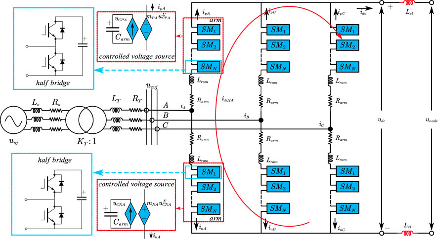
FIGURE 1. Structure of an MMC.
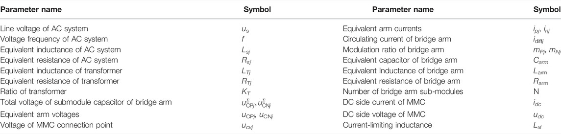
TABLE 1. Parameters of the MMC systems.
Since the proposed UMS for MMC systems is achieved in dq frame, the model proposed in this paper can be derived by transforming the dynamic average model built in ABC frame based on Park transformation and dynamic phasor theory. First, with MDM, the overall MMC system is partitioned into five parts (specifically, they are MMC internal electrical system, DC interface system, AC system, signal sampling filter, and controller) and modeled separately. Then, by configuring and connecting the input and the output of the state-space model of each system, we can obtain the nonlinear state-space model of the overall MMC system.
Since the MMC model established in this paper focuses on system operation and stability analysis without any consideration of AC or DC faults, the following assumptions are made for modeling MMC systems:
1) All three-phase components are symmetric; 2) The operations of the positive and negative arms of each phase are symmetric; 3) The modeling of a phase-locking loop (PLL) is not taken into account, because the voltage deviation of the point of common coupling (PCC) bus is diminutive during normal operation due to a relatively high ratio of short circuit of the AC system connected to MMC.
Remark 1. In order to reduce the complexity of the formula, the following formula derivation takes one phase as an example (j = A, B, C) and omits the subscript j representing three phases.According to Figure 1, the circulating current can be expressed as:
and
where Ce is the capacitance value of the submodule.The dynamic model of
where i=ip−inFor positive and negative bridge arms, the following equations can be obtained by KVL:
By Eq. 4 minus Eq. 5, the dynamic equation of the circulating current can be expressed as Eq. 6.
Add Eq. 4 to Eq. 5, the dynamic equation of the AC current can be expressed as Eq. 7.
Here, in Eq. 7, eMMC is as follows.
When the three-phase voltage of AC system is symmetrical, the components of voltage, current and modulation signal are relatively simple (Jamshidifar and Jovcic, 2016), us, ucv,
where the subscripts 0, 1, and 2 in the amplitudes (Us, Ucv, M1, M2, Idiff0, I, Idiff2, UCP0, UCP1, UCP2, UCN0, UCN1, and UCN2) and the initial phase angles (θs1, θcv1, θm1, θm2, θi1, θdiff2, θCP1, θCP2, θCN1, and θCN2) represent the zero sequence, the fundamental-frequency, and the second-order harmonic components, respecitvely; θ = ωt (ω is the grid fundamental frequency) is a synchronized phasor angle with the grid voltage.
To obtain the steady-state time invariants model of MMC, we need to transform variables us, ucv,
Thus, us, ucv,
where the variables with subscripts d and q represent the fundamental frequency components of the corresponding variables in dq reference frame; the variables with subscripts d2 and q2 represent second-order harmonic components of the corresponding variables in dq reference frame; the variables with subscript 0 represent the DC components of the corresponding variables in dq reference frame.
To obtain the sub-components’ dynamic equations of the variables
Remark 2. Due to space constraints, detailed substitution processes are omitted. The substitution process contains the product term like
where variables X and Y have the expressions in Eq. 16.
And in Eq. 15, the coefficients a, a0, ad, aq, ad2, and aq2 are as follows.
Additionally, another expression (Exp2) of
Finally, Exp1 and Exp2 are employed to build equations in which we let the corresponding terms equal to each other. And then we can get 10th order dynamic equations Eq. 19 of the MMC electrical system in dq reference frame as follows.
The model of MMC electrical system is sorted out into the state equation and the output equation as follows.
where state variables
Remark 3. In this paper, the state variables, the system’s inputs, and the system’s outputs in the state equations and output equations are represented by x, u, and y, respectively. And different subsystems are represented by the different subscripts and superscripts. The subscripts AC and MMC represent the AC system connected to the MMC and the MMC system except for the AC system, respectively; the superscripts ele, int, fil, and ctrl indicate the MMC internal electrical system, DC interface, signal filter, and controller, respectively. Besides, the input u and the output y are divided into several subvectors with the superscript notation to facilitate the modular splicing of each subsystem, respectively.
The DC interface of MMC is modeled to connect the MMC electrical system with the DC network conveniently. The DC interface of MMC is modeled as a controlled current source, whose output is idc (idc = 3idiff0). The MMC’s DC side input is the DC voltage connected to the DC network nodes. For decoupling, a virtual resistor Rn is introduced. As long as Rn is selected large enough, the DC network and the MMC electrical system can be decoupled without affecting the modeling accuracy of the system (Pogaku et al., 2007). Besides, when a failure occurs to the DC side, the DC interface of MMC is usually connected with the current limiting reactance in series to prevent a large fault current impact. Finally, the equivalent circuit of the DC interface is shown in Figure 2.
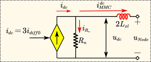
FIGURE 2. DC interface of MMC.
According to the equivalent circuit in Figure 2, its dynamic equation is expressed as Eq. 21.
where
The model of the DC interface is sorted out into the dynamic equation and the output equation, which are expressed as follows:
where state variables
As to the modeling of AC system, a virtual resistor is also used to decouple the AC system from the MMC electrical system. The AC system in Figure 1 is reduced to the one shown in Figure 3. In Figure 3,
where idAC and iqAC are d-axis current and q-axis current of AC system in dq reference frame, respectively; usd is equal to the phase voltage amplitude of the AC grid and usq = 0 if the grid voltage directional control is adopted.
FIGURE 3. Equivalent circuit of AC system.
The model of AC system is sorted out as Eq. 24.
where state variables
The input signals of the MMC controller are the measurement signals of MMC’s parameters. There is noise and interference in the actual measurement, and signals need to be filtered and then sent to the controller. Therefore, the modeling and analysis of the signal filter are required. In this paper, the first-order low-pass filter as shown in Figure 4 is used, and the dynamic equations of the filters are expressed as Eq. 25.
where cut-off frequency
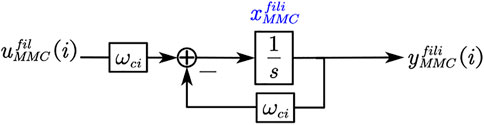
FIGURE 4. Principle diagram of filter.
The model of filters is sorted out as Eq. 26.
where state variables
The controller plays a decisive role in the dynamic behavior of MMC. The double closed-loop vector control strategy based on dq reference frame, which is a standardized control mode of MMC, can realize the decoupling of active and reactive power. Therefore, in this paper, the controller is modeled in the dq reference frame. Since MMC usually contains multiple control modes which need to be switched with the changes of the operation state of AC/DC power grids, this paper uses the unified modeling method for MMC’s controller to simplify the modeling and realize the normalization of the controller model. Thus, remodeling the MMC systems is avoided when the MMC’s control modes need to be changed, increasing the flexibility of modeling the AC/DC power grids. Different control modes can be selected in the unified model by configuring control mode variables, avoiding the inconvenience of modeling the MMC separately for different control modes. Figure 5 is the diagram of the controller using unified modeling, and Table 2 shows the configuration of the control mode variables for different MMC control modes.
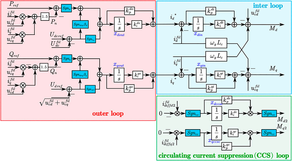
FIGURE 5. Diagram of controller.
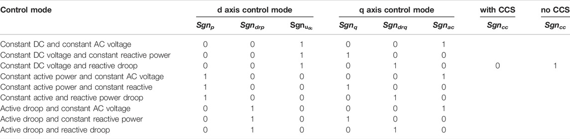
TABLE 2. Configuration of control modes.
In Figure 5, Udcref, Udref, Pref, and Qref are the references of DC voltage, AC voltage, active power, and reactive power, respectively. xdin, xdout, xqin, xqout, xdcsc, and xqcsc are the states of the integrators.
According to the diagram of the unified controller, its state equation and output equation are expressed as Eq. 27.
The model of the unified controller is sorted out as Eq. 28.
where
According to Eq. 20, Eq. 22, Eq. 24, Eq. 26, Eq. 28, we can establish the relationships of the input and output among subsystems as follows:
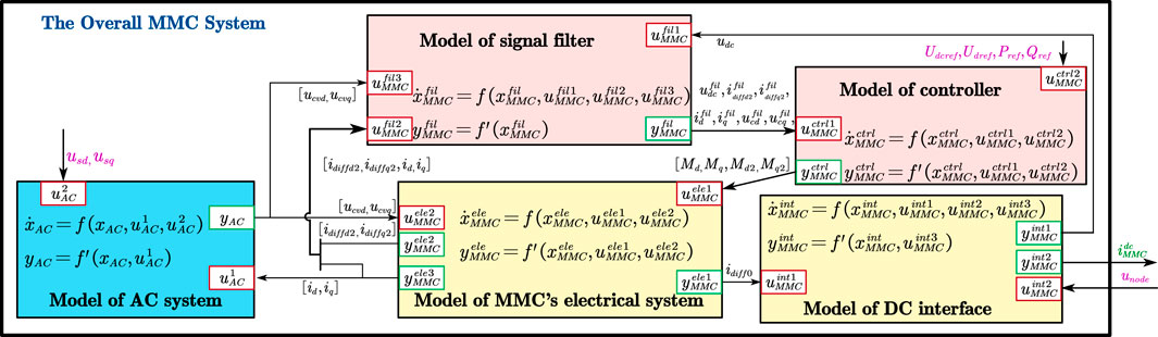
FIGURE 6. Model of the overall MMC system with the MDM.
The MDM makes modeling MMC systems more expansible to adapt to different hybrid AC/DC power grids. For example, if one of the subsystems of the MMC systems needs to be changed, we only need to remodel the subsystem rather than the entire MMC system. Besides, due to decoupling and modularizing the MMC systems, the small-signal model of the overall MMC system could be developed directly through linearizing and splicing proposed model, which enables our model to analyze the small-signal stability of large-scale hybrid AC/DC power grids.
For purposes of validation, a simulation system is shown in Figure 7. The system consists of an AC system, an MMC, and a resistive load. To verify the accuracy and superiority of the established model, we compared the proposed model with D-EMT and AVE-EMT models by the simulation test system. Table 3 and Table 4 list the system parameters and control parameters, respectively.
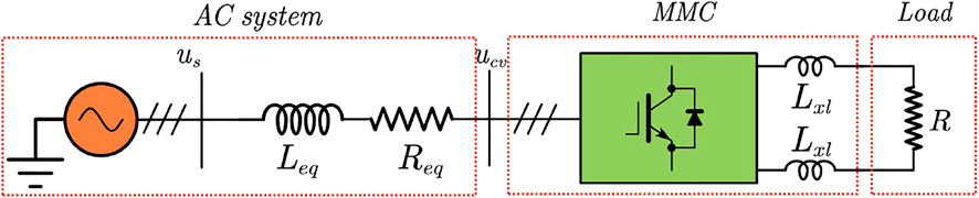
FIGURE 7. Simulation test system of the overall MMC system.

TABLE 3. Parameters of the MMC systems.
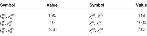
TABLE 4. The control parameters.
Here, we set the control modes of MMC as constant DC voltage and constant reactive power, and the dynamic response under load mutation and control instruction step are compared under closed-loop control. The working condition is set as follows: at 2 s, a load with a resistance of 100 Ω is suddenly put into; at 3 s, the resistance increases from 100 Ω to 200 Ω; at 4 s, the DC voltage steps from 1 pu to 1.05 pu; at 5 s, the DC voltage steps from 1.05 pu to 1 pu.
The per-unit (pu) wapveforms of udc, idc, id, iq, ucvd, and ucvq are shown in Figures 8–13. By testing the above working conditions, it can be seen from these figures that the accomplished state-space model of overall MMC system is highly consistent with the detailed electromagnetic transient model and the average electromagnetic transient model. The accuracy and validity of the proposed modeling method are verified.
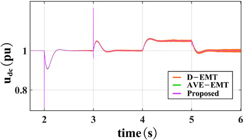
FIGURE 8. Per-unit waveform of udc.
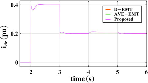
FIGURE 9. Per-unit waveform of idc.

FIGURE 10. Per-unit waveform of id.
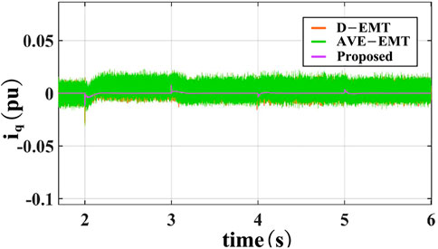
FIGURE 11. Per-unit waveform of iq.
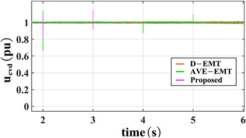
FIGURE 12. Per-unit waveform of ucvd.
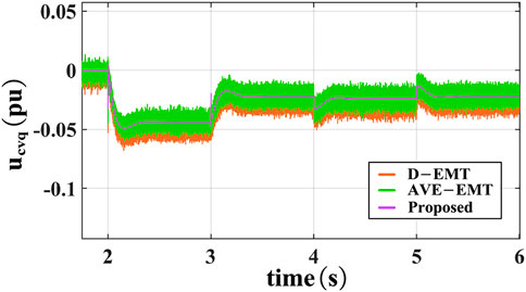
FIGURE 13. Per-unit waveform of ucvq.
In addition, Table 5 shows the comparison results of the actual simulation time of the three models. It is at least 59.8 times more efficient than the D-EMT and 4.6 times more efficient than the AVE-EMT for the same simulation conditions. Therefore, the proposed model greatly accelerates the simulation speed while obtaining high precision.
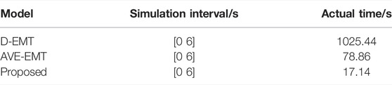
TABLE 5. Comparison results of the actual simulation time.
A unified modeling scheme (UMS) for MMC systems in a synchronous (dq) reference frame is proposed in this paper. A simulation test system verifies our model in MATLAB/Simulink.
(1) The modular decouple modeling (MDM) and the unified controller modeling make modeling MMC systems more flexible and expansible to adapt to different hybrid AC/DC power grids.
(2) The proposed model shows an accurate replication to the dynamic performance of the EMTs (D-EMT and AVE-EMT) model.
(3) The proposed model greatly reduces the simulation time. For the same simulation conditions, it is at least 59.8 times more efficient than the D-EMT and 4.6 times more efficient than the AVE-EMT. Therefore, our model is suitable for simulating the large-scale hybrid AC/DC power grids.
(4) The small-signal model of the overall MMC system could be developed directly by linearizing and then splicing proposed model. Therefore, the proposed model is suitable for studying the stability of small-signal.
The original contributions presented in the study are included in the article/Supplementary Material, further inquiries can be directed to the corresponding author.
XX: Writing—original draft and Writing—review. ZW and QH: Conceptualization. XQ, XD, and XC: Formal analysis and revision.
This work is supported in part by National Natural Science Foundation of China under Grant 51867016, in part by National Key R&D program of China under Grant 2018YFB0904700.
The authors declare that the research was conducted in the absence of any commercial or financial relationships that could be construed as a potential conflict of interest.
All claims expressed in this article are solely those of the authors and do not necessarily represent those of their affiliated organizations, or those of the publisher, the editors and the reviewers. Any product that may be evaluated in this article, or claim that may be made by its manufacturer, is not guaranteed or endorsed by the publisher.
Antonopoulos, A., Angquist, L., and Nee, H.-P. (2009). “On Dynamics and Voltage Control of the Modular Multilevel Converter,” in 2009 13th European Conference on Power Electronics and Applications, Barcelona, Spain, September 08-10, 2009, 1–10.
Deore, S. R., Darji, P. B., and Kulkarni, A. M. (2012). “Dynamic Phasor Modeling of Modular Multi-Level Converters,” in 2012 IEEE 7th International Conference on Industrial and Information Systems (ICIIS), Chennai, India, August 06-09, 2012, 1–6. doi:10.1109/ICIInfS.2012.6304792
Gnanarathna, U. N., Gole, A. M., and Jayasinghe, R. P. (2011). Efficient Modeling of Modular Multilevel Hvdc Converters (Mmc) on Electromagnetic Transient Simulation Programs. IEEE Trans. Power Deliv. 26, 316–324. doi:10.1109/tpwrd.2010.2060737
Harnefors, L., Antonopoulos, A., Norrga, S., Angquist, L., and Nee, H.-P. (2013). Dynamic Analysis of Modular Multilevel Converters. IEEE Trans. Ind. Electron. 60, 2526–2537. doi:10.1109/TIE.2012.2194974
Ilves, K., Antonopoulos, A., Norrga, S., and Nee, H.-P. (2012). Steady-state Analysis of Interaction between Harmonic Components of Arm and Line Quantities of Modular Multilevel Converters. IEEE Trans. Power Electron. 27, Structure of an MMC. 57–68. doi:10.1109/TPEL.2011.2159809
Jamshidifar, A., and Jovcic, D. (2016). Small-Signal Dynamic DQ Model of Modular Multilevel Converter for System Studies. IEEE Trans. Power Deliv. 31, 191–199. doi:10.1109/TPWRD.2015.2478489
Jovcic, D., and Jamshidifar, A. (2015). “Phasor Model of Modular Multilevel Converter with Circulating Current Suppression Control,” in 2015 IEEE Power Energy Society General Meeting, Denver, CO, USA, July 26-30, 2015, 1. doi:10.1109/PESGM.2015.7286104
Li, Y., Tang, G., Ge, J., He, Z., Pang, H., Yang, J., et al. (2018). Modeling and Damping Control of Modular Multilevel Converter Based Dc Grid. IEEE Trans. Power Syst. 33, 723–735. doi:10.1109/TPWRS.2017.2691737
Liu, S., Xu, Z., Hua, W., Tang, G., and Xue, Y. (2014). Electromechanical transient modeling of modular multilevel converter based multi-terminal hvdc systems. IEEE Trans. Power Syst. 29, 72–83. doi:10.1109/TPWRS.2013.2278402
Munch, P., Liu, S., and Dommaschk, M. (2009). “Modeling and Current Control of Modular Multilevel Converters Considering Actuator and Sensor Delays,” in 2009 35th Annual Conference of IEEE Industrial Electronics, Porto, Portugal, November 03-05, 2009, 1633–1638. doi:10.1109/IECON.2009.5414756
Peralta, J., Saad, H., Dennetiere, S., Mahseredjian, J., and Nguefeu, S. (2012). Detailed and Averaged Models for a 401-level Mmc-Hvdc System. IEEE Trans. Power Deliv. 27, 1501–1508. doi:10.1109/TPWRD.2012.2188911
Pogaku, N., Prodanovic, M., and Green, T. C. (2007). Modeling, Analysis and Testing of Autonomous Operation of an Inverter-Based Microgrid. IEEE Trans. Power Electron. 22, 613–625. doi:10.1109/TPEL.2006.890003
Saad, H., Guillaud, X., Mahseredjian, J., Dennetiere, S., and Nguefeu, S. (2015). Mmc Capacitor Voltage Decoupling and Balancing Controls. IEEE Trans. Power Deliv. 30, 704–712. doi:10.1109/TPWRD.2014.2338861
Sanders, S. R., Noworolski, J. M., Liu, X. Z., and Verghese, G. C. (1990). Generalized Averaging Method for Power Conversion Circuits. 21st Annual IEEE Conference on Power Electronics Specialists, San Antonio, TX, USA, June 11-14, 1990, 333–340. doi:10.1109/PESC.1990.131207
Sun, P., Jiao, Z., and Gu, H. (2021). Calculation of short-circuit current in dc distribution system based on mmc linearization. Front. Energy Res. 9, 26. doi:10.3389/fenrg.2021.634232
Trinh, N.-T., Zeller, M., Wuerflinger, K., and Erlich, I. (2016). Generic Model of Mmc-Vsc-Hvdc for Interaction Study with Ac Power System. IEEE Trans. Power Syst. 31, 27–34. doi:10.1109/TPWRS.2015.2390416
Vatani, M., Hovd, M., and Saeedifard, M. (2015). Control of the Modular Multilevel Converter Based on a Discrete-Time Bilinear Model Using the Sum of Squares Decomposition Method. IEEE Trans. Power Deliv. 30, 2179–2188. doi:10.1109/TPWRD.2015.2412151
Wang, W., Wang, L., Zhu, B., Li, G., Xin, Y., and Jiang, S. (2021). Power decoupling control of mmc and small-signal stability analysis of ac/dc distribution network with renewable energy. Front. Energy Res. 9, 170. doi:10.3389/fenrg.2021.660236
Xianyong, Z., Zijuan, G., Yaohong, H., Li, L., Weikuan, P., and Jian, C. (2021). Power decoupling control of mmc and small-signal stability analysis of ac/dc distribution network with renewable energy. Front. Energy Res. 9, 465. doi:10.3389/fenrg.2021.734797
Zhao, J., and Tao, Y. (2021). Control characteristic analysis and coordinated strategy design for hybrid hvdc with multi-infeed mmc inverters. Front. Energy Res. 9, 558. doi:10.3389/fenrg.2021.737294
Keywords: MMC, virtual resistor, module decouple connection method, small signal, MMC modeling, AC/DC power grids
Citation: Xie X, Wu Z, Hu Q, Quan X, Dou X and Cao X (2022) A Unified Modeling Scheme of Modular Multilevel Converter for Hybrid AC/DC Power Grids. Front. Energy Res. 10:844713. doi: 10.3389/fenrg.2022.844713
Received: 28 December 2021; Accepted: 21 January 2022;
Published: 13 April 2022.
Edited by:
Kaiqi Sun, Shandong University, ChinaReviewed by:
Yizhen Wang, Tianjin University, ChinaCopyright © 2022 Xie, Wu, Hu, Quan, Dou and Cao. This is an open-access article distributed under the terms of the Creative Commons Attribution License (CC BY). The use, distribution or reproduction in other forums is permitted, provided the original author(s) and the copyright owner(s) are credited and that the original publication in this journal is cited, in accordance with accepted academic practice. No use, distribution or reproduction is permitted which does not comply with these terms.
*Correspondence: Zaijun Wu, emp3dUBzZXUuZWR1LmNu
Disclaimer: All claims expressed in this article are solely those of the authors and do not necessarily represent those of their affiliated organizations, or those of the publisher, the editors and the reviewers. Any product that may be evaluated in this article or claim that may be made by its manufacturer is not guaranteed or endorsed by the publisher.
Research integrity at Frontiers
Learn more about the work of our research integrity team to safeguard the quality of each article we publish.