 Hossein Torabi-Monfared
 Mohammad Mahdi Doroodmand*
- Department of Chemistry, College of Sciences, Shiraz University, Shiraz, Iran
The extraordinary claim of observing nuclear fusion products and excess heat during heavy water electrolysis at room temperature was sensationalized in 1989. Unfortunately, it was rejected quickly by scientific communities. At the last attempt to access the accuracy of the previous works in this field, a Google-funded team tried to examine all reported works with their corresponding conditions to confirm the claimed results. Finally, they found that there was no reasonable proof of nuclear fusion reactions under the reported conditions. Here, we introduced a method to apply a unique triggering potential waveform to a simple two micro-shaft system in both heavy and light concentrated salinity waters which resulted in detecting 4-helium, gamma rays, and heat repeatedly and reproducibly. In this work, two types of nuclear fusion reactions were observed: 1) A D + D fusion reaction in potassium halide salt solutions in heavy water and 2) a new type of fusion reaction in carbon-containing salt solutions in both light and heavy waters. In the latter type, it was proved that the existence of carbon atoms in an anion structure is critical to observe the 4-helium, gamma rays, and heat.
1 Introduction
Using the term “cold fusion” in scientific reports dates back to the 1950s to describe muon-catalyzed fusion (Laurence, 1956; Rafelski and Jones, 1987), but the main and inextricable application of this term is now to describe a wonderful scientific claim sensationalized in 1989 by two electrochemists, Martin Fleischmann and Stanley Pons, from Utah University (Fleischmann and Pons, 1989). They claimed that the generated thermal energy in heavy water electrolysis using a Pd cathode exceeded the energy produced by all known chemical reactions in those conditions. Due to the importance of this claim, this clean, abundant, and inexpensive energy source motivated other scientists to accurately repeat it. Unfortunately, the claimed results by Fleischmann and Pons about anomalous heat and nuclear fusion products were not pertinently certified, and therefore the phenomena were quickly rejected by the scientific community (Miskelly et al., 1989; Williams et al., 1989; Albagli et al., 1990; Maddox, 1990). These events caused scientists to invalidate this subject in academic research. Furthermore, during the last 32 years, attempts have been unsuccessful in attaining a reliable method or experiment that can generate repeated and reproducible heat and nuclear reaction products. In the last attempt in this field, a research team in 2015 started a comprehensive study, funded by Google Co., about the accuracy of the reported claims in this field (Berlinguette et al., 2019). The obtained results of this research team over 3 years showed no evidence that cold fusion is possible based on all previously reported conditions. Here we found that using a triggering potential waveform (TPW) as the driving force led to various gases evolving on the surface of only one micro-shaft of a simple two-micro-shaft system in a concentrated KCl solution (1.0 mol L−1). This phenomenon with the same set-up, in addition to the concentrated KCl solution, was also observed in another 20 randomly selected salts with similar concentrations (1.0 mol L−1) in both light and heavy waters. Under the same condition for all tested salts, 4-helium (4-He) evolution, gamma-ray (γ-ray) radiation, and heat were detected during the use of some of the above salts. It was concluded that these observations were related to the D + D fusion reaction and a new kind of reaction. An important observation during all conducted experiments was that no current flow through the system was observed. In addition, all gases were surprisingly evolved on the same micro-shaft except for phosphate salt where a jelly compound instead of gas was generated on the surface of that micro-shaft.
2 Experimental
2.1 Materials and Solutions
In this study, all the reagents were of analytical grade and used without any further treatments. KF (>99%, Merck Company, Germany), KCl (>99.9%), KBr (>99.9%), KI (>99.0%), NaCl (>99.9%), NaI (99%), KHCO3 (99.5%), K2CO3 (>99%), KNO3 (99.0%), Fe(NO3)2 (>99%), Ca(NO3)2 (>99%), NaNO3 (>99.5%), K2SO3 (>98%), CH3COOK (>99%), CH3COONa (99%), (CH3COO)2Mg (99.0%), (CH3COO)2Co (>98.5%), (CH3COO)2Fe (>98.5%), (CH3COO)2Cd (>99%), and K3PO4 (≥98%) were all purchased from the Merck company.
Standard gases of N2 (99.995%, Parsballon Company, Iran), CH4 (>98%, humidity, 0.8%, Parsballon Company, Iran), SO2 (99.99%, Parsballon Company, Iran), CO2 (98%, Parsballon Company, Iran), NO2 (99.95%, Linde Company), H2 (99.99%, Ardestani Company, Isfahan, Iran) O2 (99%, Ardestani Company, Isfahan, Iran), and He (99.95%, Linde Company) were purchased from the mentioned companies. Ultra-analytical grades of light water-free D2O, HPLC-grade light water, acetonitrile, and methanol solvents were purchased from Merck Co., Germany. Formaldehyde solution (37%, weight/weight percent (W/W)) was purchased from the Sigma-Aldrich company. A 10.0 cm high and 2.0 mm diameter tungsten carbide (WC) alloy rod (WC + 6–10 Wt. % Co) was purchased from Shanghai TQMC Mining and Construction Machinery Co., China. The short form of WC instead of a WC-Co alloy was used through this work. Some stainless steel pins were purchased from a local market in Shiraz City, Fars Province, Iran.
2.2 Tungsten Carbide Micro-shaft Fabrication
Electrochemical anodization was used to fabricate WC micro-shafts. A high current electro-analyzer (potential range: ±50.00 V (vs. GND), electrical current sensitivity between µA- A, scan rate in the range of 10–2000 mV s−1, and electrical current accuracy up to a maximum of 0.53%) with a maximum potential drift of 53 mV (vs. GND, after approximately 2 h) based on a two-electrode system including a commercial WC (diameter: 2.0 mm, height: 3.0 cm) and stainless steel (type: 308, diameter: 2.0 mm, height: 10.0 cm) shaft with an inter-electrode distance of 4.0 cm as the anode and cathode electrodes, respectively, was used. To fabricate the micro-shaft, 1.0 cm of the WC shaft was immersed inside the mixture of a concentrated acidic solution including H2SO4 (98%, W/W), HClO4 (70%, W/W), and triple-distilled water with an optimum volume percentage of 4:12:84, respectively, as the electrolyte with a total volume of 25.0 ml. To anodize, a special optimum two-step waveform was applied to the system to fabricate the micro-shaft. Each cycle of this potential waveform consisted of two steps: 1) the first step was a + 3.5 V potential (vs. total applied potential) called anodizing voltage applied for 40 s. 2) The second step was a cyclic potential sweep with a high scan rate (
2.3 Set-Up System and Wave Generation
To analyze, a closed cylindrical polytetrafluoroethylene (PTFE) container (10.0 cm3) was designed so that one micro-shaft was placed in the center of the container and the other micro-shafts (four and more depending on the interested analysis) were put around the central micro-shaft. The distance between each micro-shaft was fixed at 1.0 cm. All micro-shafts were immersed in solution to a fixed height (0.5 cm). The volume of the solution above was estimated to be
To generate the applied wave, a new function generator able to generate a specific potential signal was designed. Each cycle of the generated potential signal wave (2,442 µs) consisted of three different parts: a constant trigger signal (72.0 mV vs. total applied potential, time duration: 18 µs), a ULF-ranged reverse exponentially decayed trigger potential signal (freq: 2,810 Hz, initial potential: 32 mV vs. total applied potential, the percentage of decay: %12), and a different phase angle (−15°) against the end of the positive surface of the asymmetric square wave and asymmetric square wave (off/on potential levels: 64 and 0 mV, respectively; off/on time durations: 33 and 74 µs, respectively). During the off-time duration of the asymmetric square wave, the trigger potential was also off. The time delay between each cycle was estimated to be 270 µs. Then, these three parts were mixed to produce the complete special potential signal wave. In each cycle, at the first positive surface of the asymmetric square wave, only the constant trigger potential was applied, and at the next positive surface, the trigger potential was applied. This specific potential wave was applied parallel to the micro-shafts positioned around the center micro-shaft for over 1 h. All parts of the system were situated inside a closed cylindrical Pb (purity: > 99.9%) container. A Faraday cage was utilized to eliminate any probable noise source during the data acquisition process.
2.4 Identification of Generated Products in the Gas Phase
First, the gas chromatography-thermal conductor detector (GC-TCD) (Shimadzu, Japan, Nexis SCD-2030) instrument was calibrated by using standard gases including H2, CO2, CH4, O2, He, NO2, and SO2. Before each injection, the given values of the above-mentioned gases were mixed and diluted up to 10.0-fold excess through the alternative mass flow controller (MFC) and N2 gas supply. An open tubular (capillary) GC column was made of OV-17 (50% diphenyl, 50% dimethylpolysiloxane, Ohio Valley Specialty Company, internal diameter (ID) of 300 μM, length: 30 m) as the stationary phase and Ar as the mobile phase with a 65% split. The temperature program was as follows: initial temperature: 30°C, initial time: 5.0 min, temperature ramp: 15°C min−1, final temperature: 120°C, and final time: 10.0 min. Each gas analysis was achieved via the off-line introduction of the gas solution using a silica micro-filter and a modified gas tight Hamilton syringe (1.0 ml). Sampling was conducted at every 1.0 h interval after applying the TPW. It should be kept in mind that all the following analyses took place in seven selected salt solutions: potassium halide salt, potassium carbonate, bicarbonate, and bicarbonate salt. All solutions in both solvents were prepared in the same concentration (1.0 mol L−1).
2.5 Identification of Generated Products in Solution
To determine the type of generated compounds in the solutions, the headspace method was used. To do this, the solution (20.0 ml) was heated inside a closed balloon (25.0 ml) at approximately 60°C for 15.0 min. And then the collected sample was injected directly to a gas chromatography/quadrupole time-of-flight mass spectrometry (GC/Q-TOF, mode: NICI-SIM, model: Shimadzu, Japan) system. High-performance liquid chromatography (HPLC) (Waters HPLC Alliance 2,695) was selected for the water (H2O and D2O) analysis using a UV-Vis (λmax = 270 nm) spectrophotometer as a detector. The stationary phase included a 25-cm C18 column and acetonitrile: water (initial matrix: 70:30, volume/volume percent (V/V), initial time: 10.0 min, mobile phase gradient of 1.0 V/V per min−1, final solvent gradient 50:50, V/V, final time: 15 min) at pH 7.0 using 0.l mol L−1 of phosphate buffer solution with a mobile phase gradient. To be sure, the reliability of the peak at a certain retention time was evidenced via spiking the sample with formaldehyde and methanol (10.0 parts per million, ppm, 1.0 ml) to the initial tested solution (10.0 ml), along with evaluation of the retention times and the peak areas of each peak.
2.6 Gamma-Ray Detection
The gamma rays were detected using an XR-100CdTe X-ray and gamma-ray detector. This detector was pre-amplified using a CdTe diode, followed by pulse counting using a digital pulse processor (PX5). Due to the size limitation of the γ-ray probe, a closed 50.0 ml cubic PTFE container containing 25.0 ml of solution was used. The position of the micro-shafts was similar to the above experiment. The 1.0 mol L−1 solutions of potassium halides and carbon-containing salts in heavy water and carbon-containing salts in light water were prepared for this step.
The probe was placed on top of the solution in the middle of the container at a distance as high as 1.0 cm from the surface of the solutions. The time-domain data of γ-ray radiation was measured during the sequence applying the potential waveform to the two micro-shafts for 2.0 s after turning on the wave generator, and also 4 s after turning off the TPW. The average of the frequency domain during 1.0 h of operation was estimated to be around 500. To acquire the frequency domain of γ-ray, Laplace transformation was used. To measure the dissolved oxygen, the calibrated dissolved oxygen (DO) meter’s probe was immersed into solution for 1.0 h. Due to the size limitation of the DO-meter, the container used to detect gamma rays was employed.
2.7 Neutron Imaging
To evaluate the neutron radiation, a standard scintillation screen for neutron imaging [base material: 6LiF/Zn(Cd)S: Ag (ratio 1/2), emission wavelength: 605 nm (orange), dimension: 100 × 50 mm, thickness: 100 μm, RC TRITEK Ltd., Switzerland] was adopted. For this purpose, this film was situated in the interior space of the PTFE container near to the solution and the physical changes were followed qualitatively at different time intervals using a high-resolution charge-coupled device camera (Kodak KAI-11002, United States resolution: 11 million pixels) and analyzed through a program written in the Visual Basic 6 (VB6) program.
2.8 Identification of 4-He and D2
To identify 4-He and D2, at first, the generated gases of the solution above in heavy water were passed over a new catalyst (the corresponding paper is currently being written) to remove the D2 gas as D2O. The He was detected by a residual gas analyzer (RGA) during direct sampling and introducing 100 µl using a micro syringe. For quantitative analysis, the peak areas of the GC-TCD chromatogram with and without D2 were used to calculate the value of He and D2.
2.9 Calorimetric Heat Detection
To estimate the heat of the salt solution, while applying the TPW to the WC micro-shafts, the bomb container of the calorimeter was selected as the container, and all parts of the system were situated inside the calorimeter according to the procedures reported based on the Seebeck calorimeter methodology (Storms, 2007). The electrical connections were also achieved using BNC connectors through the Ni-Cr thermocouple (Type: K) and the thermal gradients were measured versus time during at least 24 h time intervals. It should be noted that to avoid the reduction of the solution volume due to the vaporization process during the 24 h time interval, it was controlled using a water level controller (model: Blackt Electrotech, BT21CSP). The vaporized solution in each analysis was compensated by an isothermal solution added by a peristaltic pump (model: LP-BT100-2J). All of these steps were controlled automatically.
3 Results and Discussion
Figure 1 presents a schematic view of the applied TPW, each cycle of which consists of a constant trigger pulse wave signal, exponentially amplitude-decayed trigger pulse wave signals, and an asymmetric square wave. The combination of these components in each cycle generated a unique potential waveform which when applied to a simple two micro-shaft (100 µM) system, containing various concentrated solutions, generated a special environment on the surface of either micro-shaft to encourage different reactions on the surface of both micro-shafts with no detectable current flowing through the system.
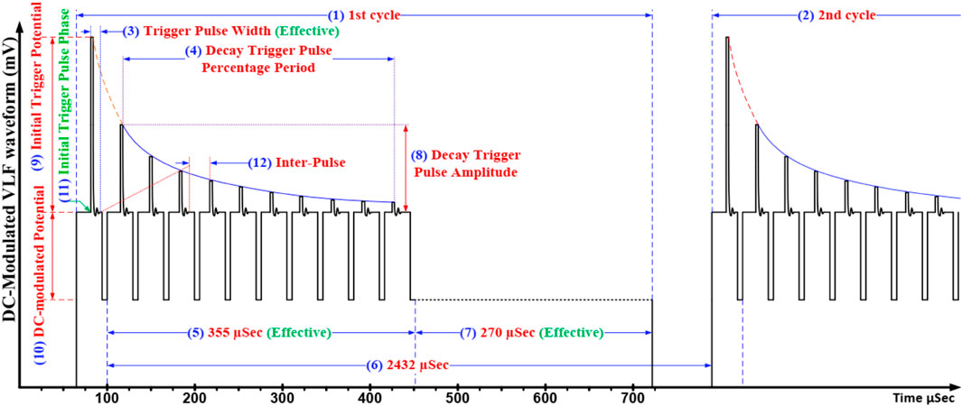
FIGURE 1. Scheme of the TPW with all parameters. 1) 1st cycle, 2) 2nd cycle, 3) trigger pulse width (effective) (µs), 4) decay trigger pulse percentage period (%), 5) modulated period (effective) (µs), 6) whole period (µs), 7) cut-off time (effective) (µs), 8) decay trigger pulse amplitude (mV), 9) initial triggered potential (mV), 10) DC-modulated potential (mV), 11) initial phase (o), and 12) inter-pulse (µs).
The FE-SEM images of the used micro-shaft in Figure 2 show the completely rough surface of the electrochemically fabricated micro-shaft. The presence of a great deal of porosity on the surface of all fabricated micro-shafts is related to electrochemically dissolving Co metal, used as the binder, faster than WC from the bulk of the WC-Co composite. The various sizes of these porosities and also the sharp tip protrusion with different sizes on the micro-shaft surface were attributed to the employment of an electrochemically coarse method to fabricate the micro-shaft.
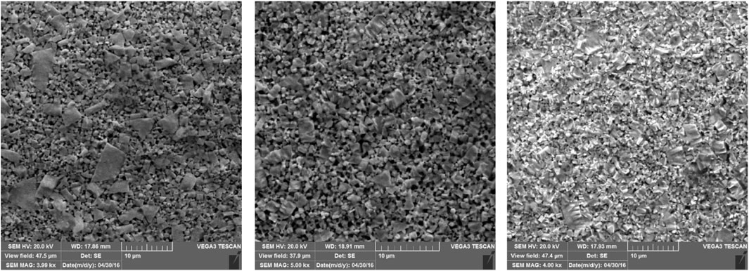
FIGURE 2. The morphology of three different micro-shafts.
The ability of this method to induce other possible reactions with the same set-up was assessed for 20 different solutions prepared using randomly selected inorganic salts. The qualitative results of evolved gases in the examined solutions by GC-TCD are summarized in Table 1 (Figure 3). In contrary to the expectations, the type of the evolved gases for some salts completely depended on the structural elements of anions (Figure 3 and Supplementary Table S1). The other main important property of all tests was the lack of current flow through the system. Therefore, according to the evolved gases in each solution, the employed salts could be divided into five groups. Apart from group A in light water, including the only hydrogen and oxygen gases, the other groups had at least one non-metal oxide gas whose non-metal elements were present in the anion structure of their corresponding salts. Despite the presence of the same non-metal oxide gas (CO2) in both B and C groups, the difference of these two groups refers to the evolution of methane gas in the solutions of the acetate salts. Above all, among the evolved gases in all subclasses of light water, the presence of helium gas attracted more attention due to its origin on the Earth. To assess the type of the evolved gases in heavy water, all the above experiments with the same set-up were repeated in heavy water. Besides the generation of overall heavy water splitting products (D2 and O2 gases), some differences in comparison with light water were observed. First, the evolution of helium gas in group A was detected in addition to the overall heavy water splitting products (D2 and O2 gases), while no additional gas was added to the other groups. In this case, a residual gas analyzer (RGA) was used to differentiate between the production of He and D2 gases. The other difference was related to the detection of mono-deuterated methane gas (CH3D) in group C. Considering the above observations and also the importance of the existence of He gas in the detected gases, seven potassium salts of halides, carbonate, bicarbonate, and acetate were selected for further study. It must be noticed that during all the above reactions, no current was detected during all gas evolutions. This observation is not consistent with the nature of a thermodynamically uphill reaction requiring enough generated external energy, that is, the probability of involving an electrochemical process in these reactions is very low.
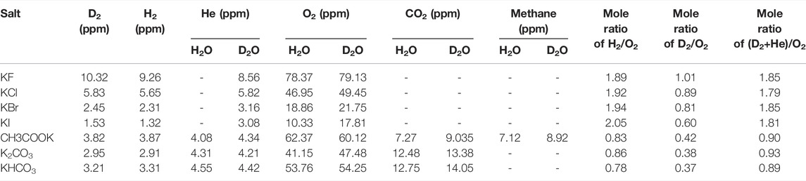
TABLE 1. Quantitative analysis of generated gases in seven selected salts in both solvents.
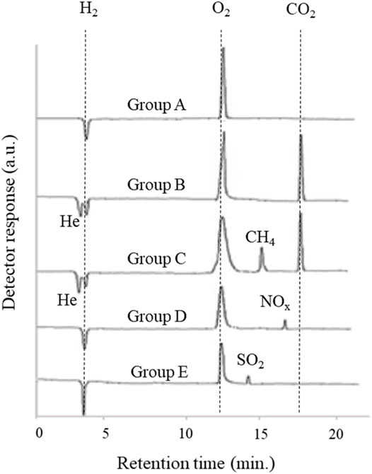
FIGURE 3. Released gases in five groups of salts in H2O.
The quantitative analysis of the produced gases in these seven salts in both solvents (Tables 1, 2) showed that although the variation of halide anions in both solvents significantly influenced the amount of all produced gases, the generated gases in these salts decreased in this order: KF > KCl > KBr > KI, and the variation of anions in the three carbon-containing salts showed no remarkable difference in the amount of generated gases.
TABLE 2. Released nuclear fusion products in seven selected salts in both solvents.
To precisely measure the generated gases, contrary to the salt-out effect, the amount of the possible dissolved gases was assessed (Supplementary Table S2) for all evolved gases. Among the generated gases, only the amount of dissolved oxygen gas showed a significant difference before and after the experiment. It is clear that the dissolved oxygen capacity of the solutions in which He gas was detected, especially in carbon-containing salt solutions in both solvents, enhanced remarkably. For this reason, to calculate the precise concentration of produced oxygen gas in these salts, the gaseous and dissolved oxygens were summed together. This observation in solutions motivated us to further analyze the solutions to find the other possible soluble compounds. Toward this end, the solutions of the seven salts were analyzed by GC-MS and HPLC in both H2O and D2O. Surprisingly, the results of the acetate solution analysis in both solvents after applying the TPW showed the production of formaldehyde (H2CO and D2CO in H2O and D2O, respectively) and methanol (CH3OH and CH3OD in H2O and D2O, respectively) (Figure 4), while no products were detected in other salts, especially potassium carbonate and bicarbonate solutions. The existence of the–CH3 group in deuterated methanol and -methane confirmed that this group originated from the decomposition of the acetate anion. The lack of other sources of the
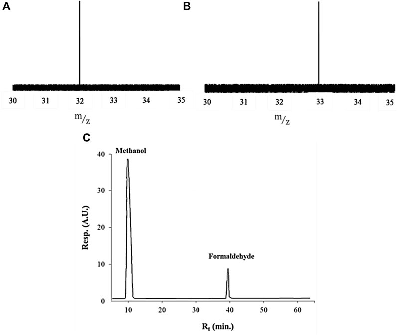
FIGURE 4. Identification of generated products in acetate solution prepared in both solvents. (A) GC-MS spectra of D2CO between 30–35 (m/z), (B) GC-MS spectra of CH3OD between 30–35 (m/z), and (C) HPLC chromatogram of formaldehyde and methanol.
3.1 Nuclear Production
Although the lack of γ-ray detection along with 4-He has been one of the main reasons to reject the previous research in the field of cold fusion, the simultaneous existence of 4-He and γ-ray was repeatedly and reproducibly detected in our work. γ-ray radiation, as a main direct observation of the nuclear process, was obtained in all suspected solutions in terms of count vs. time by using a γ-ray detector, and then frequency domain results (spectra) were calculated in terms of MeV by using discrete Laplace transformation (Table 3). The existence of γ-rays with an energy value of approximately 24 MeV in all potassium halide salts solutions in D2O along with 4-He is an appropriate reason to accept the D + D → 4-He + γ reaction as the prominent reaction in these solutions despite the fact that the possibility of this reaction in a theoretical nuclear physics viewpoint is extremely low (Laurence, 1956; Rafelski and Jones, 1987; Salamon et al., 1990; Berlinguette et al., 2019). On the other hand, comparing the mole ratios of H2/O2 in H2O and D2/O2 in D2O shows that the mole ratio of D2/O2 in all solutions of the halide salts deviated from the expectations. This deviation for the KI solution was more than that of three other salts. While, due to the same reaction conditions for both solvents, it was speculated that both solvents exhibited similar behaviors. Then the reduction of the mole ratios of D2/O2 for potassium halide salts in D2O with respect to being close to the amount of O2 gas in both solvents could be attributed to losing the D2 gas. The helium production in D2O as the main difference of the generated gases in both solvents in the solutions of halide salts could be the best candidate for losing the D2 gas. Surprisingly, the summation of the mole of D2 and He gases with each other caused the mole ratios of (D2 + He)/O2 for the four halide salts to approach 2 as expected, which were similar to mole ratios of H2/O2 for halide salts in H2O. Considering that the solvents are the only source of hydrogen isotopes (H and D atoms) and oxygen atoms in the solutions of halide salts, it seems that light and heavy waters were completely atomized and then recombined to generate the evolved gases. Due to the detection of these gases in other salt solutions in both solvents, it can be said that overall water splitting occurs through radical decomposition in all tested solutions without any current flow through the system.
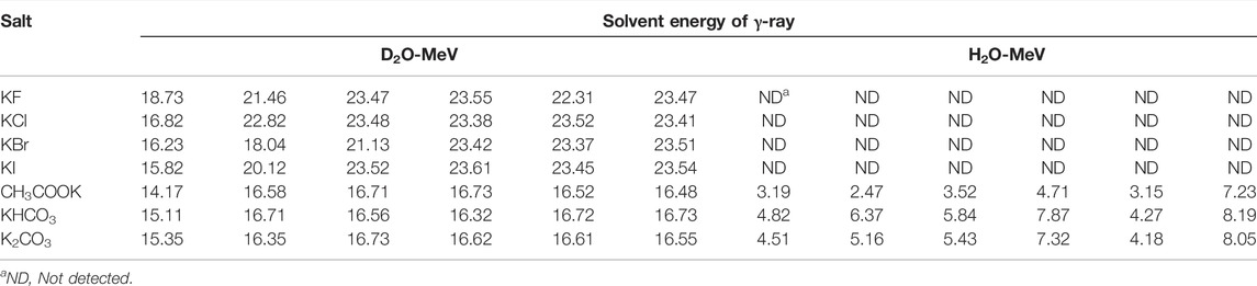
TABLE 3. Discrete Laplace transformation of γ-ray spectrum in both solvents in selected salts.
On the contrary to the solutions of the halide salts, the helium production in the carbon-containing salt solutions cannot be attributed to the D + D reactions solely. Two main reasons for this hypothesis include 1) γ-ray and 4-He productions in light water and 2) the existence of various by-products in liquid and gas phases in both solvents. In 1991, in contrast to the undesirable role of H2O in the low energy nuclear reaction experiments to stop the generation of excess heat (Mills and Kneizys, 1991), the observation of excess heat using an Ni cathode with K2CO3 and H2O as electrolytes without He-4 and gamma-ray detection was reported by Mills and Kneizya (Mills and Kneizys, 1991; Bryan, 1992). Although after publishing their work, a series of attempts were carried out to utilize light water as a solvent in both liquid and gas phases (Patterson, 1994; Patterson, 1996), and not only could they not confirm the generation of the helium gas and gamma rays, but also the role of the used salts was not discussed. But in this work, in addition to verifying the generation of the helium gas and gamma rays, the various by-products in solution and gas phases not only showed that these salts decomposed radically, but also that comparing the gaseous products of the salts containing
The generated products of two or three other conventional pathways of deuteron-deuteron reaction (3-helium, triton, neutron, and proton) were studied. The results showed no evidence to confirm the generation of these products other than acetate solution as the quantity of the above-mentioned products in this solution was not repeatable and reproducible. In Table 2, the maximum temperatures of seven salt solutions after 24 h were tabulated. Due to the extremely low power of the applied wave, and therefore no Joule heating, all generated heat in our work is attributed only to a nuclear fusion reaction. Table 4 shows that increasing the number of micro-shafts causes a reduction in the time to reach the maximum value of temperature. Unfortunately, no correlation was observed between 4-He, γ-ray, and heat in all solutions under our experimental conditions.
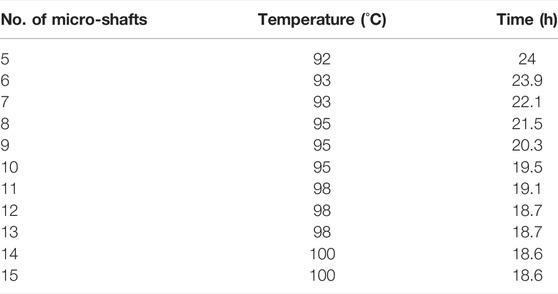
TABLE 4. The variation of required time to reach the maximum temperature vs. the number of micro-shafts in KF solution (1 molL-1).
4 Conclusion
Here we introduced a new method to generate nuclear fusion products in light and heavy waters along with some other products, the most of which are overall water splitting. In the proposed method, a new unique potential, called the TPW, with extremely low potential as a driving force was used to trigger a process on the surface of the micro-shaft in the simple two-micro-shaft system. The first main point of this phenomenon was to create a reaction without any current flowing through the system, that is, the system works under conditions like an open circuit potential system. In this system, concentrated solutions of seven salts, as study cases, were selected among 20 tested solutions. Performing the experiments in light and heavy waters with the same setup conditions showed two different nuclear reactions based on the energy of gamma rays: one was a D + D reaction and the other was a carbon-based reaction. Besides, the overall light and heavy water splitting was also detected as a common reaction in all solutions. To sum up, the results of this work confirm the possibility of the simple production of nuclear fusion products at room temperature. On the other hand, finding the main origin of these events needs further study.
Data Availability Statement
The original contributions presented in the study are included in the article/Supplementary Material, further inquiries can be directed to the corresponding author.
Ethics Statement
This study was admitted and approved by the ethics committee of the Shiraz University Consul
Author Contributions
MD conceived the presented idea. HT-M carried out the analytical method and experiments, wrote the manuscript, discussed the results, and contributed to the final manuscript.
Funding
This study was financially supported by Shiraz University.
Conflict of Interest
The authors declare that the research was conducted in the absence of any commercial or financial relationships that could be construed as a potential conflict of interest.
Publisher’s Note
All claims expressed in this article are solely those of the authors and do not necessarily represent those of their affiliated organizations, or those of the publisher, the editors and the reviewers. Any product that may be evaluated in this article, or claim that may be made by its manufacturer, is not guaranteed or endorsed by the publisher.
Acknowledgments
The authors wish to acknowledge the support received for this work by the Shiraz University Research Council.
Supplementary Material
The Supplementary Material for this article can be found online at: https://www.frontiersin.org/articles/10.3389/fenrg.2022.844516/full#supplementary-material
References
Albagli, D., Ballinger, R., Cammarata, V., Chen, X., Crooks, R. M., Fiore, C., et al. (1990). Measurement and Analysis of Neutron and Gamma-Ray Emission Rates, Other Fusion Products, and Power in Electrochemical Cells Having Pd Cathodes. J. Fusion Energ 9, 133–148. doi:10.1007/bf02627578
Berlinguette, C. P., Chiang, Y.-M., Munday, J. N., Schenkel, T., Fork, D. K., Koningstein, R., et al. (2019). Revisiting the Cold Case of Cold Fusion. Nature 570, 45–51. doi:10.1038/s41586-019-1256-6
Bryan, S. R. (1992). Reply to "Comments on 'Excess Heat Production by the Electrolysis of an Aqueous Potassium Carbonate Electrolyte and the Implications for Cold Fusion'". Fusion Technol. 21, 96. doi:10.13182/fst92-a29713
Fleischmann, M., and Pons, S. (1989). Electrochemically Induced Nuclear Fusion of Deuterium. J. Electroanal. Chem. Interfacial Electrochem. 261, 301–308. doi:10.1016/0022-0728(89)80006-3
Laurence, W. L. (1956). Cold Fusion of Hydrogen Atoms; a Fourth Method Pulling Together. New York Times E7. December 30, 1956.
Mills, R. L., and Kneizys, S. P. (1991). Excess Heat Production by the Electrolysis of an Aqueous Potassium Carbonate Electrolyte and the Implications for Cold Fusion. Fusion Technol. 20, 65–81. doi:10.13182/fst91-a29644
Miskelly, G. M., Heben, M. J., Kumar, A., Penner, R. M., Sailor, M. J., and Lewis, N. S. (1989). Analysis of the Published Calorimetric Evidence for Electrochemical Fusion of Deuterium in Palladium. Science 246, 793–796. doi:10.1126/science.246.4931.793
Patterson, J. A. (1994). Method for Electrolysis of Water to Form Metal Hydride. US Patent # 5,318,675.
Rafelski, J., and Jones, S. E. (1987). Cold Nuclear Fusion. Sci. Am. 257, 84–89. doi:10.1038/scientificamerican0787-84
Salamon, M. H., Wrenn, M. E., Bergeson, H. E., Crawford, H. C., Delaney, W. H., Henderson, C. L., et al. (1990). Limits on the Emission of Neutrons, γ-rays, Electrons and Protons from Pons/Fleischmann Electrolytic Cells. Nature 344, 401–405. doi:10.1038/344401a0
Storms, E. (2007). Science of Low Energy Nuclear Reaction, the: A Comprehensive Compilation of Evidence and Explanations about Cold Fusion. World Scientific, 197–204.
Keywords: gamma ray, nuclear fusion, D + D fusion, 4-He, micro-shaft, heavy water media
Citation: Torabi-Monfared H and Doroodmand MM (2022) Reproducible and Repeatable Generation of 4-He, γ-rays, and Heat in Light and Heavy Waters at Room Temperature. Front. Energy Res. 10:844516. doi: 10.3389/fenrg.2022.844516
Received: 28 December 2021; Accepted: 04 April 2022;
Published: 08 June 2022.
Edited by:
Zhaoming Meng, Harbin Engineering University, ChinaReviewed by:
Guang Hu, Xi’an Jiaotong University, ChinaHuali Wu, University of Wisconsin System, United States
Copyright © 2022 Torabi-Monfared and Doroodmand. This is an open-access article distributed under the terms of the Creative Commons Attribution License (CC BY). The use, distribution or reproduction in other forums is permitted, provided the original author(s) and the copyright owner(s) are credited and that the original publication in this journal is cited, in accordance with accepted academic practice. No use, distribution or reproduction is permitted which does not comply with these terms.
*Correspondence: Mohammad Mahdi Doroodmand, ZG9yb29kbWFuZEBzaGlyYXp1LmFjLmly, ZG9yb29kbWFuZEB5YWhvby5jb20=