 Shan Huang
 Ti Yue
 Pan Yuan
- Science and Technology on Reactor System Design Technology Laboratory, Nuclear Power Institute of China, Chengdu, China
With the continuous improvement of nuclear reactor power, the use of surface microstructures to enhance the heat exchange between the coolant and the solid surface has become the research focus of many researchers. However, the extreme environment inside the core, especially the continuous impact of the high-velocity liquid on the solid surface, poses a severe challenge to the reliable service of the microstructure. To this end, this paper establishes a numerical calculation method for the droplet scouring the solid wall to analyze and evaluate the mechanical feasibility and reliability of the surface microstructure under the impact of high-speed droplets. First of all, the physical process of the liquid droplet scouring the solid surface was described and analyzed, then the mathematical equations which describe the physical process were built by coupling the key physical parameters of the interface such as displacement and stress. Finally, the internal stress distribution and its change trend with and without the microstructure were obtained. The calculation results show that during the process of a droplet hitting the solid surface, due to the superposition of shock waves inside the droplet, there will be a stress field distribution on the solid side that cannot be ignored. The introduction of the surface microstructure will significantly change the stress field distribution on the solid side. The liquid film formed on the surface of the microstructure has a significant buffering effect on the impact of the droplets, which greatly reduces the stress level in the solid. The maximum stress level in the solid with microstructure is only about 50% of that in the solid without the microstructure. Therefore, it can be judged that the surface microstructure can meet the mechanical performance requirements under the condition of droplet scouring.
1 Introduction
With the development of nuclear energy technology, the power of nuclear reactors has also continued to increase. As a result, the heat flux density on the surface of the fuel element has also risen sharply. How to improve the heat transfer efficiency between the surface of the fuel element and the coolant has become an urgent problem for front-line researchers.
Recent studies have shown that surface engineering technology is a means with great potential to enhance heat transfer and increase the value of CHF (Critical Heat Flux). Zhukov’s study demonstrates that the use of a microstructured surface produced by a 3D laser printer leads to a 3.5-fold increase of the heat transfer coefficient in the regimes of bubble boiling and the critical heat fluxes (CHF) on the capillary-porous coating increase with the increasing height of the liquid layer (Zhukov et al., 2020). Wang investigated the boiling heat transfer properties of a copper surface with different microstructures and the effect of size and heat transfer area on heat transfer performance is studied by experiment and simulation. The studies have shown, the surface with microstructure can effectively promote boiling heat transfer and the heat transfer effect of multi-scale T surface is always the best, 1.31 times of single scale surface, 2.38 times of smooth surface (Wang et al., 2021). Tokunaga used a microstructured surface with a wettability gradient to enhance the condensation heat transfer and they fabricated a bi-public microgroove surface with a wettability gradient which could enhance the heat transfer by three times compared with the straight microgroove (Tokunaga and Tsuruta, 2020). Liu found that a straight fin microstructured surface has a higher heat transfer performance of pulsed spray cooling than a smooth surface, but it decreases the surface temperature uniformity. Then mixed surfactants were used to greatly improve the temperature uniformity of the microstructured surface (Liu et al., 2020). Zhu used the microstructure to enhance the heat transfer performance of nitrogen condensation on the vertical plate and the rivulet at the bottom of the micro fin indicates the curved surface structure could change the uniform distribution of the liquid film of the micro fin to accelerate the condensate drainage (Zhu et al., 2021). Shi’s research team has designed the SCGS (supersonic cold gas spray technique) modified surfaces to enhance the downward-facing boiling and the conical pin microstructure shows significant CHF enhancement. The mechanism of CHF enhancement mainly brought by a synergy of Multi-scale structures was also preliminarily analyzed (Shi et al., 2021). In Sun’s research, novel microstructured surfaces were fabricated with spatially-controlled mixed wettability to improve the pool boiling performance and the Synergistic enhancement mechanism was also explored by optimally utilizing the combined effects of mixed wettability and microstructures (Sun et al., 2022). Lei studied the heat transfer performance of block-divided surfaces in the pool boiling heat transfer and all block-divided surfaces show better heat transfer performance than a smooth surface. In his work, MP-3 has the smallest microstructure area but the highest CHF and a modified model to predict the CHFs was proposed (Lei et al., 2020). Park modified outer boiling and inner condensation surfaces of a two-phase heat exchanger tube with electroplated porous microstructures and dip-coated hydrophobic thin film and a significant increase in heat transfer performance of the heat exchanger tube were achieved (Park et al., 2019).
At the same time, the development of advanced manufacturing processes such as 3D printing has made it possible to successfully manufacture some complex surface microstructures. In Kang’s research, microstructures on boiling surfaces were fabricated by 3D microprinting and the boiling heat transfer on surfaces with 3D-printing microstructures was studied (Kang and Wang, 2018). The experimental results showed that the microstructure which generates more nucleation sites can have higher heat flux during the saturated nucleate boiling which is the heat transfer situation in nuclear power plants.
All of these advancements are pushing surface engineering from research to engineering. However, the fuel elements of nuclear reactors have a long-term operation under strong radiation and high temperature and high-pressure water environment, and at the same time, they are subject to water chemical corrosion and fluid erosion. For this reason, the microstructure provided on the surface of the cladding must also have a sufficiently high structural strength to adapt to such a harsh environment. Damage to the surface microstructure will not only cause a reduction in heat exchange efficiency but is also closely related to the safety of nuclear reactors. For this reason, it is necessary to provide support for the selection and demonstration of surface microstructures from the perspective of structural mechanics.
However, at present, apart from experimental methods, there are no particularly effective methods to quickly analyze the mechanical feasibility of microstructures. To better analyze and verify the feasibility of surface microstructures in nuclear reactors, especially the mechanical stability under high-velocity scouring environments. This paper analyzes the physical process of the surface microstructure being washed by high-speed fluid and establishes a mathematical model on this basis. Then, the velocity transmission is used to couple the governing equations of the liquid with the governing equations of the solid, and the entire calculation area is solved by the discrete iterative method to obtain the stress distribution inside the surface microstructure. By comparing and analyzing the internal stress distribution law of different microstructure sizes during high-speed fluid scouring, it provides suggestions and ideas for improving the mechanical stability of the surface microstructure.
2 Physical Process Description
Obtaining the real-time stress distribution inside the microstructure under the condition of high-speed fluid scouring is the key to this article. To calculate and analyze this process, we need to sort out the physical process of the impact of high-speed fluid on the surface microstructure. To facilitate the subsequent calculation and analysis, we need to define a specific microstructure form. Our research team has designed and processed a variety of surface microstructures. We will select a typical one as the object of subsequent analysis, that is the jagged microstructure, as shown in Figure 1.
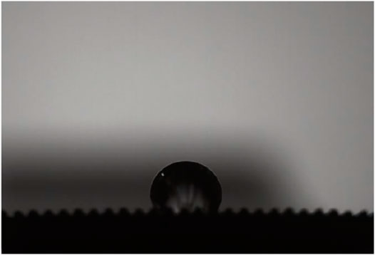
FIGURE 1. The jagged microstructure in surface wettability experiment.
After analysis, it is found that the process of fluid scouring the surface microstructure at high speed is a process in which countless liquid droplets hit the microstructure at a high speed. Although the droplet hits the microstructure in many directions, it can be known by Newton’s second law: when the direction of the droplet’s motion is perpendicular to the plane where the microstructure is located, the microstructure will receive the greatest impact, and the stress level of the microstructure will be the largest at this time. This is also the working condition that we should consider.
After clarifying the specific form of the microstructure, a simplified physical process model can be obtained, as shown in Figure 2. The circle in the figure represents the liquid drop, the green part represents the solid part, and the continuous triangle represents the jagged microstructure. The angle between the droplet and the solid is called the contact angle, and this angle is also constant as the impact process progresses. When a droplet hits a solid page at a relatively fast speed, a shock wave will be generated inside the droplet due to the deformation and compression of the droplet. The shock wave is generated on the liquid-solid contact surface and starts to propagate inside the droplet. The place where the shock wavefront passes is called the high-density zone (disturbed area). The shock wave generated by the liquid-solid impact process will cause a pressure distribution within the droplet that varies with space and time. According to the principle of force and reaction force, the pressure change of the droplet will cause the corresponding stress wave to propagate inside the solid, so the inside of the solid will also produce a corresponding stress distribution that changes with space and time.
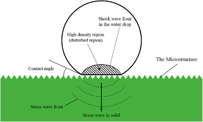
FIGURE 2. The schematic of the liquid-solid impact process.
Compared with the smooth surface of the solid, the microstructure may change the stress distribution on the solid side. If there is a large stress distribution inside or near the microstructure, it may cause the microstructure to fall off and break. In our study, the maximum stress in the solid is our focus and it has been proved that the internal pressure of the droplet will have a maximum value before the lateral jet forms in the liquid drop (Heymann, 1969; Field, 1999), so we only pay attention to the process before the broke of the liquid droplet. So, the shape and volume change of the droplet can be negligible during this period. Therefore, the focus of our research is to get the stress distribution in the microstructure before the droplet breaks and compare the changes in the stress field on the solid side with and without the microstructure.
3 Governing Equation
This phenomenon of droplets hitting and scouring solid surfaces at high speed not only in the nuclear reactor but also exists in other industries, like the turbine in the coal power plant and the propeller of the ship, and the base solid may be broken by the continuous water drops with relatively high velocity (Lee, 2002). A significant transient stresses distribution can be produced by the high-speed, micron-sized water droplets where the liquid impacts the solid. And in Denis’s research, these impaction jets can travel at up to 40 times the velocity of the impact (Bartolo et al., 2006). Because of the small volume and high flow velocity of liquid droplets, the stress distribution in the solid can’t be measured easily by the experiment. Therefore, it is necessary to establish a numerical model to obtain the stress.
At first, the classical model of the impact between a liquid flow and solid was built by Cook, and the numerical model was set to be solved under one dimensional (Cook, 1928). Then, a hydrodynamic analysis review of the cylinder under impact was presented by Cointe (Cointe and Armand, 1987). Many researchers’ assumptions and results, such as Wagner (Wagner, 1932), were discussed and analyzed. Then, in 1992 and 1994, Korobkin investigated the impact process of the blunt-body between two completely different liquid surfaces, and the pressure and the velocity inside the liquid computed region were obtained (Korobkin, 1992; Korobkin, 1994).
With the quick development of high-speed photography, there were more experimental researches on the impact process between liquid and solid. But, most of them are focused on the pressure distribution on the liquid side. In 2003, Kim set up an experimental system, and the process of a droplet with high-velocity impacts on a solid surface was imaged (Kim et al., 2003). However, there is little research focus on the calculation of stress distribution in the solid. In 2008, Li and Zhou built a numerical model which considers the compressibility of liquid (Li et al., 2008), and the stress in the solid was finally obtained in the liquid-solid impact process (Zhou et al., 2008). In 2016, Semenov and Wu also got the hydrodynamic force caused by the impact when they investigated the impact process of a free surface flow and a permeable solid (Semenov and Wu, 2016). From 2010, Xiong has been focused on the numerical analysis of liquid-solid impingement by the method of moving particle semi-implicit. And their impact pressure in the liquid obtained by the numerically calculation has a very good agreement with the Heymann correlation and lateral jet which would cause a big shear stress has also been proved (Xiong et al., 2010). Their research team also carried an investigation on the mitigation effect of the water film in the liquid droplet impingement onto a wet rigid wall, and the results of which will provide obvious support for our calculation results analysis (Xiong et al., 2011). And Xiong also proposed a new correlation for the pressure load caused by the sodium impingement, which was in good consistent with the simulation results (Xiong et al., 2012). But all the research above has not taken the effect of microstructure into consideration.
In this paper, we use the 2-D wave equations developed from Li’s work (Li et al., 2008) to describe the liquid-solid impact process and the governing equations which couple the liquid and solid can be got as follows:
In our research, the physical process was treated as an asymmetrical process because of the symmetry of the spherical droplet. And the coupling between the liquid and solid was done by the connection of the solid particle displacement and the liquid particle velocity on the interface. Through the equations and settings above, the solid particles displacement can be obtained, and then we can get the stress and strain by the equations below:
Then, the 4th strength theory was used to convert all these different components of stress in the solid side into equivalent stress:
and define the dimensionless equivalent stress:
The denominator in the formula represents the magnitude of the water hammer force (Lee, 2002), which mainly considers the density and velocity of the droplets. Unless otherwise specified, the stress mentioned later is dimensionless equivalent stress。
In this paper, the finite difference method (Le Bot et al., 2015; Peng and Cao, 2016) is used to solve the liquid-solid interaction problems. And we use the 2th-order accuracy backward difference scheme for the discretization of the time-derivative term:
And for the space-derivative terms,
At last, TDMA which stands for the tridiagonal matrix algorithm was used to solve the discretized equations, and the Guass-Sidel iteration method was also employed. The key part of this calculation process is to set the pressure of the liquid particle on the boundary as the boundary condition of the solid side calculation to get the velocity. Like the discretize way above, the Lame equation can also be discretized. And, the flow diagram of the liquid-solid impact calculation can be expressed as in Figure 3.
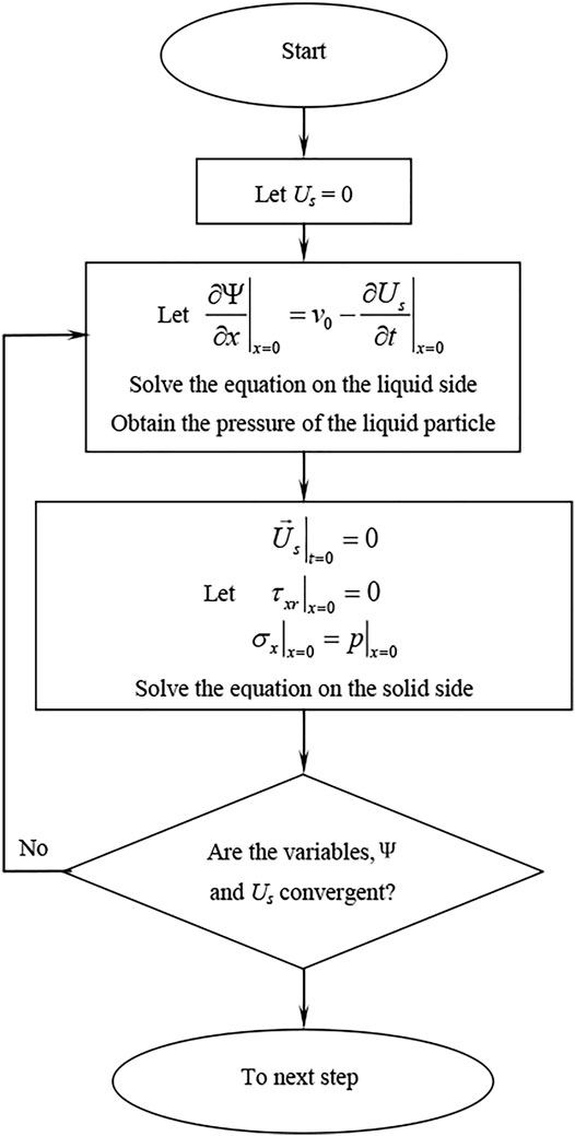
FIGURE 3. The flow diagram of the liquid-solid impact calculation.
4 Calculation Results Analysis
4.1 Without Microstructure
According to the previous control equations and solution settings, we have carried out the relevant calculations. To compare the stress of the microstructure more intuitively, we first calculated the process of the droplet impacting the smooth wall (when there is no microstructure).
Table 1 gives the physical properties of solids and water. In the calculation, the initial diameter of the water drop was set to be 1 mm and the impact velocity was set to 50 m/s.
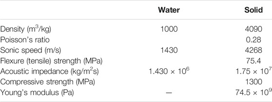
TABLE 1. the physical properties involved in the calculation.
Figure 4 shows stress calculation results in the solid when time is ranging from 10 to 60 ns before the broke of the liquid droplet. And white lines were used to stand for the structure shapes, the horizontal line stands for the surface of the impacted solid while the arc line stands for the shape of the liquid droplet.
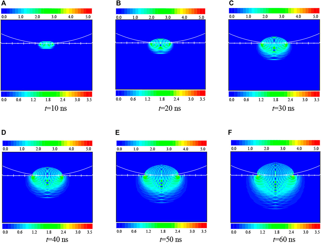
FIGURE 4. The transient stress distribution in the solid. (A) t = 10 ns, (B) t = 20 ns, (C) t = 30 ns, (D) t = 40 ns, (E) t = 50 ns, (F) t = 60 ns.
The impact of the water droplet causes a coronal disturbed zone in the liquid and the shock front inside the droplet forms. The density and modulus of the disturbed liquid are higher than the normal liquid, and thanks to that the propagation speed of the sound wave in the disturbed zone is much higher than that in the undisturbed zone. The difference in the propagation speed would result in wave superposition. While the propagation speed of the wave in the solid side would be influenced less, so the stress distribution in the solid side mainly takes over a spherical zone.
We also analyzed the energy conversion in the liquid-solid impact process, including the relationship among the total energy, the energy in the liquid and the energy in the solid. The computation results are shown in see Figure 5. And we can see that the total energy remains constant and it does not change with the time, and this phenomenon is well explained by the law of energy conservation. For the total kinetic energy in the liquid side, it has a small decrease at the end which indicates some liquid kinetic energy transforms into other energy. In our research, the impact velocity is relatively high and the total deformation of the liquid droplet is very small, about 0.3%. So, the decrease of liquid kinetic energy is on the same order which is good agreement with this number.
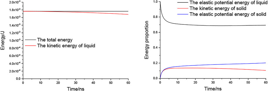
FIGURE 5. The energy conversion process of the impact process.
The lost kinetic energy of liquid has turned into other energy forms, including the elastic potential energy of liquid, the kinetic energy of solid and the elastic potential energy of solid. And because of the difference of the elastic modulus between the liquid and solid, the liquid gets a more obvious deformation than the solid, the elastic potential energy of liquid is much higher than the elastic potential energy of solid. Although the energy has transferred from the liquid to the solid, the elastic potential energy of liquid is still much higher than the elastic potential energy of solid. And the kinetic energy of solid is also restricted to a low level due to the restriction of the solid particles’ displacement. As we can conclude, the lost kinetic energy of liquid has most turns into the elastic potential energy of liquid, only a small part of them results in the energy stored in the solid.
4.2 With Microstructure
Then, we calculated the situation with microstructures. The transient stress distribution in the solid with equilateral triangle microstructure, which has a 25 μm apex height, was shown in Figure 6. Comparing the calculation results before and after the introduction of the microstructure, it is obvious that the existence of the microstructure can change the stress distribution inside the solid greatly: the stress level of the base solid has dropped significantly, and the original stress concentration point in the base solid is no longer exist; the stress level of the microstructure on the surface is roughly the same as that of the base solid, but there seems to be a certain degree of stress concentration in the liquid film on the outside of the microstructure.
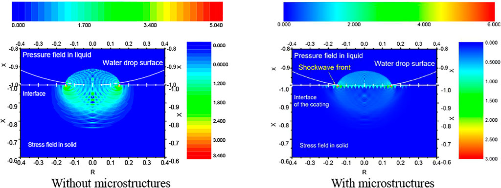
FIGURE 6. The transient stress distribution in the solid (t = 50 ns).
Figure 7 shows an enlarged view of the stress distribution in the solid. The existence of the microstructure makes a liquid film form which exists on the interactive surface, and the liquid film not only fills the gaps of the microstructures but there may also be a certain thickness of the liquid film layer in the space above the microstructure. This liquid film has a buffering effect on the impact process, so the stress level inside the base solid and the microstructure are not high.
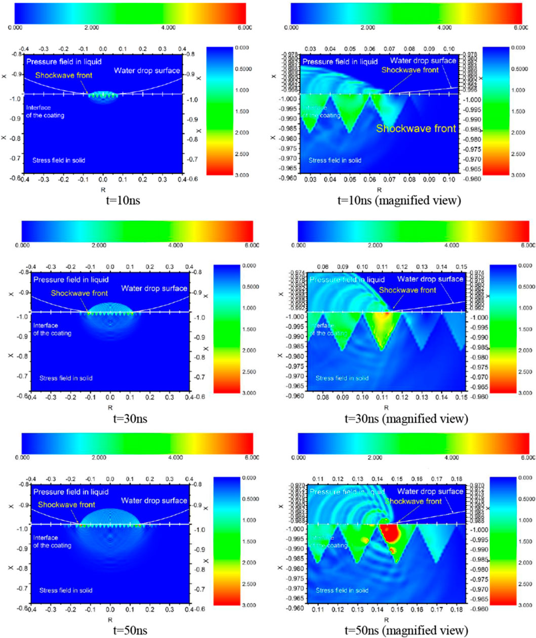
FIGURE 7. The transient stress distribution in the solid.
The liquid stored in the microstructure is the main reason for buffering. At the same time, the liquid between the microstructure gaps also bears the greatest stress distribution. Although there will be a large pressure concentration in this part of the liquid, the stress level of the pressure concentrated feedback to the solid or microstructure is not high.
4.3 Quantitative Analysis
The tendency of the maximum equivalent stress was shown in Figure 8. The maximum equivalent stress in solid with or without the microstructure. When there is no microstructure, the maximum internal stress in the base solid increases with the impact progressing, and the overall trend is that the oscillation increases linearly. The maximum stress change trend with the microstructure is shown by the blue line in the figure. It can be seen that the stress level inside the base material is extremely low at the beginning of the impact. Due to the influence of stress concentration inside the liquid film in the later stage, the maximum stress inside the microstructure also rises. Although the maximum stress inside the microstructure increased significantly in the later period, and the rate of increase was also faster. But in general, the maximum stress level inside the solid after the introduction of microstructures is only 50% of that without microstructures.
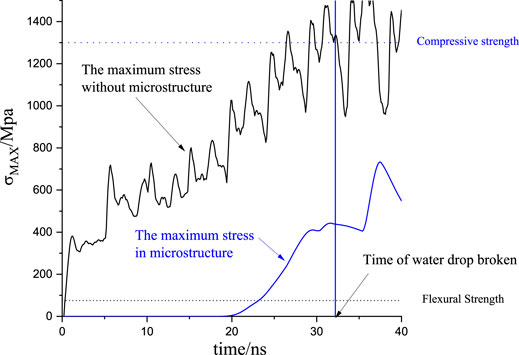
FIGURE 8. The tendency of the maximum equivalent stress.
5 Conclusion
In this paper, the mechanical feasibility of applying the surface microstructure to improve the heat transfer efficiency in nuclear reactor is evaluated by establishing a numerical model of the liquid-solid impact process. First, the physical process of the liquid droplet scouring the solid surface was described, then the liquid-solid impact mathematical governing equation coupling the two phases was obtained by passing the pressure of liquid and displacement of solid on the interface. Through this calculation, the stress distribution in the solid and microstructure was analyzed and compared. The main results and conclusions obtained are as follows:
(1) When the droplet impacts continuously on the solid surface, due to the superposition of the shock waves inside the liquid, the kinetic energy lost by the droplets is finally converted into the elastic potential energy of the liquid, the kinetic energy of the solid and elastic potential energy of the solid, so a stress field distribution which cannot be ignored exists inside the solid.
(2) The surface microstructure can significantly change the distribution of the stress field inside the solid. The hydrophobic effect of the microstructure makes some liquid of the droplet form a liquid film in and above the microstructure. The buffering effect of the liquid film can greatly reduce the stress level in the solid. Although a certain degree of stress concentration in the liquid film causes the increase of the stress inside the microstructure, the maximum stress level inside the microstructure is only about 50% of that in the base solid without the microstructure.
The results in this paper show that the surface microstructure can not only meet the mechanical performance requirements under the condition of droplet impacting but also reduce the stress level inside the entire solid. Once again, the microstructure was proved to be with great potential in the heat transfer enhancement considering the perspective of mechanical feasibility.
Data Availability Statement
The original contributions presented in the study are included in the article/Supplementary Material, further inquiries can be directed to the corresponding author.
Author Contributions
SH: the physical model and numerical governing equations. TY, PY, and FZ: data processing. HW: writing-editing. ML and CH: project administration. HL and YL: funding.
Funding
This work was supported by National Key R&D Program of China (Grant No. 2018YFE0116100) and Natural Science Foundation of China (Grant No. 12105273).
Conflict of Interest
The authors declare that the research was conducted in the absence of any commercial or financial relationships that could be construed as a potential conflict of interest.
Publisher’s Note
All claims expressed in this article are solely those of the authors and do not necessarily represent those of their affiliated organizations, or those of the publisher, the editors and the reviewers. Any product that may be evaluated in this article, or claim that may be made by its manufacturer, is not guaranteed or endorsed by the publisher.
References
Bartolo, D., Josserand, C., and Bonn, D. (2006). Singular Jets and Bubbles in Drop Impact. Phys. Rev. Lett. 96, 124501. doi:10.1103/physrevlett.96.124501
Cointe, R., and Armand, J.-L. (1987). Hydrodynamic Impact Analysis of a Cylinder. J. Offshore Mech. Arctic Eng. 109, 237–243. doi:10.1115/1.3257015
Cook, S. S. (1928). Erosion by Water-Hammer. Proc. R. Soc. Lond. Ser. A Contain. Pap. a Math. Phys. Character 119, 481–488.
Field, J. E. (1999). ELSI Conference: Invited Lecture. Wear 233-235, 1–12. doi:10.1016/s0043-1648(99)00189-1
Heymann, F. J. (1969). High‐Speed Impact between a Liquid Drop and a Solid Surface. J. Appl. Phys. 40, 5113–5122. doi:10.1063/1.1657361
Kang, Z., and Wang, L. (2018). Boiling Heat Transfer on Surfaces with 3D-Printing Microstructures. Exp. Therm. Fluid Sci. 93, 165–170. doi:10.1016/j.expthermflusci.2017.12.021
Kim, H.-Y., Park, S.-Y., and Min, K. (2003). Imaging the High-Speed Impact of Microdrop on Solid Surface. Rev. Scientific Instr. 74, 4930–4937. doi:10.1063/1.1614860
Korobkin, A. (1992). Blunt-body Impact on a Compressible Liquid Surface. J. Fluid Mech. 244, 437–453. doi:10.1017/s0022112092003136
Korobkin, A. (1994). Blunt-body Impact on the Free Surface of a Compressible Liquid. J. Fluid Mech. 263, 319–342. doi:10.1017/s0022112094004131
Le Bot, C., Vincent, S., Meillot, E., Sarret, F., Caltagirone, J.-P., and Bianchi, L. (2015). Numerical Simulation of Several Impacting Ceramic Droplets with Liquid/solid Phase Change. Surf. Coat. Techn. 268, 272–277. doi:10.1016/j.surfcoat.2014.10.047
Lee, M.-K., Kim, W.-W., Rhee, C.-K., and Lee, W.-J. (2002). An Analysis of Stress Waves in 12Cr Steel, Stellite 6B and TiN by Liquid Impact Loading. Nucl. Eng. Des. 214, 183–193. doi:10.1016/s0029-5493(02)00053-5
Lei, Z., Liu, B., Xu, P., Zhang, Y., and Wei, J. (2020). The Pool Boiling Heat Transfer and Critical Vapor Column Coalescence Mechanism of Block-Divided Microstructured Surfaces. Int. J. Heat Mass Transfer 150, 119362. doi:10.1016/j.ijheatmasstransfer.2020.119362
Li, N., Zhou, Q., Chen, X., Xu, T., Hui, S., and Zhang, D. (2008). Liquid Drop Impact on Solid Surface with Application to Water Drop Erosion on Turbine Blades, Part I: Nonlinear Wave Model and Solution of One-Dimensional Impact. Int. J. Mech. Sci. 50, 1526–1542. doi:10.1016/j.ijmecsci.2008.08.001
Liu, N., Yu, Z., Zhu, T., Yin, X., and Zhang, H. (2020). Effects of Microstructured Surface and Mixed Surfactants on the Heat Transfer Performance of Pulsed spray Cooling. Int. J. Therm. Sci. 158, 106530. doi:10.1016/j.ijthermalsci.2020.106530
Park, Y., Park, H.-K., Pusey, A., Hong, J., Park, J., Chung, B.-J., et al. (2019). Heat Transfer Augmentation in Two-phase Flow Heat Exchanger Using Porous Microstructures and a Hydrophobic Coating. Appl. Therm. Eng. 153, 433–447. doi:10.1016/j.applthermaleng.2019.03.030
Peng, W., and Cao, X. (2016). Numerical Simulation of Solid Particle Erosion in Pipe Bends for Liquid-Solid Flow. Powder Techn. 294, 266–279. doi:10.1016/j.powtec.2016.02.030
Semenov, Y. A., and Wu, G. X. (2016). Liquid Impact on a Permeable Solid Body. Eur. J. Mech. B Fluids 57, 22–30. doi:10.1016/j.euromechflu.2016.02.004
Shi, H., Li, S., Zhong, D., Meng, J. a., Luo, X., Zhang, X., et al. (2021). CHF Enhancement of Downward-Facing Saturated Pool Boiling on the SCGS-Modified Surfaces with Multi-Scale Conical Pin Fin Structures. Int. J. Heat Mass Transfer 181, 121848. doi:10.1016/j.ijheatmasstransfer.2021.121848
Sun, X. Z., Li, Q., Li, W. X., Wen, Z. X., and Liu, B. (2022). Enhanced Pool Boiling on Microstructured Surfaces with Spatially-Controlled Mixed Wettability. Int. J. Heat Mass Transfer 183, 122164. doi:10.1016/j.ijheatmasstransfer.2021.122164
Tokunaga, A., and Tsuruta, T. (2020). Enhancement of Condensation Heat Transfer on a Microstructured Surface with Wettability Gradient. Int. J. Heat Mass Transfer 156, 119839. doi:10.1016/j.ijheatmasstransfer.2020.119839
Wagner, H. (1932). Über Stoß- und Gleitvorgänge an der Oberfläche von Flüssigkeiten. Z. Angew. Math. Mech. 12, 193–215. doi:10.1002/zamm.19320120402
Wang, L., Wang, Y., Cheng, W., Yu, H., and Xu, J. (2021). Boiling Heat Transfer Properties of Copper Surface with Different Microstructures. Mater. Chem. Phys. 267, 124589. doi:10.1016/j.matchemphys.2021.124589
Xiong, J., Koshizuka, S., and Sakai, M. (2010). Numerical Analysis of Droplet Impingement Using the Moving Particle Semi-implicit Method. J. Nucl. Sci. Technol. 47, 314–321. doi:10.1080/18811248.2010.9711960
Xiong, J., Koshizuka, S., and Sakai, M. (2011). Investigation of Droplet Impingement onto Wet Walls Based on Simulation Using Particle Method. J. Nucl. Sci. Techn. 48, 145–153. doi:10.1080/18811248.2011.9711689
Xiong, J., Koshizuka, S., Sakai, M., and Ohshima, H. (2012). Investigation on Droplet Impingement Erosion during Steam Generator Tube Failure Accident. Nucl. Eng. Des. 249, 132–139. doi:10.1016/j.nucengdes.2011.08.048
Zhou, Q., Li, N., Chen, X., Xu, T., Hui, S., and Zhang, D. (2008). Liquid Drop Impact on Solid Surface with Application to Water Drop Erosion on Turbine Blades, Part II: Axisymmetric Solution and Erosion Analysis. Int. J. Mech. Sci. 50, 1543–1558. doi:10.1016/j.ijmecsci.2008.08.002
Zhu, S., Zhi, X., Gu, C., Wang, K., and Qiu, L. (2021). Enhancing Heat Transfer Performance of Nitrogen Condensation on Vertical Plate with Microstructure. Int. J. Heat Mass Transfer 172, 121219. doi:10.1016/j.ijheatmasstransfer.2021.121219
Zhukov, V. I., Pavlenko, A. N., and Shvetsov, D. A. (2020). The Effect of Pressure on Heat Transfer at Evaporation/boiling in Horizontal Liquid Layers of Various Heights on a Microstructured Surface Produced by 3D Laser Printing. Int. J. Heat Mass Transfer 163, 120488. doi:10.1016/j.ijheatmasstransfer.2020.120488
Keywords: microstructure, liquid-solid impact, numerical simulation, impact stress, feasibility
Citation: Huang S, Yue T, Yuan P, Zhu F, Wang H, Liu M, Huang C, Li H and Li Y (2022) Mechanical Feasibility Analysis of the Surface Microstructure to Be Used in the Nuclear Reactor. Front. Energy Res. 10:843212. doi: 10.3389/fenrg.2022.843212
Received: 25 December 2021; Accepted: 17 February 2022;
Published: 23 March 2022.
Edited by:
Haomin Yuan, Argonne National Laboratory (DOE), United StatesReviewed by:
Jinbiao Xiong, Shanghai Jiao Tong University, ChinaLuteng Zhang, Chongqing University, China
Copyright © 2022 Huang, Yue, Yuan, Zhu, Wang, Liu, Huang, Li and Li. This is an open-access article distributed under the terms of the Creative Commons Attribution License (CC BY). The use, distribution or reproduction in other forums is permitted, provided the original author(s) and the copyright owner(s) are credited and that the original publication in this journal is cited, in accordance with accepted academic practice. No use, distribution or reproduction is permitted which does not comply with these terms.
*Correspondence: Shan Huang, MTg2OTE2MzU3MTNAMTYzLmNvbQ==