 Qian Sun
 Yu Ji
Yu Ji Jun Sun
94% of researchers rate our articles as excellent or good
Learn more about the work of our research integrity team to safeguard the quality of each article we publish.
Find out more
ORIGINAL RESEARCH article
Front. Energy Res., 27 April 2022
Sec. Nuclear Energy
Volume 10 - 2022 | https://doi.org/10.3389/fenrg.2022.841631
This article is part of the Research TopicNumerical Methods and Computational Sciences Applied to Nuclear EnergyView all 12 articles
Simulations of radiation heat transfer in fuel rod bundles are necessary for the thermal hydraulic design and safety analysis of open lattice gas-cooled reactors, which always operate at high temperatures. To save the computational costs, existing radiation models in system codes such as RELAP5 commonly assume each fuel rod to own the uniform radiosity over the rod surface. Previous research studies have indicated that the uniform radiosity assumption could overestimate the heat transfer flux and under-predict the maximum fuel rod temperature, and the anisotropic correction was tried by dealing with non-uniform reflected radiation. To better model the non-uniform radiosity effect, the Gehart’s method based on the non-uniform absorbed radiation is introduced in this study. By dividing the surface of each rod into six segments, the one-sixth rod view factors are derived in specific rod and near wall sections to generate the segment-to-segment absorption factors. By summarizing those segment-to-segment absorption factors, the rod-to-rod and rod-to-wall absorption factors are modified and implemented into RELAP5 to improve the radiation heat transfer model. The two-dimension radiation heat transfer problem in the nuclear fuel rod bundle is simulated in FLUENT as the benchmark and in RELAP5 for comparison. Fuel rod bundles in hexagonal arrays were investigated with various surface emissivity and pitch-to-diameter ratios (p/d). The simulations indicated that the method of rod segment division and absorption factor modification could reflect the non-uniform radiosity, and the results were related to the values of p/d and surface emissivity. The modified radiation heat transfer model in RELAP5 validated that the deviations of the maximum temperature were reduced from around 20% to 1%,3%,8% for p/d = 1.1, 1.2, and 1.3, respectively. Rod bundles with larger p/d required more radiative rods in the analyses of absorption factor modifications. The present radiation heat transfer model should be studied and tested in three-dimension cases to further prove that it is appropriate for the nuclear rod bundles.
Human beings have always maintained a strong curiosity about deep space exploration. For deep space exploration, an efficient and reliable space power is critically important. Among all realizable technologies, the space nuclear reactor power shows a superior performance compared to chemical energy battery, solar battery, and radioisotope nuclear power due to its long-term maintenance at a high power level in complex space environment. As the power level requirement of space facilities increases rapidly, the gas-cooled reactor combined with the closed Brayton cycle provides the most promising energy conversion pathway for megawatt applications (Stanculescu, 2005; Zika and Wollman, 2006; Tournier et al., 2006; El-Genk and Tounier, 2008). Both the United States and Russia have developed megawatt-class, gas-cooled space reactor concepts. In 2003, NASA started the Prometheus project (Zika and Wollman, 2006) which adopts a helium xenon mixture cooled reactor with a thermal power rating of 1 MW. The fuel is mainly UO2 or UN. The design outlet temperature of the reactor is about 1150K. Several core configurations have been investigated, including the open lattice, pin in block, and monoblock, as shown in Figure 1. The Prometheus Project Reactor Module Final Report (Zika and Wollman, 2006) points out that the open lattice design provides the lowest mass, which is a huge advantage for space missions. Russia announced its new space nuclear project with thermal power up to 3.5 MW (Dragunov, 2015). It is also cooled by helium xenon mixture and adopts traditional UO2 as the fuel. The designed reactor outlet temperature was 1500K. However, other details are not available. Recently, the open lattice core design has attracted considerable interest as it can greatly reduce the system mass (Meng et al., 2019; Qin et al., 2020).
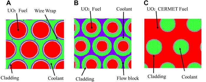
FIGURE 1. Core arrangement options [Ashcroft, J., and C. Eshelman. 2006]. (A) Open lattice, (B) Pin in block, (C) Monoblack.
In the open lattice core, the coolant channel is the gap between hundreds of fuel rods. Normally, the outlet temperature of the coolant in these gas-cooled reactors should be raised to 1,100–1,500 K to ensure an acceptable thermal-to-electricity conversion efficiency and the temperature on the surface of the fuel rods could be extremely high (Ashcroft and Eshelman, 2006; Dragunova, 2021). Hence, thermal radiation in fuel rod bundles plays a vital role in the heat transfer processes inside the core. In addition, under certain postulated accident scenarios such as loss of coolant, the only way of heat rejection is the radiation heat transfer from the fuel rod bundles to the pressure vessel and, finally, to the space. Therefore, the study of radiation heat transfer between rod bundles is of the determinate essence for the thermal design and safety analysis of the open-lattice reactor.
To investigate the radiation heat transfer between rod bundles, the Computational Fluid Dynamics (CFD) methods can provide detailed and accurate simulation results, but for the open-lattice core, it is extremely time-consuming and inefficient because of the complex geometry. Traditionally, the system codes including ICARE, MELCOR, and RELAP5 are adopted for the transient and accident analysis of the nuclear system. These codes are all based on a network of 1-D or 0-D volumes and some assumptions and approximations have to be employed to ensure an acceptable computational speed. Therefore, when using the system code to study the radiative heat exchange in an open-lattice core, it is very important to establish a reasonable radiation heat transfer model for rod bundles to balance the accuracy and cost.
Existing radiation models implemented in codes such as ICARE, MELCOR, and RELAP5 are based on the net radiation method. The net radiation method assumes each radiation surface has a uniform radiosity, viz., a uniform radiation leaving the surface, and the radiosity exchange is accounted for by a “view factor,” which is related to the size, separation distance, and orientation of involved surfaces. When using the net radiation method to model the radiation heat transfer of rod bundles in the reactor, a fuel rod surface is usually treated as a single unit with uniform circumferential radiosity (sum up of self-emitted radiation and reflected part of the incident radiation). However, the uniform radiosity assumption is usually not realized for the rod surface in reactor core. When there is a temperature gradient around a fuel rod, as shown in Figure 2, the temperature of rod No. 1 is higher than that of rod No. 3, and then the incident radiation on the left part of rod No. 2 from rod No. 1 is greater than the right part from rod No. 3. Consequently, the reflected radiation of rod No. 2 would be non-uniform since most of the incident radiation returns along the original direction as seen in Figure 2A. Meanwhile, if the uniform radiosity assumption is adopted, the projected radiation from rod No. 1 to rod No. 2 will be reflected isotopically around the circumference; thus, part of it will reach to rod No. 3, as shown in Figure 2B. The uniform model virtually enhances the radiation heat transfer between rod No. 1 and rod No. 3, because of a “penetration” through rod No. 2 to rod No. 3, thus leading to an overestimated effect between different surfaces of the system (Naitoh et al.,1977; Watson, 1963; Cox, 1977).
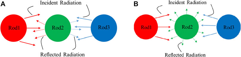
FIGURE 2. Radiosity amoung rod bundles. (A) Non-uniform radiosity. (B) Uniform radiosity.
To compensate the overestimation of the radiation heat transfer rate between rod bundles, anisotropic correction was proposed by Andersen and Tien (1979) to account for the non-uniform reflected radiation. Subsequently, the correction was further improved by Tien et al. (1979) and was implemented in the safety analysis code SCDAP. However, little has been done to investigate the effect of anisotropic correction (Sohal, 1986). Clearly, multiple units performed in the circumferential direction of each fuel rod would reduce the non-uniform radiosity error. Naitoh et al. (1977) suggested for the square rod bundle that it is necessary to divide at least 4 units. Rector (1987) developed the software RANGEN for calculating the view factors between rod bundles in which a rod on a square pitch is divided into 4 parts, and a rod on a triangular pitch is divided into 6 parts. More subdivision of each rod surface would improve the prediction. However, this will greatly increase the computational cost for large arrays of rods.
The uniform radiosity assumption substantially arises from the use of view factors in the net radiation method. Meanwhile, another method for analyzing radiation heat transfer between surfaces, Gebhart’s method (Gebhart, 1959, 1971), which is based on the absorption factors, does not require a uniform radiosity assumption, but needs an accurate absorption factors matrix. Compared with the view factor, which is purely geometrical, the absorption factors are a combination of geometry and surface emissivities. Hence, absorption factors totally characterize radiation heat transfer. The absorption factors can be obtained by matrix transformation from the view factors. It can also be gained through the ray tracing method or Monte Carlo method.
Klepper (1963) first used the ray tracing method to obtain the radiation absorption factors between rod bundles arranged in squares and equilateral triangles. His research results were adopted by Cox (1977), who abandoned his rod-to-rod view factors and improved the agreement between the predicted temperature results with the profiles that were experimentally measured. However, Klepper did not discuss the absorption factors around the wall region. Manteufel (1991) used the Monte Carlo method to calculate the view factors on the basis of more finely divided surface areas for each rod and then applied the matrix-inversion technology to calculate the rod-to-rod and rod-to-wall absorption factors and produced much more accurate results. Meanwhile, the Monte Carlo calculation step in Manteufel, D’s procedure increased the computational cost.
Based on the previous research studies, it can be seen that the assumption of uniform radiosity around the circumference of the fuel rod is not met in practice, and it is recommended that the radiation heat transfer equations be solved using Gebhart’s method with the accurate absorption factors. However, to get the absorption factors, the ray tracing method or Monte Carlo method is time consuming. Thus, in this study, the absorption factors derived from the one-sixth rod for compact fuel rod bundles is introduced, and Gebhart’s method is implemented in RELAP5 to improve the radiation heat transfer model for rod bundles. The article is organized as follows. Theory of radiation exchange between the surfaces is introduced in Section 2. The construction of absorption matrices developed in this study is provided in Section 3. The radiation heat transfer simulations in enclosed hexagonal rod arrays are shown in Section 4. The conclusion and future work are given in Section 5.
In this section, both the net radiation method and Gebhart’s method will be introduced.
Almost all the engineering radiation heat transfer calculations are based on the net radiation or radiosity method.
For the surface i, the radiosity Ri refers to the total radiant energy leaving a unit surface in a unit time:
The radiosity Ri not only includes the surface self-radiation
The energy incident on surface i for an enclosure containing n surfaces is as follows:
where Ai is the area of surface i, incident radiation Ji refers to the total radiant energy input to a unit surface in a unit time, and Fj,i is the view factor, which represents the proportion of radiant energy leaving from surface j to arrive at surface i. With the interchangeability of view factor
Therefore,
Elimination of Ji from Eqn. 1 by using Eqn. 4 gives the following:
The net radiant heat flux of surface i can be expressed as follows:
Combining Eqs 5, 6, the following equation is obtained:
Eqn. 5 are the general equations for determining radiation exchange in a gray, diffuse enclosure of n surfaces by using the net radiation method. After solving the effective radiation R of each surface, the net radiant heat flux of each surface can be obtained according to Eqn. 7.
For analyzing the radiation heat transfer between surfaces, Gebhart introduced the concept of absorption factor Gi,j, which represents the fraction of the energy finally absorbed by the surface j from the emission of surface i, including reflections by other surfaces.
For surface i in an enclosure containing n surfaces, the radiation heat transfer equation can be expressed as follows:
where
Similar to the view factor, the absorption factor has reciprocity and conservation properties. For two surfaces i and j, the energy rate radiated from i to j is
For a closed system, all radiation emitted from any surface must fall on surfaces of the system.
Thus
Because of
The net radiant heat flux of surface i can be expressed as follows:
It can be seen from Eqn. 12 that the key issue of Gebhart’s method to solve the radiation heat transfer is to obtain the absorption factors.
The concept of absorption factor and view factor are similar, but their meanings are different.
The view factor Fi,j represents the proportion of the radiant energy leaving the surface i directly reaching the surface j, regardless of the reflection through other surfaces.
The absorption factor Gi,j represents the portion of the radiant energy emitted from the surface i that is finally absorbed by the surface j, including multiple reflections through other surfaces.
The theoretical derivation of the view factor is introduced in many literatures or textbooks, but the theoretical derivation of the absorption factor is rarely introduced.
For a closed system containing n surfaces, the absorption factors can be generated from the view factors as follows:
The derivation of this formula can be explained as follows: the left term of Eqn. 13 is the fraction of the radiation energy absorbed by surface j from surface i. The first term on the right side is the radiation energy that surface i directly projects to surface j and is absorbed by surface j. The other items can be understood as the radiation energy that the surface i directly projects to the surface k and is reflected by surface k and absorbed by surface j.
The net radiation method is computationally expensive when calculating the radiation and view factors for a large number of surfaces. Generally, there are 200∼500 fuel rods in the open-lattice core. When modeling the radiation heat transfer between rod bundles, each rod surface is usually assumed as a single unit with uniform circumferential radiosity to reduce the computational cost. However, an actual non-uniform radiosity usually exists due to a great temperature gradient between the fuel rod bundles, which nullifies the assumption and causes much error during the calculation, as shown in Figure 2A. More subdivisions of the rod surface along the circumferential direction will reduce the error, but this treatment will complicate the construction of view factor matrices and also greatly increase the computational cost.
Instead, Gebhart’s method does not rely on a uniform radiosity assumption, which could better solve the above problem related to the net radiation method. Differently, Gebhart’s method needs an accurate absorption factors matrix. So, in the next section, we focus on getting the appropriate absorption factors without increasing the number of radiation heat transfer equations that need to be solved.
In this section, the absorption factors for the interior of the rod bundles and the enclosing wall were derived for hexagonal arrays. To reduce the error caused by the uniform radiosity assumption, the absorption factor in this study is obtained by dividing a single rod into six segments in the circumferential direction, while the radiation heat transfer equation is still based on every individual fuel rod. Hence, the computation time will not increase compared with the net radiation method.
The detailed calculation step for the interior of the rod bundles and the enclosing wall will be described in Section 3.1 and Section 3.2. The construction of absorption matrices for enclosed arrays and the implement of Gebhart’s method in RELAP5 is introduced in Section 3.3.
For a hexagonal array, the relative spatial position of each fuel rod and its surrounding rods can be indicated by No. 1 and No. 2/No. 3/No. 4/No. 5/No. 6 in Figure 3. It is assumed that the radiation heat transfer of rod No. 1 only occurs with itself and the surrounding rods No. 2, No. 3, and No. 4. For compact rod packing (for the space open-lattice reactor, p/d < 1.2), this assumption is reasonable. But for larger p/d (> 1.3), farther-traveling radiation heat transfer needs to be considered, for example, connections with rod No. 5 and rod No. 6 or even more.
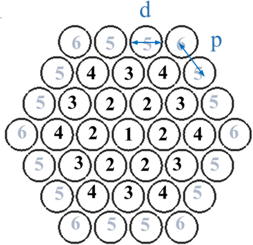
FIGURE 3. Rod number for a hexagonal array.
The absorption factors in a hexagonal array as shown in Figure 3 are defined as follows:
g11 is the fraction of the energy absorbed by rod No. 1 from the emission of rod No. 1.
g12/g13/g14 are the fraction of the energy absorbed by rod No. 2/No. 3/No. 4, respectively, from the emission of rod No. 1.
The absorption matrices for enclosed hexagonal arrays can be constructed from g11/g12/g13/g14. So next, we will introduce the derivation process to get these basic absorption factors.
The basic unit for studying the rod-to-rod absorption factor is illustrated in Figure 4A. In this unit, every individual rod is divided into six segments in the circumferential direction, and the surface 2/6/8/12/14/18 are the imaginary surfaces introduced to form an enclosure.
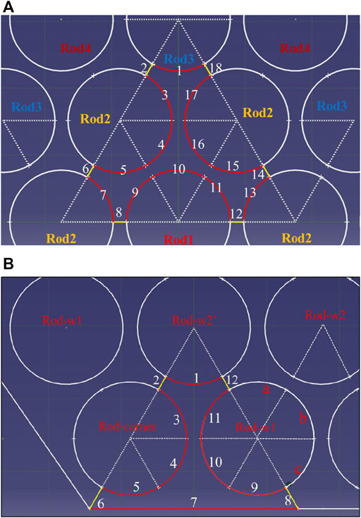
FIGURE 4. Basic unit for analyzing (A) the rod-to-rod absorption factors and (B) the rod-to-wall absorption factors.
The computational procedure for rod-to-rod basic absorption factors can be described as follows:
First, calculating the segment-to-segment view factors F (18 × 18) (surfaces 1/2/…/18, the detailed expressions are described in the Supplementary Appendix A, which is only related to p/d).
Next, calculating the segment-to-segment absorption factors SG (18 × 18) by using the matrix relationship Eqn. 13.
Then, calculating the basic absorption factors (g11/g12/g13/g14) by summing the corresponding segment-to-segment absorption factors:
In the above equations for calculating g11-g14, the segment-to-segment absorption factor related to surfaces 2/6/8/12/14/18 is an approximate treatment. For compact arrangement, the areas of surfaces 2/6/8/12/14/18 are relative small comparing with 1/6 rod segments. The unaccounted fraction absorbed by these areas is added to the neighboring rods. For example, the factor 1/2 in Eqs. 14, 15 can be explained using the energy absorbed by surface 8 and surface 12 from the emission of surface 10 being added to the two neighboring rods, Rod1 and Rod2. The factor 2/3 in Eqn. 15 can be explained using the energy absorbed by surface 6 and surface 14 from the emission of surface 10 being added to the three neighboring rods, among which two are Rod2 and the other one is Rod3. By the same token, 1/3 is chosen for surface 2 and surface 18 in Eqs. 15, 16. The reason for 1/6 in Eqs. 15–17 is that there are 6 rods marked as Rod2/Rod3/Rod4 around Rod1 in Figure 3.
The derivation here only goes to g14. Therefore, g14 is derived from g11 + 6*g12 + 6*g13 + 6*g14 = 1 according to the conservation of energy. It should be mentioned that the basic rod-to-rod absorption factor derived from Figure 4A is only applicable for compact rod bundles (p/d < 1.2). As p/d increase, a larger fraction of radiation energy will escape through these imaginary surfaces, but the basic unit shown in Figure 4A will limit the dispersal of radiation energy. For larger p/d (> 1.3), more radiative rods in the basic unit analyses need to be considered.
Figure 4B is the basic unit for analyzing the rod-to-wall absorption factors.
Defining Wg1, Wg2, and Wgcorner are the fraction of the energy absorbed by the wall from the emission of the rod near the wall in the first row, the second row, and the diagonal corners, respectively.
The computational procedure for rod-to-wall basic absorption factors is the same as the steps for rod-to-rod basic absorption factors.
First, calculating the segment-to-segment view factors F (12 × 12) (surfaces 1/2/…/12, the detailed expressions are described in the Supplementary Appendix B).
Next, calculating the segment-to-segment absorption factors SG (12 × 12) by using the matrix relationship Eqn. 13.
Then, calculating the basic absorption factors (Wg1, Wg2, and Wgcorner) by summing the corresponding segment-to-segment absorption factors:
For Rod-w1 in Figure 4B, the fraction of the energy absorbed by the wall should be the average fraction of six surfaces 9/10/11/a/b/c. While the surface a is totally on the opposite side of the wall, its contribution to Wg1 can be ignored. The contribution of surfaces b and c are equal to the part of surfaces 3 and 4. So, Wg1 is expressed as Eqn. 18.
For Rod-w2 in Figure 4B, the fraction of the energy absorbed by the wall should be one-sixth of the fraction of surface 1. But for Rod-w2’, the absorption factor should be 2*Wg2.
For Rod-corner, the total fraction absorbed by the wall should be the average fraction of surfaces 3, 4, and 5.
Similarly, the rod-to-wall absorption factor calculation shown here is only suitable for tight wall distance. The improvement of wall effect will be introduced in subsequent studies.
After getting the basic rod–rod and rod–wall absorption factor, we can construct the absorption factor matrices for enclosed hexagonal arrays.
Figure 5 is a schematic diagram of the cross-section of fuel rod bundles in an enclosed hexagonal array. There are 217 fuel rods in total. The rod surfaces can be numbered as 1–25 when the heat generation and boundary temperature are uniform, where rods with the same number are considered as one surface of uniform temperature.
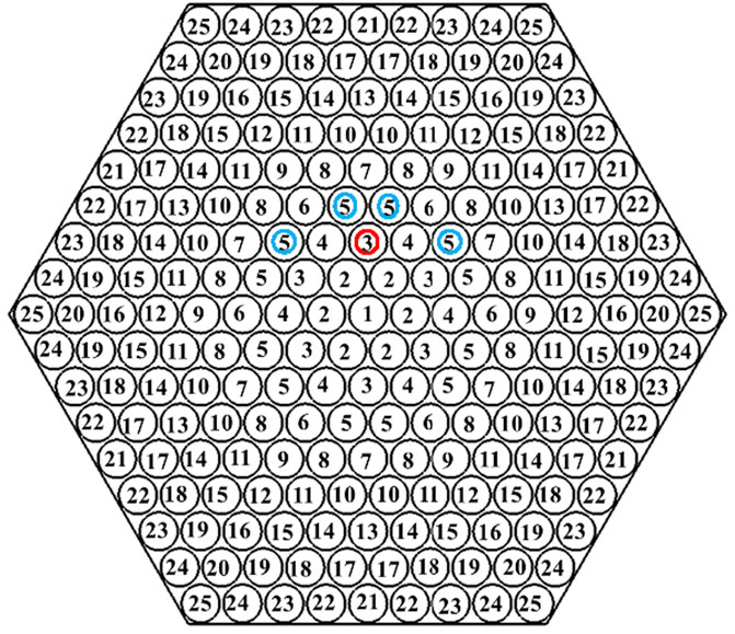
FIGURE 5. Cross-section of an enclosed hexagonal array and rod numbers.
Gi,j represents the absorption factor matrices for the hexagonal arrays. For compact fuel rod bundles, it is assumed that the radiation heat transfer within three rows is important. Then all the absorption factors Gi,j can be calculated from g11/g12/g13/g14. For example, G3,5 = 2*g12 + 2*g14. For each of the rods labeled as No. 3 as shown in Figure 5, two surfaces labeled as No. 5 have the same relative relationship with No. 3 as that between No. 2 and No. 1. Another two surfaces labeled as No. 5 have the same relative relationship with No. 3 as that between No. 4 and No. 1.
According to the fuel rods arrangement, the absorption factor matrix of the whole array constructed from g11/g12/g13/g14 to construct are presented in Figure 6.
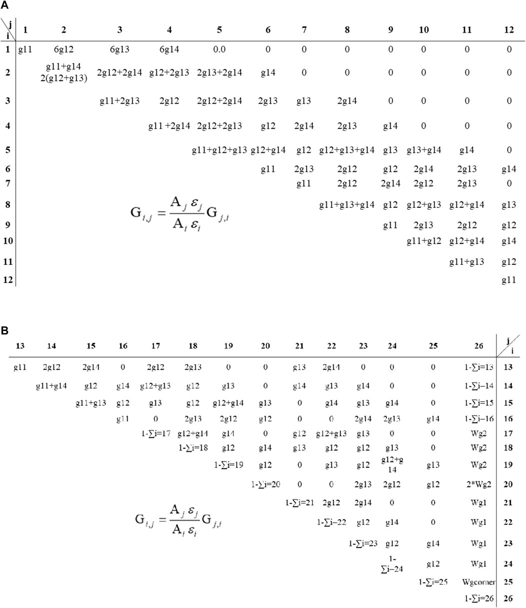
FIGURE 6. Absorption factor matrix for a hexagonal array: (A) interior and (B) near the wall.
The default model of RELAP5 for solving radiation heat transfer is based on the net heat method with the view factors (Information Systems Laboratories, 2003). We have modified its code and expanded its capability. The absorption factors matrix can be written in the input cards, and Gebhart’s method can be chosen to solve the radiation heat transfer between the surfaces.
In this part, Gebhart’s method is used to simulate the radiation heat transfer between rod bundles using the absorption factor matrix derived from Section 3.
The hexagonal array shown in Figure 5 was considered. In the preliminary research stage, it is simplified as a two-dimensional problem, which means the fuel rod bundles are infinitely long in the axial direction. The modeling details are outlined as follows: the diameter of each fuel rod d is 15.5 mm and the center distance between the fuel rods p = 1.1*d. The fuel rods are given a uniform power of 0.8 MW/m3 and a steady state solution was obtained with an imposed wall temperature of 573.0 K. The thermal conductivity of the material is assumed to be 1.0e6 W/(m·K) to eliminate temperature variations around the circumference of each rod. Each rod surface can be thought as isothermal.
Both the net radiation method (RELAP5) and Gebhart’s method (RELAP5 with Absorption Factor) were chosen for calculation. In addition, a detailed modeling of the radiation heat exchange was also carried out using CFD software FLUENT. For the RELAP5 and FLUENT simulation, the coolant should be included but the coolant in the enclosure neither emits nor absorbs radiant thermal energy. The surface-to-surface (S2S) radiation model based on the net radiation method was chosen in FLUENT, if N is considered as the number of subdivisions of a single rod surface. When using FLUENT to simulate the thermal radiation for hexagonal array shown in Figure 5, the number of mesh elements is 100,872, and the mesh schematic diagram is displayed in Figure 7. Each single rod is subdivided into N = 40 areas along the circumferential direction. Meanwhile, for the simulation of the default RELAP5 (the net radiation method) and the modified RELAP5 (Gebhart’s method with absorption factor), each individual fuel rod is treated as a unit; therefore, 25 + 1 = 26 elements are adopted, in which the additional one is the enclosed wall. The pair view factors of infinite parallel cylinders for the default RELAP5 simulation can be obtained from the work of Cox (1977). It is worth noting that in the default RELAP5 (the net radiation method), N is equal to 1 as the uniform radiosity over the entire circumferential surface of individual rod is assumed. Whereas, in the modified RELAP5 (Gebhart’s method with absorption factor), N is equal to 6 as the absorption factor matrix derived from Section 3 is based on the one-sixth rod.
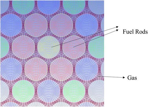
FIGURE 7. Schematic diagram of CFD mesh.
Figure 8 shows the surface temperature distribution of rod bundles calculated from RELAP5, the modified RELAP5 (with absorption factor), and FLUENT. It can be found that the temperature gradient between rod bundles calculated by RELAP5 is much lower than that calculated by FLUENT, which demonstrates that the uniform radiosity assumption over the entire rod overestimates the radiation heat transfer effect between rod bundles and thus under-predicts the rod temperature. The max error is up to 23% (∼440K). This is undesirable for the safety analysis of the reactor. With the increase in emissivity, the error will gradually decrease. The source of the error in uniform radiosity assumption is that the reflected radiation on the surface over the entire rod is not uniform. The radiosity due to reflection is proportional to the surface reflectivity
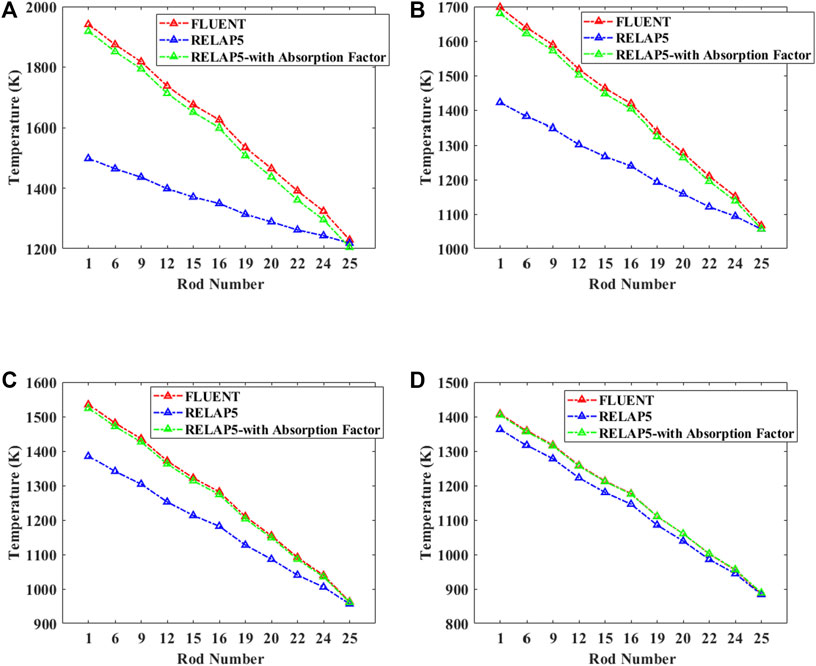
FIGURE 8. Temperature results for p/d = 1.1: (A) emissivity = 0.3, (B) emissivity = 0.5, (C) emissivity = 0.7, and (D) emissivity = 0.9.
In contrast, the temperature gradient calculated with the modified RELAP5 based on the absorption factors derived in this study is much closer to the CFD results under different emissivity. Which means that the calculation procedure proposed in this study can reduce the non-uniform radiosity error greatly.
Figure 9 presents the comparison of rod-to-rod absorption factors from different N for ε = 0.5 at p/d = 1.1. It can be seen that N = 6 in this study obtains a reasonable accuracy compared with the benchmark, that is, N = 40. In addition, the figure also indicates that a higher proportion of the radiation to be absorbed by the radiating rod itself and neighboring rods for compact rod arrangement. However, the default model (N = 1) overestimated the radiation domain of the radiating rod. In consequence, the predicted temperature is much flatter than the more divided results.
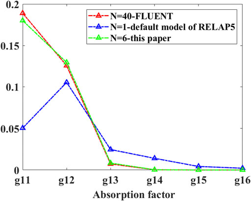
FIGURE 9. Absorption factors from different N for p/d = 1.1 and emissivity = 0.5.
Figure 10 describes the simulation results when p/d = 1.2. It can be seen that the simulation results based on the absorption factor are still much closer to CFD. Figure 11 shows the simulation results for p/d = 1.3. With the increase of P/d, the simulation results based on the absorption factor gradually deviate from the CFD results.
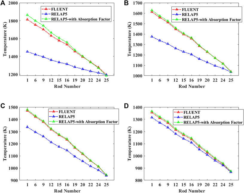
FIGURE 10. Temperature results for p/d = 1.2: (A) emissivity = 0.3, (B) emissivity = 0.5, (C) emissivity = 0.7, and (D) emissivity = 0.9.
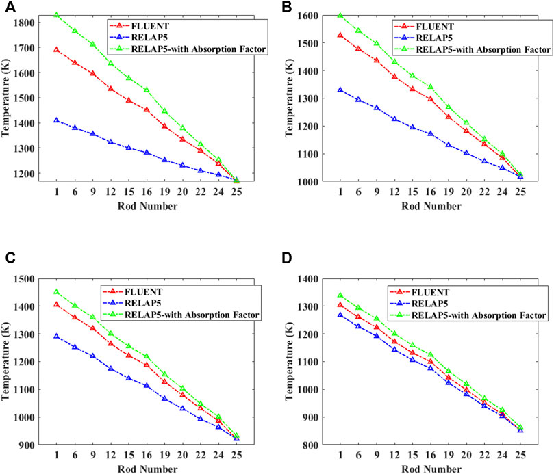
FIGURE 11. Temperature results for p/d = 1.3: (A) emissivity = 0.3, (B) emissivity = 0.5, (C) emissivity = 0.7, and (D) emissivity = 0.9.
The relative temperature error of Rod 1 was summarized in Table 1. The uniform radiosity assumption over the entire rod overestimates the radiation heat transfer effect between rod bundles and thus under-predict the rod temperature. The max temperature under-predictions are about 23%, 20% for p/d = 1.1, 1.2, respectively. While using the absorption factor matrix derived in this study, the maximum temperature deviation can be reduced to around 1% for p/d = 1.1 and 3% for p/d = 1.2.
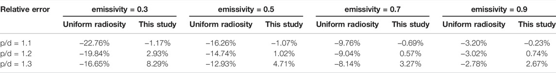
TABLE 1. Relative temperature error of rod No.1.
As p/d increase, the radiation heat will transfer farther; thus, the temperature gradient between rod bundles decreases. As a result, the non-uniform radiosity error will gradually decrease, but still underestimate the temperature around 17% for p/d = 1.3. The absorption factor derived in this study will overestimate the maximum temperature about 8% for p/d = 1.3. The reason has been explained in Section 3. With the increase in p/d, there is actually a wider dispersal of energy, but our derivation only goes to g14. So, the temperature results calculated with the absorption factors for p/d = 1.3 are steeper and higher than that calculated by CFD. Rod bundles with larger p/d required more radiative rods in the deprivation of absorption factors.
Radiation heat transfer is an important heat transfer mechanism in the open-lattice gas-cooled reactors. The uniform radiosity assumption of each fuel rod will overestimate the heat transfer and thus under-predict the maximum fuel rod temperature, which is not expected in safety analysis. To reduce the non-uniform radiosity error, construction of absorption factor matrices based on 1/6 rod segments have been developed in this study.
Gebhart’s method was implemented in RELAP5 and was used to simulate the radiation heat transfer between rod bundles. It is found that the simulation results based on the absorption factor matrices deprived in this study can reduce the non-uniform radiosity error greatly for compact rod bundle arrangement (p/d < = 1.2). Rod bundles with larger p/d required more radiative rods in the analyses of basic absorption factor modifications. The present radiation heat transfer model should be studied and tested in three-dimension cases to further prove that it is appropriate for the nuclear rod bundles.
The original contributions presented in the study are included in the article/Supplementary Material, further inquiries can be directed to the corresponding author.
All authors contributed to the article and approved the submitted version.
This work was supported by NSFC No. 52106256, the China Postdoctoral Science Foundation (2020M680586), and the CNSA program (D010501).
The authors declare that the research was conducted in the absence of any commercial or financial relationships that could be construed as a potential conflict of interest.
The reviewer SH declared a shared affiliation, with no collaboration, with the authors to the handling editor at the time of the review.
All claims expressed in this article are solely those of the authors and do not necessarily represent those of their affiliated organizations, or those of the publisher, the editors, and the reviewers. Any product that may be evaluated in this article, or claim that may be made by its manufacturer, is not guaranteed or endorsed by the publisher.
The Supplementary Material for this article can be found online at: https://www.frontiersin.org/articles/10.3389/fenrg.2022.841631/full#supplementary-material
Andersen, J., and Tien, C. L. (1979). "Radiation Heat Transfer in a BWR Fuel Bundle under LOCA Conditions," in Fluid Flow and Heat Transfer over Rod or Tube Bundles Conference at ASME, Simulation, New York, NY, December 2‐7, 1979, 199–207.
Ashcroft, J., and Eshelman, C. (2006). Summary of NR Program Prometheus Efforts. Naval Reactors Program 3, 83–87. doi:10.2172/881290
Cox, R. L. (1977). Radiative Heat Transfer in Arrays of Parallel Cylinders. [dissertation]. Knoxiville (Tennessee): University of Tennessee.
Dragunov, Y. G. (2015). Fast-neutron Gas-Cooled Reactor for the Megawatt-Class Space Bimodal Nuclear thermal System. Eng. Autom. Probl. 2, 117–120.
Dragunov, Y. G. (2021). Space Nuclear Power. Her. Russ. Acad. Sci. 91, 327–334. doi:10.1134/s1019331621030035
El-Genk, M. S., and Tournier, J.-M. (2008). Noble Gas Binary Mixtures for Gas-Cooled Reactor Power Plants. Nucl. Eng. Des. 238 (6), 1353–1372. doi:10.1016/j.nucengdes.2007.10.021
Information Systems Laboratories (2003). RELAP5/MOD3.3 Code Manual, Vol. 1: Code Structure, System Models, and Solution Methods. NUREG/CR-5535/Rev P3-Vol I. Idaho: National Engineering Laboratory.
Klepper, O. H. (1963). Radiant Interchange Factors for Heat Transfer in Parallel Rod Arrays, ORNL-TM-583. Oak Ridge, TN: Oak Ridge National Laboratory.
Manteufel, R. D. (1991). Heat Transfer in an Enclosed Rod Array. [dissertation]. Cambridge (Massachusetts): Massachusetts Institute of Technology.
Meng, T., Zhao, F., Cheng, K., Zeng, C., and Tan, S. (2019). Neutronics Analysis of Megawatt-Class Gas-Cooled Space Nuclear Reactor Design. J. Nucl. Sci. Technol. 56, 1–10. doi:10.1080/00223131.2019.1644244
Naitoh, M., Kawabe, R., and Chino, K. (1977). Analysis of Radiant Heat Transfer in a BWR Fuel Assembly. Nucl. Eng. Des. 44 (3), 315–321. doi:10.1016/0029-5493(77)90167-4
Qin, H., Zhang, R., Guo, K., Wang, C., and Qiu, S. (2020). Thermal-hydraulic Analysis of an Open-Grid Megawatt Gas-Cooled Space Nuclear Reactor Core. Int. J. Energ. Res. 45, 11616–11628. doi:10.1002/er.5329
Rector, D. R. (19871987). RADGEN: A Radiation Exchange Factor Generator for Rod Bundles. Richland, Washington: Pacific Northwest Laboratory.
Sohal, M. S. (1986). Radiation Heat Transfer Model for the SCDAP Code. Nucl. Technol. 75, 2. doi:10.13182/NT86-A33862
Stanculescu, A. (2005). The Role of Nuclear Power and Nuclear Propulsion in the Peaceful Exploration of Spac. Vienna: International Atomic Energy Agency.
Tien, C. L., Sanchez, R. A., Mandell, D. A., and McDaniel, C. T. (1979). Surface Radiative Exchange in Rod Bundles. Trans. Asme, J. Heat Transfer 101, 378–379. doi:10.1115/1.3450981
Tournier, J. M., El-Genk, M., and Gallo, B. (2006). “Best Estimates of Binary Gas Mixtures Properties for Closed Brayton Cycle Space Applications,” in 4th International Energy Conversion Engineering Conference and Exhibit (IECEC), San Diego, California, June 26 - 29, 2006.
Watson, J. S. (1963). Heat Transfer from Spent Reactor Fuels during Shipping: A Proposed Method for Predicting Temperature Distribution in Fuel Bundles and Comparison with Experimental DataORNL-3439. Oak Ridge TN: Oak Ridge National Laboratory.
Keywords: fuel rod bundles, radiation heat transfer, non-uniform radiosity, absorption factor, RELAP5
Citation: Sun Q, Ji Y and Sun J (2022) Improved Radiation Heat Transfer Model in RELAP5 for Compact Fuel Rod Bundles by the Absorption Factor Modification. Front. Energy Res. 10:841631. doi: 10.3389/fenrg.2022.841631
Received: 22 December 2021; Accepted: 11 April 2022;
Published: 27 April 2022.
Edited by:
Yue Jin, Massachusetts Institute of Technology, United StatesReviewed by:
Shanfang Huang, Tsinghua University, ChinaCopyright © 2022 Sun, Ji and Sun. This is an open-access article distributed under the terms of the Creative Commons Attribution License (CC BY). The use, distribution or reproduction in other forums is permitted, provided the original author(s) and the copyright owner(s) are credited and that the original publication in this journal is cited, in accordance with accepted academic practice. No use, distribution or reproduction is permitted which does not comply with these terms.
*Correspondence: Jun Sun, c3VuanVuQHRzaW5naHVhLmVkdS5jbg==
Disclaimer: All claims expressed in this article are solely those of the authors and do not necessarily represent those of their affiliated organizations, or those of the publisher, the editors and the reviewers. Any product that may be evaluated in this article or claim that may be made by its manufacturer is not guaranteed or endorsed by the publisher.
Research integrity at Frontiers
Learn more about the work of our research integrity team to safeguard the quality of each article we publish.