 Jun Li
 Hal Gurgenci
 Zhiqiang Guan2
- 1School of Mechatronics Engineering, Henan University of Science and Technology, Henan Key Laboratory for Machinery Design and Transmission System, Henan University of Science and Technology, Luoyang, China
- 2School of Mechanical and Mining Engineering, University of Queensland, Brisbane, QLD, Australia
This paper presents the results of a numerical study on a supercritical CO2 (SCO2) turboshaft cooling device by considering heat transfer and hydrodynamics. A micro-cooling device with a radius clearance of 50 micron and a nozzle diameter of 4 mm was designed and used to investigate the heat transfer characteristics of a micro-spacing impinging and gas film dynamics. Sixteen nozzles (N = 16) are equally spaced around the shaft in single or double rows. Investigations include journal speed- and eccentricity-dependent forward and cross-coupled force coefficients, and the effects of nozzle layouts and mass flow rate on the heat transfer efficiency. Analysis of the correlation coefficient shows that the gas density in the radial clearance is the dominant factor affecting the convective heat transfer performance, while the fluid velocity is a secondary factor. And the cooling efficiency (mass flow utilization rate) at low cooling pressure (ps < 0.7 MPa) is significantly greater than that at high cooling pressure (ps > 0.7 MP). In addition, considering the structure alone, a dual-row cooler exhibits a higher average Nusselt number, also registers a higher mass flow rate at the same pressure. Once the shaft is heated only one end, the difference in effectiveness between single- and dual-row cooling is not significant, so coolers with a single-row configuration should be preferred. Then, experimental values for the temperature of the heated rotor are provided under specific cooling airflow conditions. Dynamic analysis results show that the force coefficient of the single-row configuration is more dependent on the journal rotation speed and eccentricity ratio, and exhibits a negative direct stiffness coefficient at higher inlet pressure and journal rotation speed. Moreover, cross-coupled terms (stiffness coefficient) generally have a more explicit variation tendency than direct terms, and are more sensitive to changes in shaft speed and eccentricity. Small clearance cooling is a relatively complex technology aimed to improve heat dissipation efficiency in gas cooling devices while minimizing the effect of hydrodynamic pressure. Comparing the gas force coefficients of different journal speeds reveals a drastic increase in the effect of hydrodynamic pressure when the journal is eccentric. The cooler may be considered for operation with compliant support (such as bump foil) to generate additional damping and appropriately compensate for the eccentricity of the rotor.
Introduction
The supercritical carbon dioxide (SCO2) cycle has attracted widespread attention owing to its enhanced efficiency at higher turbine inlet temperatures, and its effective utilization in various next generation power plants, such as nuclear, fossil fuel, waste heat, and renewable heat sources (Turchi et al., 2013; San Andres et al., 2011a; Ahmadi et al., 2018; White et al., 2021; Ahn et al., 2015). Numerical (Alawadhi et al., 2021; Khatoon et al., 2021), experimental (Marchionni et al., 2021; Arslan and Guzel, 2021), and theoretical (Lee et al., 2021; Persico et al., 2021) investigations have probed into various fundamentals as well as practical applications of SCO2 Brayton cycles. Multiple factors make SCO2 a preferred circulating medium for next generation of power conversion systems including smaller heat exchangers, simple physical layouts, reliability and safety with conventional structure materials, compact turbomachinery and high efficiency at the higher turbine inlet temperatures (500–900
The supercritical CO2 turbine configuration adopted by the Australian Solar Thermal Research Institute (ASTRI) is a radial turbine where the rotor is mounted at the end of an overhung shaft (Figure 1). In order to meet the conventional bearings and dry gas seals requirement on temperature, a cooling zone is provided between the impeller on the cantilever and the dry gas seal. The cooler proposed in this paper aims to protect the dry gas seals and the bearings inside the gearbox against the high temperatures at the turbine exhaust.
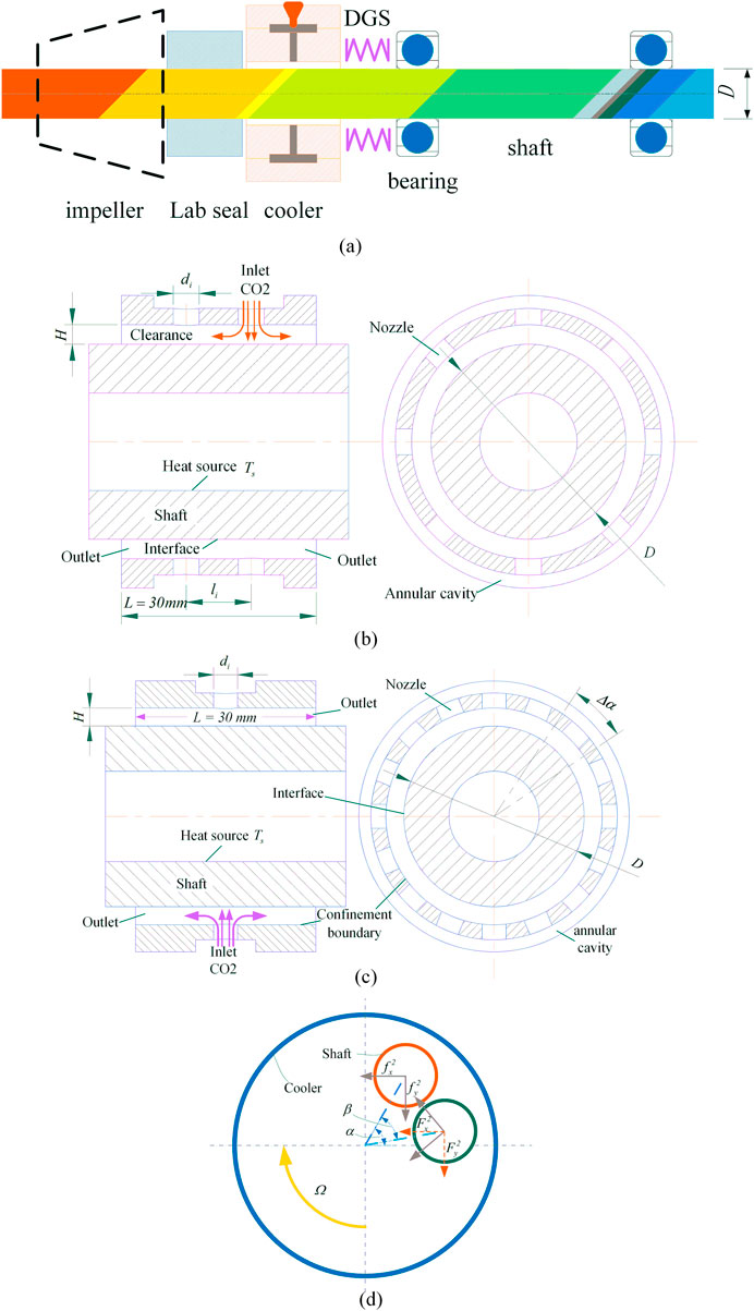
FIGURE 1. Working mechanism of the proposed cooler and shafting for SCO2 turbine. (A) Schematic diagram of bearing-rotor system. (B) double row. (C) single row. (D) Schematic graph of rotating frame with cooler describing a journal with amplitude e and attitude angle
Besides of the thermal management for the dry gas seal and the bearings, the paper will also propose the use of a “cooling device” to add extra stiffness to support the rotor of the turbine. By “Cooling device”, it means a high-clearance journal bearings with cool CO2 flowing through the annulus passage to cool the shaft. The cooler is not a true journal bearing. Its clearance is selected to provide adequate cooling. The flow in the annular passage in the cooling device will be simulated using computational fluid dynamics (CFD). The cooling device stiffness and damping values (as predicted in CFD) are combined with the shaft model of SCO2 turbine. The results will give the predicted critical speed and damping for the SCO2 turbine. Before that, the convective heat transfer characteristics of the cooling device should be studied in detail. The unbalanced response of the turbine impeller and the cooling efficiency of the cooler are being influenced by the impingement separation distance of nozzle and shaft surface, and the velocity in the radius clearance (Figure 1) is affected by the conversion of pressure gradient with the momentum. In addition, the flow structure is more intricate as the jet impingement are impacted by adjacent wall jets and micro scales limiting the average velocity of the fluid (Adeoye et al., 2021).
The reasons for instability in hot turbines, in addition to unbalanced mass on the cantilever, may be a resonance, misalignment and a too high shaft temperature. A very important issue is the thermal creep and uneven thermal expansion of the structural components during hot turbine operation. To control temperature gradient of the gas foil bearings, Lubieniecki et al., 2016 and Martowicz et al. (2020) proposed a method of thermoelectric coolers. With a traditional but effective approach, Ryu (2012) implemented a thermal management in gas foil bearings system which is to supply pressurized air inside the bearing to control thermal growth of foils. A similar case, San Andres et al. (2011b) presented full details on the test data and analytical results for dynamic and thermal performance of gas foil bearings system with a cooling gas stream condition.
Most of the previous numerical and experimental studies have reported a high heat transfer coefficient in the jet impingement cooling region, which have been used in various industrial applications (GhadikolaeiAlotaibi et al., 2020; 2021; Maghrabie, 2021; Modak et al., 2021). Several studies have also explored micro-scale impinging jets and reported a significantly different heat transfer characteristics compared to the results obtained at the normal scale. Lau et al. (2021) reported an enhanced overall cooling performance for a water jet with Al2O3 nano-fluid in their study of heat transfer enhancement on a microchannel single synthetic jet impinging. Adeoye et al. (2021) experimentally studied micro-nozzle (206 μm) impingement on a thick fused silica substrate with supercritical carbon dioxide and noted the differences between available correlations and experiments. Patil and Narayanan (2005) compared experimental average Nusselt numbers (Nuav) of microscale circular nozzle (nozzle diameter di = 125 μm) jet impingement to the earlier investigation of Martin and noted that there were notable deviations for the both low Reynolds numbers (Re) and high Re normal scale jet impingement. A numerical study by Li et al. (2021) reported significant enhancements of the heat transfer for CO2 jet impinging when the separation distance between nozzle and target surface was reduced from 0.1 to 0.05 mm. However, it is rare to study the heat transfer performance of gas films in the radial clearance between rotating shaft and cooler.
A previous study (Kim et al. (2019) has shown that a single-phase hybrid micro array jet impingement can attain strong impingement effects caused by reduced diameter of jet nozzles. However, the nozzle-to-surface spacing is still mainly responsible for the heat transfer efficiency for a given mass flow rate (Ahmed et al., 2021). Although this conclusion demonstrates the high performance of hybrid micro-scales with water for cooling, its compatibility with gas cooler of rotor systems remains a concern. For the SCO2 turbine rotor shaft cooling, the multi-nozzle is employed in the pattern of a row or array jets evenly distributed around the shaft (Figure 1). For this reason, gaseous refrigerant, such as supercritical carbon dioxide in the Brayton cycle has been taken into consideration, but because of the high pressure (the CO2 critical condition is 30.98
Experimental and numerical investigations have been carried out on several different configurations to study the dynamic performance of gas film, such as gas foil bearings (Basumatary et al., 2020; Zhang et al., 2018; Zywica et al., 2021), self-acting gas journal bearings (Feng et al., 2017; Zhang et al., 2014), and other externally pressurized gas bearing (Moore et al., 2011; Han et al., 2014; Ise et al., 2014). Although the pressure distribution of the gas film obtained numerically with standard Reynolds equation is approximately to determine the stiffness and damping, the thermally coupled analysis of the bearing may be impeded. In the model of the cooler, the radius clearance (50
To sum up, a reliable implementation of conventional bearings (such as gas foil bearings, angular contact ball bearings and oil film bearings) and seals into high temperature SCO2 turbomachinery requires effective thermal management to maintain rotor system stability. Another purpose of this paper is to tailor the cooler stiffness in both forward and cross directions, thereby minimizing the dynamic pressure effect of gas film, to maintain a reasonable compliance and accommodate mechanical distortions as well as misalignment of the shafts. The cooler proposed in this paper is inspired by the external gas bearing and jet impingement, as the coolant is a high-pressure CO2 gas, with the impinging jet is normal to the surface of the shaft. There are constrains on the radius clearance between the shaft surface and the nozzle mounting surface (confinement surface) to provide additional throttling effect for the cooling device and improve the cooling efficiency of the airflow.
The Physical Problem and Method of Analysis
Computational Fluid Dynamic Modeling and Boundary Conditions
The cooler consists of 16 nozzles assembly oriented normal to the rotor shaft surface. The geometry of the fluent model is symmetry with the axis as shown in Figure 1. However the circumferential symmetry only happens when the shaft is at the geometric center of the cooler, dynamic pressure effect of gas film is inevitably caused by the rotating speed and displacement of the shaft. The dynamic pressure effect of minimum gas film thickness between shaft surface and the bearing inner surface provides cross force may well in excess of forward force obtained around the nozzle. The symmetry of the gas film dynamics no longer exists. And, the negative cross-acting force promotes the whirl of the rotor is also one of the important factors of system instability. Hence, full of the inlet, nozzles, clearance are modeled as real CO2 gas fluids in commercial CFD software, and shaft is modeled as steel solid. The hollow shaft is the superficial heat generating source and the constant amount of temperature is 1073 K in core. Inlet of nozzles is the momentum source of jets which is set as a pressure inlet or mass flow rate conditions. The outlet boundary condition is set to a pressure of 0.1 MPa. An isothermal no-slip boundary condition was assumed with the rotor surface and adiabatic condition for the other walls. With the purpose of getting a comprehensive investigation for the stiffness, damping and heat transfer efficiency in the micro-clearance jet impingement, the CFD software Fluent 19.1 and computer cluster have been utilized. The nozzle rows, the jet-to-surface spacing and rotation speed of shaft are variable to assess how they have impacts on heat transfer rate and kinetic characteristics of gas film. Several different combinations of boundary conditions and nozzle configurations were considered as summarized in Tables 1 and 2.
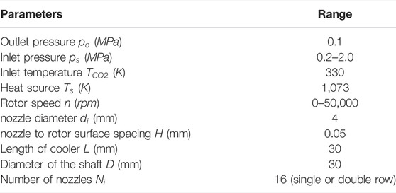
TABLE 1. Boundary conditions and parameter values for the numerical studies.
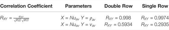
TABLE 2. Correlation coefficients between the average Nusselt number and the variables analyzed.
Governing Equation
As a conclusion of the previous experimental and numerical preliminary investigation, that the ideal turbulence model does not exist, as is commonly asserted in a jet impingement analysis (Ehsan et al., 2019).As a compromise, many investigations have concluded that Reynolds-averaged k-omega turbulence model shows reasonably admissible performance in gas jet impact prediction (Lapka et al., 2020; Tepe, 2021; Tepea et al., 2020). Considering the complex flow of jet impact and the high-speed rotation of the shaft, the flow in the computational domain was depicted by the k-omega model (Lapka et al., 2020). The governing equations in the computation are the Reynolds-averaged mass, momentum, and energy. The equations with steady-state compressible fluid properties are expressed as:
Continuity Equation:
Momentum Equation:
Where,
Energy Equation:
Where,
The Reynolds number of nozzles is defined as follows:
Where,
Where
FIGURE 2. Grid refinement and experimental verification. (A) Reynolds number distribution vs. parameters, (B) Grid independence study for the numerical computation, (C) Experimental data vs. CFD results of load capacity.
The dimensionless convective heat transfer rates along the cooled rotor surface are defined in terms of the Nusselt number, and the local
Averaged Nu number can be determined as:
Where,
Analysis of Gas Film Forced Performance
The wall boundary conditions for the gas film are the stationary wall and the rotating surface on the inner wall of the bearing and the surface of the shaft, respectively. In the case of gas bearing, dynamic gas forces are calculated based on the shaft eccentricity and whirling velocity perturbations. It can be defined as the following:
Where,
Accordingly, the damping and stiffness in the thin film is assumed to behave as linear changes at the occurrence of minor perturbations, and hence the equation of followings (Eqs. 10–19) are used to express the kinetic characteristics of gas film as a function of shaft’s displacement and whirling velocity disturbances. Damping can be expressed separately as
Where,
Hence, the stiffness coefficients, at eccentricity [
Where,
In order to introduce a variable whirl frequency, the components of rotor rotational velocity must be coupled to the translational velocity, and the coupled motion is solved for the boundary condition of the shaft surface after considering the displacement disturbance. The translational velocities over each steady state position is determined by the whirl frequency as
For a rotating journal operation, the surface gas flow circumferential velocities vary along the Cartesian coordinate x and y as
Where,
The coupled velocities
The number of modeling and the amount of numerical calculation were reduced by application of the rotating coordinate system (RCS) in the calculation of the stiffness coefficient. This section further details RCS methods for predicting stiffness coefficients from dynamic load. The prediction restricts its attention to cylindrical bearings.
Figure 1D depicts a schematic diagram of an extruded gas film with a journal describing a whirl motion with amplitudes ex and ey. This diagram involves two coordinate systems, one stationary (X, Y) and one rotation (x, y), with angle (
In a CFD analysis, the shaft journal kinematics
In the rotation coordinate (x, y), the deflection angle of the journal becomes
Then the relative displacement is
The dynamic equilibrium relations above reveal that the gas film thickness and its forces are angle-invariant in the rotating coordinate system. However, the estimation above is true only in a cooler configuration neglect of its anisotropy. The inlet gas flow distort the distribution of pressure; consequently, resultant force is no longer invariant in the rotating coordinate system. In other words, the periodicity of the cooler configuration does not exist at arbitrarily small Interval angles.
Grid Refinement and Experimental Verification
The grid independence examinations have been carried out to validate that the results are independent of the mesh element size. Nine grids with degressive element sizes of 0.12, 0.11, 0.1, 0.09, 0.08, 0.07, 0.06, 0.05 and 0.04 mm have been used to examine the mesh resolution independency. Average, maximum and Minimum Nusselt number
Since the micro-clearance jet impingement is a design similar to the external pressure gas bearing, there is a comparison in the published experimental data for the gas film dynamic characteristics of gas film. The externally pressurized gas bearing referred to in this verification is a rectangular slot restriction type. The actual dimensions and structure of this bearing are same as (Ise et al., 2014). The gas bearing load capacities were evaluated using the results of CFD (in this study) and test data. A symmetrical pressure region admission type journal bearing was used for the sample. The detailed bearing forced performance have been tested and solved numerically in the previous study, where the Reynolds equation was applied to describe the dynamic characteristics of the gas film. The solid line in Figure 2C shows the test results of the load capacity of the gas bearing relative to the eccentricity ratio for dimensionless inlet pressure
Results and Discussion
Thermal Performance of the Cooling Device
The thermal analysis of the cooling system proposed in the study is carried out based on the assumption that the journal is dynamically stable in the geometric center of the cooling device. The journal diameters and the cooler lengths used in the thermal analyses are both 30 mm (see Table 1). Due to the reduced distance between the inlet and outlet for double row cooler, the heat transfer capacity contribution from the mass flow rate increases. While the one with single row (inlet assumed to be located in the middle of the two outlet, see Figures 1B,C) has a longer throttling distance. Therefore, the combined effect of the density, velocity, and temperature difference of the fluid in the radial clearance should be considered. The Heat transfer performance of gas film is presented in terms of average Nusselt number of the fluid and journal coupling surfaces (Figure 1, interface).
Figure 3A compares the pressure-dependent surface-averaged Nusselt distributions. Compared to the single-row configuration, the
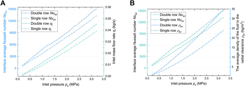
FIGURE 3. Convection heat transfer performance of dual-row and single-row coolers: (A) Interface average Nusselt number Nuav and inlet mass flow rate qi versus inlet pressure ps. (B) Nuav and Average density of gas in the radius clearance
The jet gas experiences notable velocity and density variations in the micro-radius clearance. Figures 4, 5 presents the averaged Nusselt number Nuav, average density
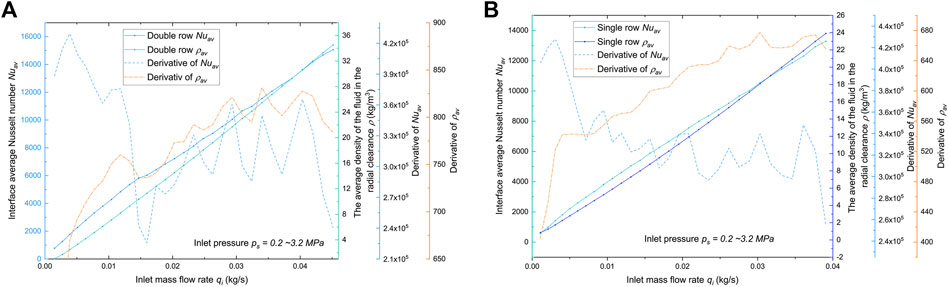
FIGURE 4. Factors affecting heat transfer efficiency: the average Nusselt number
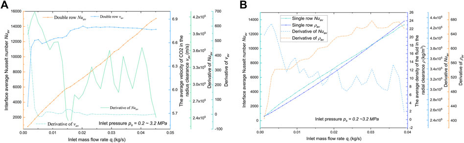
FIGURE 5. Factors affecting heat transfer efficiency: predicted
Further thermal analysis is performed on the solid shaft heated at the right end for the coolers of both configurations. The results of this investigation are shown in Figure 6. The average temperature at free end of journal with double row cooler is slightly higher (0.71% on average) due to half the nozzles away from elevated temperature. In addition, the total mass flow rate increased slightly (7.3% on average) over the entire pressure range compared to the single-row configuration. The maximum averaged temperature of free end are around 505 K (double row) and 503 K (single row) when cooling gas pressure supplied is only 0.2 MPa, while increasing the gas pressure to 0.7 MPa drops the average temperature significantly to around 368 K (double row) and 364 K (single row). Steps further on, the average temperature of free end can even be maintained below the temperature of coolant with an extremely high inlet pressure due to expansion of endothermic. However, it is noteworthy that the cooling efficiency of the cooler with low cooling pressure (ps < 0.7 MPa) is significantly larger than the case with high cooling pressure (ps > 0.7 MP). Higher pressure means more energy and gas wasted.
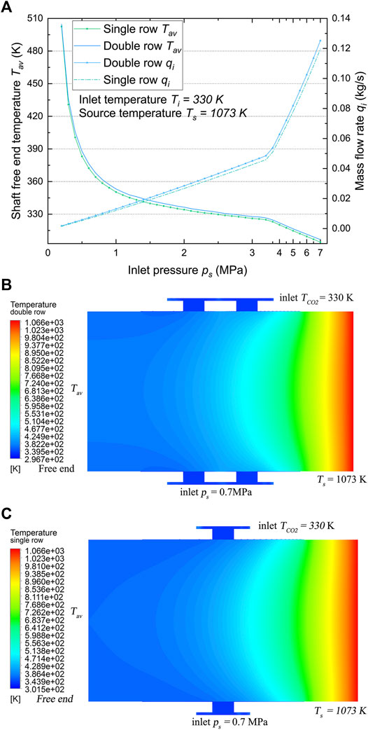
FIGURE 6. (A) Average temperatures Tav at the free end of journal and inlet mass flow rate qi versus inlet pressure ps. (B) The temperature field of the journal with a double-row inlet cooler. (C) The temperature field of the journal with a single-row inlet cooler. The cooling stream temperatures, TCO2 = 330 K. The temperature of the heat source, Ts = 1073 K.
In general, although the mass flow rate and average Nusselt number in cases 1 and 2 do differ significantly, the temperatures Tav do not (Figure 6A). Figures 6B,C shows the cooling system temperature field along the axial direction for both cases with inlet pressure of 0.7 MPa. The right end is in thermal contact to the hot impeller (Ts = 1073 K) and the left end (free end) is in thermal contact with the bearing unit (considered as adiabatic in this study). Due to the coolant injected into radius clearance flows out along the axial direction (both elevated and low temperature side), the rotor temperature sharply drops. The journal temperature has slightly higher thermal gradient along the axial direction for case with single row nozzles because of more cooling effect at the nozzle and at the location with the larger temperature difference. The tendency can also be observed in the shaft temperature field shown in Figure 6A. Demonstrated in the figures is the basic principle for impingement heat transmission that a stream impacts directly onto the target surface with thermal boundary layers to transfer heat efficiently.
Experiment
For the purpose of validating the mathematical model of the fluid in the journal cooler, the experiment was performed using one rotor test rig (illustrated in Figure 7A). In the test rig, a horizontal shaft rotation is automatically applied by an electro-spindle. The journal cooler is supported by a hub with a pressure transducers and a thermocouple. The cooling device is located in the middle of the cantilever of a rotor. The larger disc at the free end of cantilever is heated by electromagnetic induction at a restricted power of 1.6 kW. The cooler hub has a total of three radial threaded holes to supply the pressurized gas while allowing a transducers to be attached to gas in the annular cavity (Figure 1). The geometry of the tested cooler is presented in Figure 1C. With the Thermal imaging camera, temperature measurements of the shaft and the discs are examined in order to compare with the numerical results.
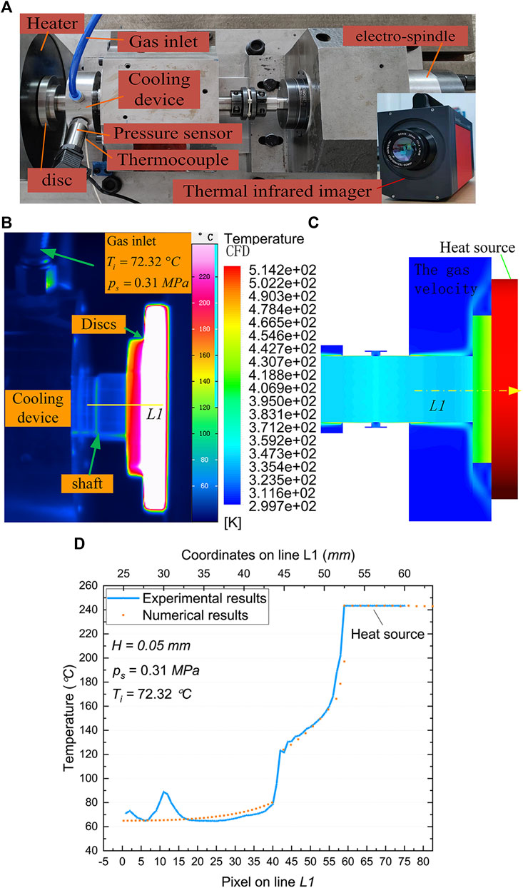
FIGURE 7. Experimental setup and results. (A) Test rig for the measurement of the temperature field of the rotor. (B) Experimental results. (C) Numerical results. (D) Experimental and numerical temperatures on the line L1.
Figures 7B,C shows the measured and the predicted temperature distribution of the cantilever. The temperature image is captured when the rotor is thermally balanced, this is important for the comparison. The current pressure and temperature of the gas in the annular cavity are measured by the thermocouple and pressure sensor. These parameters will be used as boundary conditions for numerical calculation. The large disc on the right is used as the heat source, and the temperature value adopts the steady-state temperature measured in the experiment. The line L1 in the figures is defined as temperatures of the cantilever in the direction of the center of the rotor, and its coordinate origin is on the left. The measured temperature on the horizontal line (L1) (see Figure 7B), is extracted on pixels. Figure 7D compares experimental and numerical temperatures on L1. These curves follow almost the same trend. It can be seen that both temperature curves (numerical and experimental) were subdivided into three main ranges. The range belonging to the shaft, is characterized by a small gradient, accompanied by small fluctuations (experiment results). This temperature is mainly determined by the cooling gas. The region belonging to the small disc is characterized by a significant increase in temperature gradient. The third region, located on the larger disc, remains roughly constant in temperature and can be considered a heat source. In this region, only a small gas flow is in contact with the surface.
As shown in the curves (Figure 7D), the numerical and measured temperature curve agree well. In the first region, slight deviation between CFD numeration and measurement exist. This might be traced back to shape difference and thermal resistance at the connection between the shaft and the disc which can cause uneven heat transfer. In addition, no temperature gradient of the large disc side surface are captured by the infrared thermal imaging camera.
Analysis of Dynamic Force Coefficients
This section discussed the force coefficient performance of cooling film versus eccentricity ratio and rotor speed for attitude angle of
The variation tendency of the stiffness coefficient kxx is relatively complicated. Hydrodynamic pressure caused by journal speed and static pressure from the nozzle have opposite effects on kxx. The eccentricity (stiffness comes from static pressure) is the dominant factor at low journal speed and the opposite at high speed. The competition between the two forces causes the curves in the graphs to be distorted. In general, it first increases and then decreases with increasing journal eccentricity. The peak occurs between an eccentricity ratio equal to 0.14 and 0.283, depending on the cooling pressure and rotor speed.
Figures 8, 9 present the forward stiffness coefficient kxx and kyy versus eccentric ratio for varying journal speeds, respectively. As the rotor speed increases from 0 to 60,000 rpm, the kyy (Figure 9) increases and kxx decreases at higher speeds, demonstrating that journal speed can significantly change the pressure distribution in the radius clearance. In particular, the principal stiffness coefficient kxx of the gas film is greatly reduced, for example, going from a maximum of
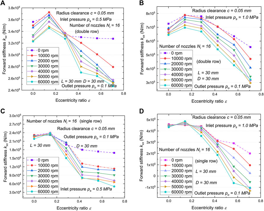
FIGURE 8. Variations of forward stiffness coefficient kxx with eccentricity ratio. (A) Double row, ps = 0.5 MPa. (B) Double row, ps = 1.0 MPa. (C) Single row, ps = 0.5 MPa. (D) Single row, ps = 1.0 MPa.
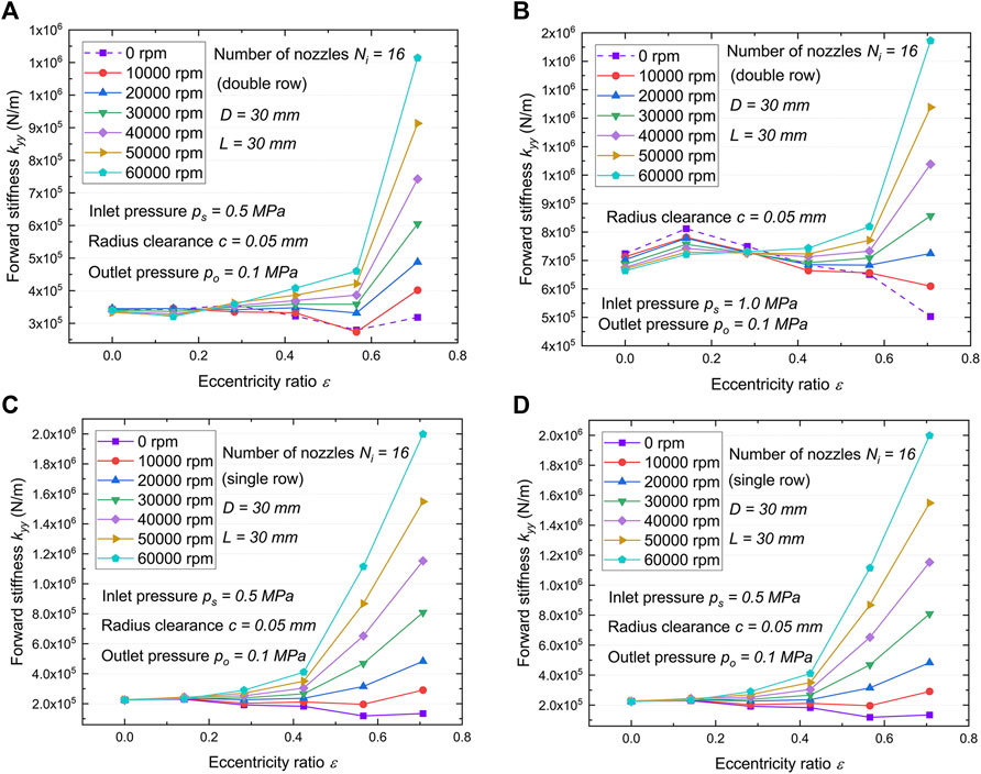
FIGURE 9. Variations of forward stiffness coefficient kyy with eccentricity ratio versus rotor speed. (A) Double row, ps = 0.5 MPa. (B) Double row, ps = 1.0 MPa. (C) Single row, ps =0.5 MPa. (D) Single row, ps =1.0 MPa.
A cooler model that does not consider hydrodynamic pressure effects will incorrectly estimate the force coefficient, due to the existence of unbalanced responses and misalignment of the rotor. Figures 10, 11 show the cross stiffness coefficient kxy and kyx versus eccentric ratio, respectively. In general, the cross stiffness coefficient increases with rotor speed and eccentric ratio while decreases with the number of nozzle rows. Cooler with the higher journal speed and stronger the gas film squeeze shows the larger kyy, kxy and kyx (absolute value), and the single row with the more concentrated the hydrodynamic pressure effect (See Figure 12) demonstrates the larger the cross-coupling force coefficient.
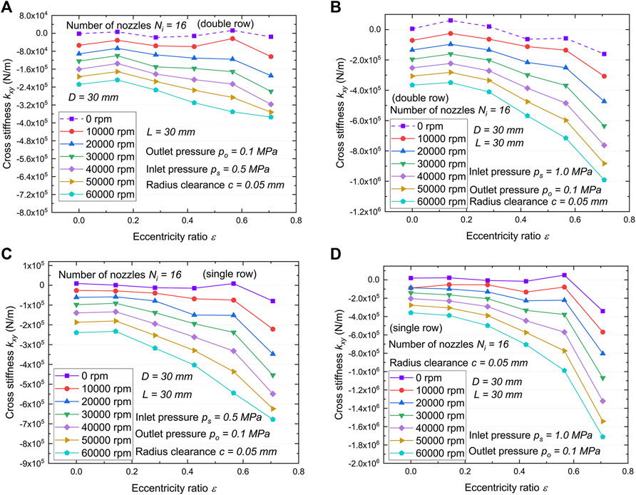
FIGURE 10. Variations of cross stiffness coefficient kxy with eccentricity ratio versus rotor speed. (A) Double row, ps = 0.5 MPa. (B) Double row, ps = 1.0 MPa. (C) Single row, ps =0.5 MPa. (D) Single row, ps =1.0 MPa.
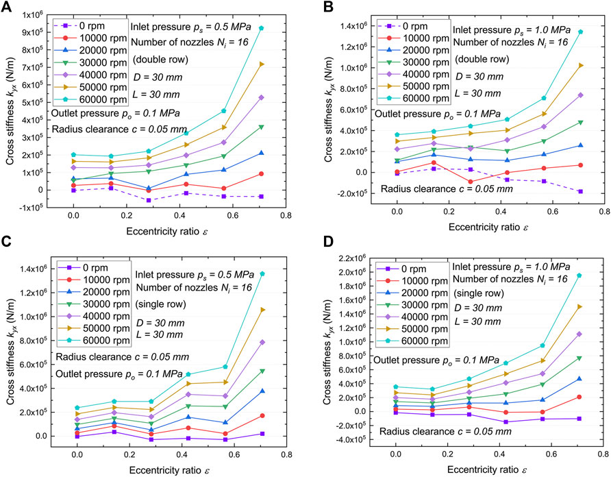
FIGURE 11. Variations of cross stiffness coefficient kyx with eccentricity ratio versus rotor speed. (A) Double row, ps = 0.5 MPa. (B) Double row, ps = 1.0 MPa. (C) Single row, ps =0.5 MPa. (D) Single row, ps =1.0 MPa.
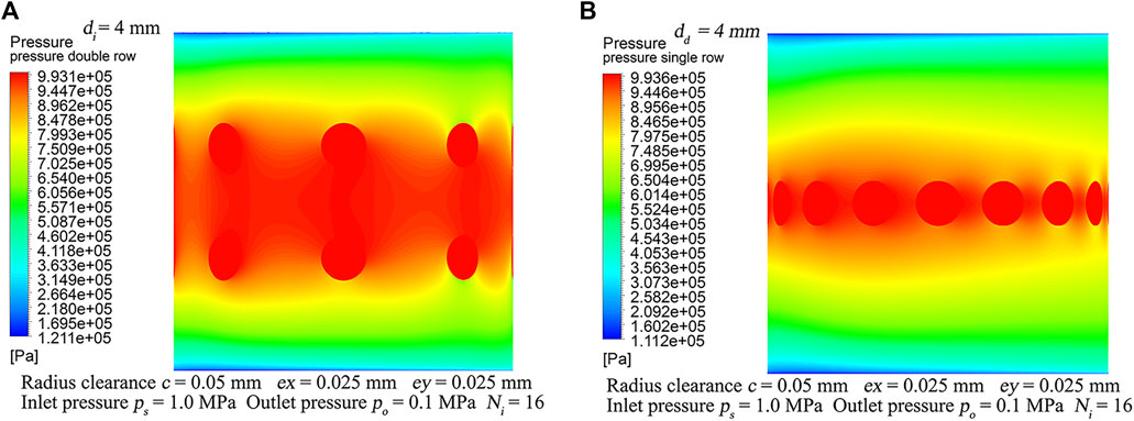
FIGURE 12. Gas film hydrodynamic and static pressure coupling fields, ex = 25
Journal speed and eccentricity independent force coefficients are important because they contribute less indetermination to the prediction of dynamic response of turbine rotor systems. Moreover, cross-coupled terms with different signs and negative direct force coefficients in nearly all cases imply that the system is not stable or potentially destabilizing. The coupling of hydrodynamic effects may add energy to the rotor-bearing system, giving shaft rise to whirl in the direction of journal rotation, while the coupling of static pressure from the nozzle affects only the whirl orbit shape without enhancing the energy of the system. One of the purposes of the double-row and single-row nozzle configuration cases is to demonstrate the significance of hydrodynamic pressure effect in the gas film. The self-excitation effect at higher operating speeds is increased in view of the stiffening effect occurring in the CO2 film, which leads to increased reaction forces during rotor vibration in a squeezed region. In order to prevent promoting rotor whirl as hydrodynamic pressure effect was increased, it is necessary to select appropriate nozzle layout or take additional precautions.
The bump foil combined cooler can be considered to provide an additional compensation for journal eccentricity. As shown in the model in Figure 13, the cooler would then follow the eccentricity of the rotor by means of the deformation of the bump foil (See (Gad and Kaneko, 2016). for a full description on the computation of force coefficients for foil structures). Dry-friction between the bump foil and the cooler and between the bump foil and the housing inner surface provides energy dissipation damping well in excess of that obtained in the limited viscous friction of CO2. Yet the full potential of utilizing the foil’s elastic deformation might be hindered by increasing asymmetry of the structural stiffness in the X- and Y-directions with increasing gas film force. Proper selection of the bump foil parameters is vital to exploiting the potential compensation for eccentricity. The ongoing research strives to address the eccentricity and frequency dependent properties of the force coefficient of cooler to eventually provide a cooling system that meets the temperature requirements of conventional bearings and dry gas seals in the SCO2 turbine rotor system at high-temperature and speed.
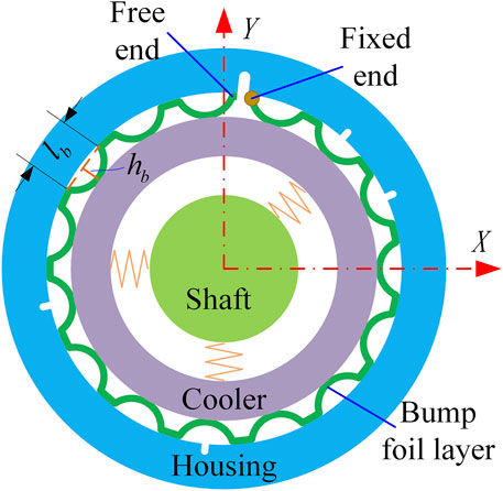
FIGURE 13. Schematic view of typical cooler in bump-type.
Conclusion
The proposed air-film cooling device on the turboshaft is intended for application in a 300 kW SCO2 turbomachine to provide reliable thermal management while coping with the hydrodynamic pressure effects of the gas film. Dynamic force coefficients and heat transfer performance of the cooling device with a radius clearance of 50 microns are presented. Then, the present work investigated the comprehensive effect of nozzle arrangement and inlet pressure variation on the heat transfer performance of gas film. From the investigation, it can be concluded as follows:
1) CFD results shows a significant increase of cooling efficiency (also refers to mass flow utilization) with increase of the mass flow rate at a cooling pressure of less than 0.7 MPa, and then shows a gradual decay trend. Heat transfer capacity of the cooler are affected by nozzle arrangement at a given mass flow rate, that is, the temperature difference at the nozzle position directly determines the heat dissipation capacity. The fluid density and velocity in the radial clearance were selected as factors affecting heat transfer to be studied. Heat transfer performance is enhanced in terms of average Nusselt number by increasing average density in the radial clearance at a given inlet pressure. However, the correlation with the average velocity of the fluid in the clearance is not very manifest.
2) The average Nusselt number of the interface with double-row nozzle configuration is significantly higher than that of the single-row case. However, due to the asymmetry of the temperature distribution, the single-row arrangement has higher heat transfer efficiency for the turbine shaft. The cooling device with a single row nozzles operating at lower inlet pressures will have a higher mass flow utilization efficiency.
3) Gas film stiffness showed journal speed and eccentricity dependency, and the absolute value of the cross-coupling stiffness coefficient is higher at high frequencies and large eccentricity ratios. Cross-coupled terms generally have an explicit variation tendency than direct terms. The absolute value of results shows that the direct term have the opposite trend with eccentricity ratio, while the variation trend of the cross term with that is the same. In general, as the journal eccentricity ratio increases, the force coefficients, except for kxx, increase accordingly. As the rotor speed increases, the absolute values of the cross stiffness and the direct stiffness kyy increase, but the term of kxx decreases.
Data Availability Statement
The raw data supporting the conclusions of this article will be made available by the authors, without undue reservation.
Author Contributions
JL mainly completes numerical simulation, experiment and paper writing HG and ZG provided the structural layout of the SCO turbine and the design of the cooling device. JsL directs the design and experiment of the testing machine. LL and YX completed the air film stiffness analysis.
Funding
This work is supported by the Special Project of Industrial Cluster in National Innovation Demonstration Zone (No. 201200210400) and the Program of Henan Center for Outstanding Overseas Scientists (No. GZS2018005).
Conflict of Interest
The authors declare that the research was conducted in the absence of any commercial or financial relationships that could be construed as a potential conflict of interest.
Publisher’s Note
All claims expressed in this article are solely those of the authors and do not necessarily represent those of their affiliated organizations, or those of the publisher, the editors and the reviewers. Any product that may be evaluated in this article, or claim that may be made by its manufacturer, is not guaranteed or endorsed by the publisher.
Acknowledgments
The authors would like to acknowledge the support from Henan Key Laboratory for Machinery Design and Transmission System. The authors wish to acknowledge also the turbine structure and guidance provided by the team of the University of Queensland, Australia.
References
Adeoye, S., Parahovnik, A., and Peles, Y. (2021). A Micro Impinging Jet with Supercritical Carbon Dioxide. Int. J. Heat Mass Transfer 170, 14. doi:10.1016/j.ijheatmasstransfer.2021.121028
Afroz, F., and Sharif, M. a. R. (2020). Numerical Investigation of Heat Transfer from a Plane Surface Due to Turbulent Annular Swirling Jet Impingement. Int. J. Therm. Sci. 151. doi:10.1016/j.ijthermalsci.2019.106257
Ahmadi, M. H., Alhuyi Nazari, M., Ghasempour, R., Pourfayaz, F., Rahimzadeh, M., and Ming, T. (2018). A Review on Solar‐assisted Gas Turbines. Energy Sci Eng 6 (6), 658–674. doi:10.1002/ese3.238
Ahmed, A., Wright, E., Abdel-Aziz, F., and Yan, Y. Y. (2021). Numerical Investigation of Heat Transfer and Flow Characteristics of a Double-wall Cooling Structure: Reverse Circular Jet Impingement. Appl. Therm. Eng. 189, 9. doi:10.1016/j.applthermaleng.2021.116720
Ahn, Y., Bae, S. J., Kim, M., Cho, S. K., Baik, S., Lee, J. I., et al. (2015). Review of Supercritical Co2 Power Cycle Technology and Current Status of Research and Development. Nucl. Eng. Tech. 47 (6), 647–661. doi:10.1016/j.net.2015.06.009
Alawadhi, K., Alfalah, A., Bader, B., Alhouli, Y., and Murad, A. (2021). An Optimization Study to Evaluate the Impact of the Supercritical CO2 Brayton Cycle's Components on its Overall Performance. Appl. Sciences-Basel 11 (5), 17. doi:10.3390/app11052389
Alotaibi, H. M., El Hassan, M., Assoum, H. H., Meraim, K. A., and Sakout, A. (2020). A Review Paper on Heat Transfer and Flow Dynamics in Subsonic Circular Jets Impinging on Rotating Disk. Energ. Rep. 6, 834–842. doi:10.1016/j.egyr.2020.11.124
Arslan, F., and Guzel, B. (2021). Numerical and Experimental Thermal-Hydraulic Performance Analysis of a Supercritical CO2 Brayton Cycle PCHE Recuperator. Arabian J. Sci. Eng. 14, 3. doi:10.1007/s13369-021-05464-3
Basumatary, K. K., Kumar, G., Kalita, K., and Kakoty, S. K. (2020). Stability Analysis of Rigid Rotors Supported by Gas Foil Bearings Coupled with Electromagnetic Actuators. Proc. Inst. Mech. Eng. C: J. Mech. Eng. Sci. 234 (2), 427–443. doi:10.1177/0954406219877903
Ehsan, M. M., Duniam, S., Li, J., Guan, Z., Gurgenci, H., and Klimenko, A. (2019). "A Comprehensive thermal Assessment of Dry Cooled Supercritical CO2 Power Cycles," in Applied Thermal Engineering. Langford Lane, Kidlington, Oxford, England: Pergamon-Elsevier Science Ltdthe Boulevard, 166. doi:10.1016/J.Applthermaleng.2019.114645
Feng, K., Li, W., Deng, Z., and Zhang, M. (2017). Thermohydrodynamic Analysis and Thermal Management of Spherical Spiral Groove Gas Bearings. Tribology Trans. 60 (4), 629–644. doi:10.1080/10402004.2016.1195467
Fp, I., Dp, D., and Tl, B. (2010). Fundamentals of Heat and Mass Transfer. New York, Inc: John Wiley & Sons.
Gad, A. M., and Kaneko, S. (2016). Tailoring of the Bearing Stiffness to Enhance the Performance of Gas-Lubricated Bump-type Foil Thrust Bearing. Proc. Inst. Mech. Eng. J: J. Eng. Tribology 230 (5), 541–560. doi:10.1177/1350650115606482
Han, D. J., Yang, J. F., Chen, C. T., and Tang, C. L. (2014). Experimental Research on the Dynamic Characteristics of Gas-Hybrid Bearing-Flexible Rotor System. J. Vibroengineering 16 (5), 2363–2374.
Ise, T., Imanishi, K., Asami, T., Tokumiya, T., Takada, N., Kimura, F., et al. (2014). Experimental Verification of Externally Pressurized Gas Journal Bearings with Asymmetric Gas Supply (Supply Gas Pressure Control Operation Using a Small Size Test Rig). J. Adv. Mech. Des. Syst. Manufacturing 8 (3), 11. doi:10.1299/jamdsm.2014jamdsm0029
Khatoon, S., Ishaque, S., and Kim, M. H. (2021). Modeling and Analysis of Air-Cooled Heat Exchanger Integrated with Supercritical Carbon Dioxide Recompression Brayton Cycle. Energ. Convers. Manag. 232, 16. doi:10.1016/j.enconman.2021.113895
Kim, S. H., Shin, H.-C., and Kim, S.-M. (2019). Numerical Study on Cooling Performance of Hybrid Micro-channel/micro-jet-impingement Heat Sink. J. Mech. Sci. Technol. 33 (7), 3555–3562. doi:10.1007/s12206-019-0649-7
Lapka, P., Cieplinski, A., and Rusowicz, A. (2020). Numerical Model and Analysis of Heat Transfer during Microjets Array Impingement. Energy 203, 9.
Lau, G. E., Mohammadpour, J., and Lee, A. (2021). Cooling Performance of an Impinging Synthetic Jet in a Microchannel with Nanofluids: An Eulerian Approach. Appl. Therm. Eng. 188, 19. doi:10.1016/j.applthermaleng.2021.116624
Lee, S., Yaganegi, G., Mee, D. J., Guan, Z. G., and Gurgenci, H. (2021). Part-load Performance Prediction Model for Supercritical CO2 Radial Inflow Turbines. Energ. Convers. Manag. 235, 11. doi:10.1016/j.enconman.2021.113964
Li, J., Gurgenci, H., Li, J. S., Li, L., Guan, Z. Q., and Yang, F. (2021). Optimal Design to Control Rotor Shaft Vibrations and thermal Management on a Supercritical CO2 Microturbine. Mech. Industry 22, 15. doi:10.1051/meca/2021023
Lubieniecki, M., Roemer, J., Martowicz, A., Wojciechowski, K., and Uhl, T. (2016). A Multi-Point Measurement Method for Thermal Characterization of Foil Bearings Using Customized Thermocouples. J. Elec Materi 45 (3), 1473–1477. doi:10.1007/s11664-015-4082-0
Maghrabie, H. M. (2021). Heat Transfer Intensification of Jet Impingement Using Exciting Jets - A Comprehensive Review. Renew. Sust. Energ. Rev. 139, 30. doi:10.1016/j.rser.2020.110684
Marchionni, M., Bianchi, G., and Tassou, S. A. (2021). Transient Analysis and Control of a Heat to Power Conversion Unit Based on a Simple Regenerative Supercritical CO2 Joule-Brayton Cycle. Appl. Therm. Eng. 183, 16. doi:10.1016/j.applthermaleng.2020.116214
Martowicz, A., Roemer, J., Lubieniecki, M., Zywica, G., and Baginski, P. (2020). Experimental and Numerical Study on the thermal Control Strategy for a Gas Foil Bearing Enhanced with Thermoelectric Modules. Mech. Syst. Signal Process. 138, 15. doi:10.1016/j.ymssp.2019.106581
Marzec, K. (2020). Influence of Jet Position on Local Heat Transfer Distribution under an Array of Impinging Nozzles with Non-planar Contour of the Cooled Surface. Heat Transfer Eng. 42, 1506–1521. doi:10.1080/01457632.2020.1800280
Menter, F. R. (1994). Influence of Free Stream Values on Turbulence Models for Engineering Applications. AIAA J. 30 (6), 1651–1659.
Modak, M., Sahu, S. K., and Park, H. S. (2021). An Experimental Study on Heat Transfer of Different Aqueous Surfactant Solutions Horizontal Impinging Jet Using Infrared Thermography. Appl. Therm. Eng. 188, 19. doi:10.1016/j.applthermaleng.2021.116668
Moore, J. J., Lerche, A., Allison, T., Ransom, D. L., and Lubell, D. (2011). Development of a High Speed Gas Bearing Test Rig to Measure Rotordynamic Force Coefficients. J. Eng. Gas Turbines Power-Transactions Asme 133 (10), 9. doi:10.1115/1.4002865
Pandey, V., Kumar, P., and Dutta, P. (2020). Thermo-hydraulic Analysis of Compact Heat Exchanger for a Simple Recuperated sCO(2) Brayton Cycle. Renew. Sust. Energ. Rev. 134, 21. doi:10.1016/j.rser.2020.110091
Patil, V. A., and Narayanan, V. (2005). Spatially Resolved Heat Transfer Rates in an Impinging Circular Microscale Jet. Microscale thermophysical Eng. 9 (2), 183–197. doi:10.1080/10893950590945058
Penkuhn, M., and Tsatsaronis, G. (2020). Systematic Evaluation of Efficiency Improvement Options for sCO(2) Brayton Cycles. Energy 210, 11. doi:10.1016/j.energy.2020.118476
Persico, G., Gaetani, P., Romei, A., Toni, L., Bellobuono, E. F., and Valente, R. (2021). Implications of Phase Change on the Aerodynamics of Centrifugal Compressors for Supercritical Carbon Dioxide Applications. J. Eng. Gas Turbines Power-Transactions Asme 143 (4), 11. doi:10.1115/1.4049924
Ryu, K. (2012). Prediction of Axial and Circumferential Flow Conditions in a High Temperature Foil Bearing with Axial Cooling Flow. J. Eng. Gas Turbines Power-Transactions Asme 134 (9), 6. doi:10.1115/1.4006841
San Andres, L., Ryu, K., and Kim, T. H. (2011a). Thermal Management and Rotordynamic Performance of a Hot Rotor-Gas Foil Bearings System-Part I: Measurements. J. Eng. Gas Turbines Power-Transactions Asme 133 (6). doi:10.1115/1.4001826
San Andres, L., Ryu, K., and Kim, T. H. (2011b). Thermal Management and Rotordynamic Performance of a Hot Rotor-Gas Foil Bearings System-Part II: Predictions versus Test Data. J. Eng. Gas Turbines Power-Transactions Asme 133 (6), 8. doi:10.1115/1.4001827
Siah Chehreh Ghadikolaei, S. (2021). Solar Photovoltaic Cells Performance Improvement by Cooling Technology: An Overall Review. Int. J. Hydrogen Energ. 46 (18), 10939–10972. doi:10.1016/j.ijhydene.2020.12.164
Tepe, A. Ü. (2021). Numerical Investigation of a Novel Jet Hole Design for Staggered Array Jet Impingement Cooling on a Semicircular Concave Surface. Int. J. Therm. Sci. 162. doi:10.1016/j.ijthermalsci.2020.106792
Tepea, A. Ü., Uysalb, Ü., Yetişkenc, Y., and Arslan, K. (2020). Jet Impingement Cooling on a Rib-Roughened Surface Using Extended Jet Holes. Appl. Therm. Eng. 178. doi:10.1016/j.applthermaleng.2020.115601
Turchi, C. S., Ma, Z. W., Neises, T. W., and Wagner, M. J. (2013). Thermodynamic Study of Advanced Supercritical Carbon Dioxide Power Cycles for Concentrating Solar Power Systems. J. Solar Energ. Engineering-Transactions Asme 135 (4), 7. doi:10.1115/1.4024030
White, M. T., Bianchi, G., Chai, L., Tassou, S. A., and Sayma, A. I. (2021). Review of Supercritical CO2 Technologies and Systems for Power Generation. Appl. Therm. Eng. 185, 28. doi:10.1016/j.applthermaleng.2020.116447
Zhang, B., Qi, S., Feng, S., Geng, H., Sun, Y., and Yu, L. (2018). An Experimental Investigation of a Microturbine Simulated Rotor Supported on Multileaf Gas Foil Bearings with Backing Bump Foils. Proc. Inst. Mech. Eng. Part J: J. Eng. Tribology 232 (9), 1169–1180. doi:10.1177/1350650117725463
Zhang, Y., Hei, D., Lü, Y., Wang, Q., and Müller, N. (2014). Bifurcation and Chaos Analysis of Nonlinear Rotor System with Axial-Grooved Gas-Lubricated Journal Bearing Support. Chin. J. Mech. Eng. 27 (2), 358–368. doi:10.3901/cjme.2014.02.358
Keywords: shaft cooling, gas film stiffness, heat transfer, cooler, jet impingement
Citation: Li J, Gurgenci H, Guan Z, Li J, Xue Y and Li L (2022) Thermal Management and Dynamic Performance of a Cooler Design for the Supercritical CO2 Turbine Shaft Cooling. Front. Energy Res. 10:839898. doi: 10.3389/fenrg.2022.839898
Received: 20 December 2021; Accepted: 14 March 2022;
Published: 25 April 2022.
Edited by:
Mostafa S. Shadloo, Institut national des sciences appliquées de Rouen, FranceReviewed by:
Fubin Yang, Beijing University of Technology, ChinaJie Gao, Harbin Engineering University, China
Copyright © 2022 Li, Gurgenci, Guan, Li, Xue and Li. This is an open-access article distributed under the terms of the Creative Commons Attribution License (CC BY). The use, distribution or reproduction in other forums is permitted, provided the original author(s) and the copyright owner(s) are credited and that the original publication in this journal is cited, in accordance with accepted academic practice. No use, distribution or reproduction is permitted which does not comply with these terms.
*Correspondence: Jishun Li, bGlfamlzaHVuQDE2My5jb20=