- 1Department of Mechanical Engineering, Kermanshah Branch of Islamic Azad University, Kermanshah, Iran
- 2Renewable Energy Research Department, Niroo Research Institute (NRI), Tehran, Iran
In the manufacturing process of solid oxide fuel cells (SOFCs), the residual stresses and curvature are developed in components due to the differences in material properties of cell layers. Residual stress may lead to the crack formation in the cell layers and facilitates cell fracture. In this work, the changes of the residual stress in the electrolyte layer of the anode-supported planar solid oxide fuel cells are experimentally determined at room temperature. The “sin2ψ” technique of X-ray diffraction method is employed to measure the residual stress in the half-cell samples. Investigation on the changes of the residual stress and curvature state in the scaling-up process of the cell is crucial for commercial use. Therefore, several cells with different sizes and shapes are investigated to evaluate the potential impact of cell size and cell shape on the residual thermal stress. Values of about −610 MPa are determined for the electrolyte layer on an oxidized ∼400 μm thick anode substrate. The results reveal that despite the effect of size and shape on the radius of curvature, these parameters have no significant impact on the residual stress level.
1 Introduction
A solid oxide fuel cell (SOFC) is a high-efficient electrochemical device that directly converts the chemical energy of fuels such as hydrogen and natural gas into electrical energy. In various configurations and designs, anode-supported planar SOFCs are widely used due to their higher power density and lower manufacturing cost (Ettler et al., 2010; Fan et al., 2014; Du et al., 2018; Shin et al., 2020; Padinjarethil et al., 2021).
Residual stresses are developed during the manufacturing process of the cells due to the thermo-elastic mismatch between the cell layers (Selçuk et al., 2001; He et al., 2011; Molla et al., 2013; Wei et al., 2018; Shang et al., 2019; Frandsen et al., 2021). These residual stresses can result in performance degradation (Li et al., 2020; Liu et al., 2021) as a result of delamination (Selçuk et al., 2001) or the formation of cracks in the cell layers (Selçuk et al., 2001; Ettler et al., 2010; Li et al., 2010) and in the extreme case may lead to the complete deterioration of the cell (Steinbrech, 2008; Zhang et al., 2008; Villanova et al., 2010).
In the case of the anode-supported cells, much attention has been paid to the residual stress distribution after the cell fabrication process at room temperature and/or during its high-temperature operation, especially in the electrolyte and anode layers. It should be noted that because of low stiffness and low thickness of cathode in the anode-supported cells, the cathode layer has little effect on the stresses in the other components (Sun et al., 2009; He et al., 2011).
Figure 1 shows a schematic cross-section of the residual stress distribution in an anode-supported cell at room temperature. The stress is compressive within the electrolyte layer, and its value does not change significantly through the electrolyte thickness. The anode experiences tensile stress towards the electrolyte and compressive stress towards its free surface. The stress level at the free surface is lower than that of at the interface (Severson and Assadi, 2013; Xiang et al., 2014; Wei et al., 2018).
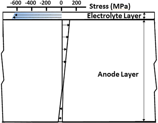
FIGURE 1. Schematic diagram of the cross-sectional view of the residual stress distribution in an anode supported cell at room temperature.
For conventional anode (Ni/YSZ) and electrolyte (YSZ) materials, depending on the fabrication procedure and cell design, the maximum compressive stress in the electrolyte is as high as 500–700 MPa (Yakabe et al., 2004; Fischer et al., 2005; Laurencin et al., 2008; Zhang et al., 2008; Malzbender et al., 2009; Severson and Assadi, 2013; Xiang et al., 2014; Wei et al., 2018). The maximum tensile and compressive stresses in the anode are respectively about 20–100 MPa and 10–50 MPa (Laurencin et al., 2008; Zhang et al., 2008; Severson and Assadi, 2013; Greco et al., 2014; Xiang et al., 2014; Wei et al., 2018).
Figure 2 shows a similar trend for residual stress distribution in an anode-supported cell at operating temperature of 800°C. However, the operating temperature reduces the absolute stress level by about 50% (Fischer et al., 2005; Laurencin et al., 2008; Xiang et al., 2014) or even higher (Frandsen et al., 2021).
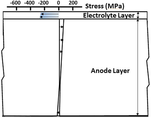
FIGURE 2. Decrease in overall residual stress level at working temperature (compare with Figure 1).
During cell operation, chemical stresses (e.g., redox and chemical expansion) and thermally induced stresses are also superimposed to the residual stresses. These stresses are the primary cause of the failure of the cell (Kakaç et al., 2007; Delette et al., 2012) and should not exceed the strength of the materials (Fischer et al., 2005; Malzbender and Steinbrech, 2007; Malzbender et al., 2008, Malzbender et al., 2009). Since the residual stress significantly affects the magnitude and distribution of stresses in the cell at operating conditions (Clague et al., 2012), estimation of residual stress at room temperature would be beneficial to calculate the stress in the anode-supported cells under operating conditions (Yakabe et al., 2004; Zhang et al., 2008; Lin et al., 2009).
The effects of various factors such as layers thickness, using an additional layer, applying different additives, sintering temperature, cell configurations and fabrication method on the residual stress of anode supported cells have been studied by researchers.
Zhang et al. (2008) developed an analytical model to predict the residual thermal stresses in a single solid oxide fuel cell. They investigated the influence of the thickness of each layer on the residual stress distributions in the cell. In a similar study, Fan et al. (2014) calculated the relationship between the residual stresses and the thicknesses of different cell components when the cell is cooled down to the room temperature. Laurencin et al. (2008) proposed a numerical model to study the risk of cell failure due to residual stresses and investigated the effect of electrolyte thickness on the risk of anode failure. Severson and Assadi (2013) developed a structural model to analyze residual stresses in anode- and electrolyte-supported planar SOFCs and they studied residual stress distribution for different thickness combinations.
Malzbender et al. (2006) showed that applying an additional layer, as a support for the anode layer, compensates the cell curvature. However, the average residual tensile stress in the anode increases, which could lead to a more significant fracture probability of the anode layer. Sun et al. (2009) compared the effect of thermal cycling on residual stress and distortion in a standard 3-layer cell and one with an additional layer. Charlas et al. (2015) analyzed and discussed the influence of an additional layer on the residual stresses in 4 layers half-cells.
He et al. (2011) showed that adding Al2O3 in NiO–YSZ support materials affected the thermal expansion mismatch and reduced the residual stress in the cell. Cologna et al. (2010) tailored the electrolyte composition by adding a fraction of fine powders to coarse powders to reduce the sintering stresses.
Yakabe et al. (2004) studied the effect of sintering temperature on the calculated residual stress in the electrolyte at room temperature with X-ray measurements. Malzbender et al. (2008) determined residual stress of half-cells with oxidized anode as a function of temperature.
Fujita et al. (2011) and Somekawa et al. (2013) estimated and compared residual stresses in the electrolytes of segmented-in-series solid oxide fuel cells (SIS-SOFCs) and usual anode-supported cells at room temperature by X-ray diffraction. Nakajo et al. (2011) used a model based on the Euler–Bernoulli theory to study the residual stresses in the cell layers. Using the temperature-dependent mechanical properties of materials has enabled the study of the residual stress in several anode-supported SOFC configurations. Menzler et al. (2014) developed a novel route to fabricate anode-supported solid oxide fuel cells, and they measured the residual stresses in the electrolyte after sintering, before and after flattening. The stress level is significantly reduced compared to the data obtained for half-cells manufactured via the classical route.
Fischer et al. (2005) showed that the flattening procedure of the SOFCs to remove the warp, essentially does not change the residual stress level; however, it reduces the in-plane fluctuation. Moon et al. (2011) concluded that applying compressive force during co-firing can affect the residual stress distribution. The co-fired cell under optimal pressure showed homogeneous stress distribution. Shin et al. (2020) showed that the roll calendaring process could produce cells with lower and more uniform residual stress than the conventional uniaxial press.
Many researchers have developed equations for calculating the residual stress and radius of curvature during the sintering process based on fundamental stress-strain relations (Lee et al., 2004; Malzbender et al., 2006; Chang et al., 2008; Cologna et al., 2010; Xiang et al., 2014). Using these equations, the impact of different parameters on residual stress and radius of curvature were investigated, including layer thickness, cell configuration, sintering temperature, and material properties. These equations do not consider the dimensions and geometry of cells and implicitly assume that the size and geometry do not affect residual stress and radius of curvature.
However, some experiments showed that the dimension and geometry of cells affect the radius of curvature. Aguilar-Arias et al. (2013) showed that the increase in cell diameter increases the radius of curvature. Converting deflection data of Moon et al. (2011) and Orui et al. (2008) into the radius of curvature demonstrated that the radius of curvature increases with increasing dimension. Mücke et al. (2009) showed that the radius of curvature of the horizontally sintered specimens is three times higher than the free-hanging samples. This difference is attributed to the effect of gravity and the weight of the samples. Molla et al. (2013) presented an improved model that effect of the weight of the sample (gravity) on the kinetics of distortion is considered. Even under identical conditions, large cells are received more force due to the gravity effect. Malzbender (2010) also investigated the effect of cell geometry on the curvature radius of cells.
On the other hand, the commercial cells are usually much larger than the samples made in the laboratories or used in the research experiments. So, while researchers use small-size cells to conduct preliminary studies on the effect of various parameters on cell performance, it is still necessary to enlarge the cell size for practical and commercial use. Any changes of the residual stress and curvature state in this scaling-up process should be investigated. Regarding the effect of dimension on the radius of curvature and the relationship between curvature and residual stress, we experimentally investigated the potential effects of the shape and size of ceramic cells on the residual stress.
In this work, we report our evaluation of the residual stresses in the electrolyte of anode-supported solid oxide fuel cells, which reveals the effect of the shape and size of cell on residual stresses. All cells have been fabricated by the conventional tape casting and co-sintering method. The conditions of the co-firing and tape-casting processes were identical for all specimens. We used the X-ray diffraction method to measure the residual stresses in the electrolyte of the anode-supported cell. This technique has been widely used to evaluate the residual and thermal stress in solid oxide fuel cells (Yakabe et al., 2004; Fischer et al., 2005; Sumi et al., 2006; Malzbender et al., 2009; Huang and Harter, 2010; Yang et al., 2013; Wei et al., 2018).
2 Materials and Methods
2.1 Sample Preparation
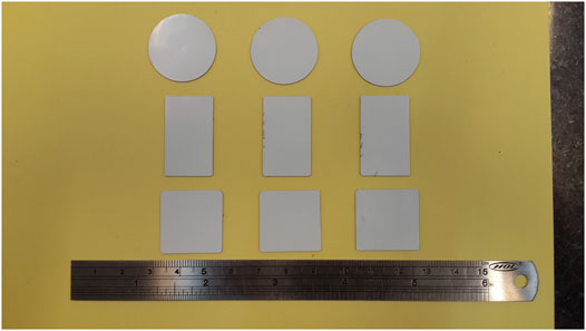
Commercial 8YSZ (FCM, United States) powder with a surface area of 6.7 m2 gr−1 and NiO-YSZ cermet powder (FCM, United States) with a surface area of 2.4 m2 gr−1 were used for the fabrication of the electrolyte and the anode layers, respectively. The electrolyte slurry was cast on a Si-coated Mylar sheet using a homemade tape caster. After drying, the anode slurry was cast on the electrolyte layer. Dried green half-cell was cut into suitable geometries to acquire the desired sizes and shapes after sintering. Figure 3 shows the small half-cells after this step. Further experimental details of the fabrication process are described in previous works (Azari et al., 2015; Azari et al., 2016).
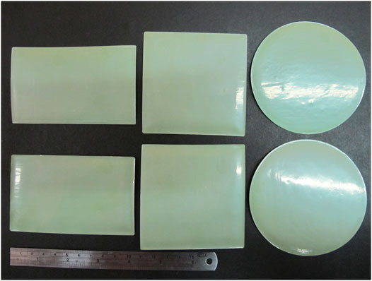
Burn out process was performed at 1000°C for 2 h in air atmosphere. After the burn-out procedure, for obtaining the desirable mechanical properties, pre-sintered half-cells were sintered at 1400°C for 4 h in air atmosphere. Figure 4 displays the large half-cells after this step.
Anode and electrolyte thicknesses of all samples are about 400 μm and 30 μm, respectively. The open porosity of the sintered anode was measured by the Archimedes method using distilled water as the immersion medium. The open porosity of the anode was 14.4 Vol% to total anode volume. Specifications of nine fabricated half cells are shown in Table 1.
2.2 Residual Stress Measurement
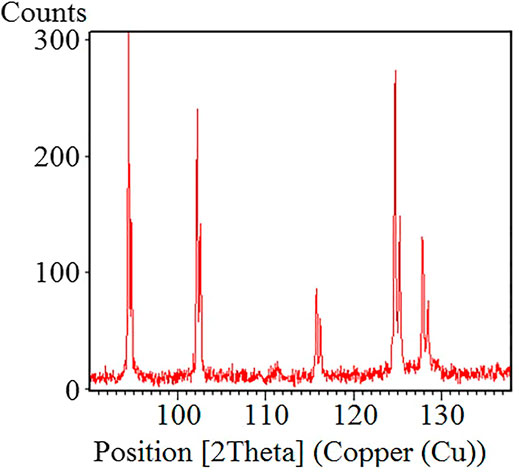
The residual stresses in the electrolyte of the anode-supported half cells were estimated using an X-ray Philips X’Pert diffractometer. The conventional sin2ψ method and iso-inclination technique were used, and the Cu-Kα X-ray source was selected. In this method, a diffraction peak at a high 2θ angle is used because, in this case, applying a large ψ range is possible. (Yakabe et al., 2004). For this purpose, a preliminary scan was first conducted from 90 to 140° (2θ), which is displayed in Figure 5. Based on the results of the initial scan, the reflection plane (5 3 1) was selected. The diffraction angle 2θ is about 125°.
The residual stresses in the electrolyte were estimated using the following equation (Yakabe et al., 2004; Fujita et al., 2011):
where d0 is the interplanar spacing under a stress-free condition, ψ the tilt angle, E is Young’s modulus of 215 GPa, and υ is Poisson’s ratio of 0.3 (Fischer et al., 2005; Fujita et al., 2011; Menzler et al., 2014).
The stress was evaluated assuming a plane unidirectional stress field. Diffraction measurements were taken at 9 ψ-angles (negative and positive inclinations) at equal distances in sin2ψ from 0 to 0.5, using a step of Δθ = 0.05° in the neighborhood of 125°.
3 Results and Discussion
3.1 Effect of Cell Shape on the Residual Stress
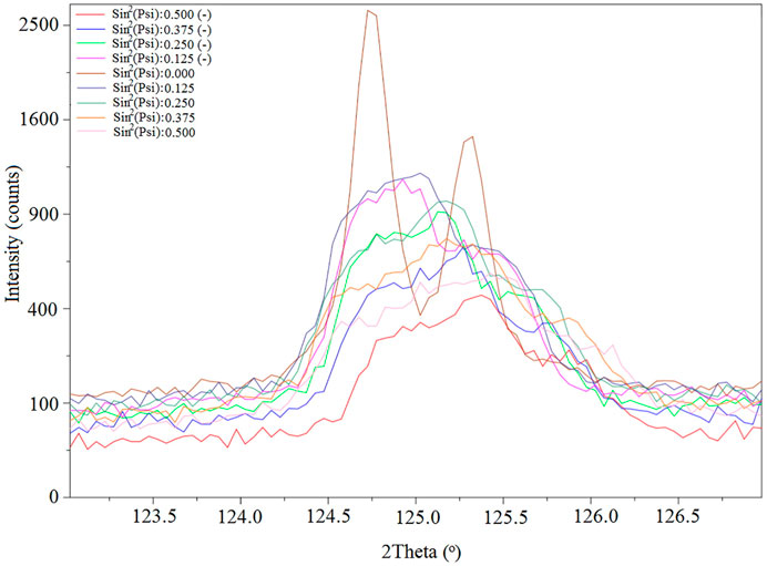
The shift of the diffracted (5 3 1) peak of YSZ with the change of ψ for the sample c3 is illustrated in Figure 6. For all samples, the peak position shifted to a higher angle with increasing ψ.
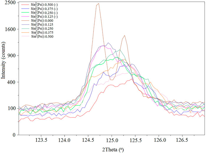
FIGURE 6. Change of the diffraction peak of YSZ (5 3 0) plane with the change of ψ for the sample c3.
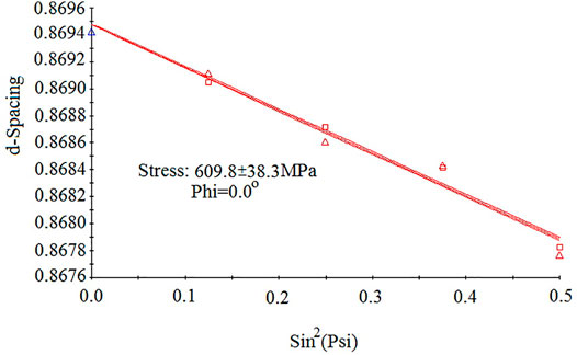
For all samples, the corresponding d-spacing of various tilt angles ψ were determined from the detected YSZ (5 3 1) diffraction peak positions. Figure 7 shows the d–sin2ψ diagram for sample c3. As seen, the d-spacing decreases with the increase of sin2ψ, implying that the residual stress is compressive in this specimen. The residual stresses are estimated from the d–sin2ψ diagram using Eq. 1.
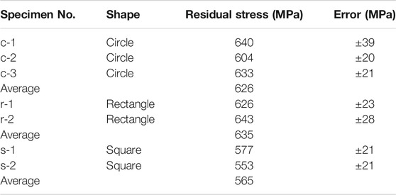
For small cells, the residual stresses in the electrolyte were calculated and listed in Table 2. The average value of 610 MPa was calculated for residual stress in the electrolyte layer in this work. It can be seen that the estimated values are in agreement with the values reported in the literature for similar anode-supported cells. Yakabe et al. (2004) reported 774 MPa for similar cells with anode and electrolyte thicknesses of 2000 μm and 30 μm, respectively. According to Yakabe simulation (Yakabe et al., 2004), a decrease of anode layer thickness from 2000 μm to 400 μm (with a constant electrolyte layer thickness of 30 μm) can reduce electrolyte stress level by about 150 MPa.
The results in Table 2 reveal that the shape of the cells has little effect on the residual stresses and can be ignored. This is not unexpected, because the main cause of the residual stress is the difference in the material properties of the layers, and any potential effect of other parameters should be studied.
It should be noted that all samples have been fabricated and sintered under identical conditions and all the effective parameters in the cell production route are the same. They are cut out of the same tape and sintered together in the furnace. However, the results of Table 2 also show that the samples with the same shape, have different residual stresses. This fluctuation in residual stress under the same experimental conditions has already been reported (Yakabe et al., 2004; Fischer et al., 2005; Sun et al., 2009; Fujita et al., 2011). Because, even under apparently identical conditions of the production process, microstructure may be inhomogeneous (e.g. density and distribution of the crack). Inhomogeneity in the microstructure of ceramic can affect the material properties, and properties of different regions would be different. For example, the thickness of the tape as an effective factor on the residual stress level is not equal in length of a tape.
Therefore, the X-ray technique is unable to precisely detect the residual stresses due to changes in the cell shape. Although the stress is lowest for square cells, by taking into account the intrinsic errors of the method and the errors generated by assumptions (i.e. plane unidirectional stress field), no absolute conclusion can be made. In other words, the conventional sin2ψ method cannot measure the probable effect of cell shape on the residual stresses.
3.2 Effect of Cell Size on the Residual Stress
The X-ray stress evaluation method was also used to study the effect of cell size on the residual stress. The XRD patterns for residual stress measurement of a large cell (C1) are shown in Figure 8.
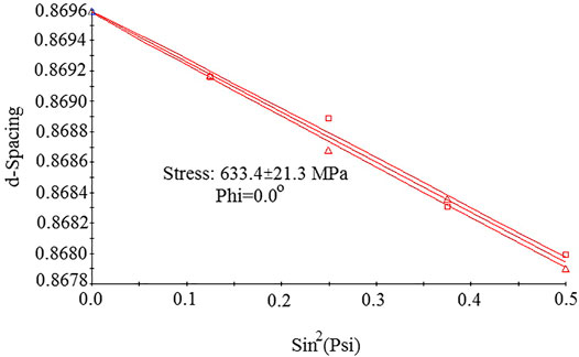
Figure 9 shows the d–sin2ψ diagram for sample C1. The estimated residual stress in the electrolyte was compressive stress of 610 MPa for sample C1 and 618 MPa for sample C2.
Comparing this result for large cells with small cells data (Table 2) shows that the residual stress is independent of the cell size. This is also consistent with the previous simulations for anode-supported cells (Yakabe et al., 2004). Simulation results reported by Yakabe and co-workers (Yakabe et al., 2004) show that when the cell size is larger than 5 mm, the calculated stress is almost independent of the cell size.
Results of this section revealed that scaling up the cell size does not affect the residual stress state. However, this does not mean that scaling up the cells to larger sizes does not affect the probability of cell fracture. Because the increase in cell size is associated with the statistical probability of larger defects which can decrease the fracture stress of large cells in comparison with smaller specimens in an identical residual stress state (Fischer et al., 2005).
On the other hand, due to the mismatch between the material properties of the individual layers, residual stresses and warpage are evolved during the manufacturing process. Some modifications, such as using additives or the decrease of sintering temperature, can reduce both residual stress and warpage (Yakabe et al., 2004; He et al., 2011; Menzler et al., 2014). Some modifications, such as using a compensation layer, can reduce warpage, but increases residual stress (Malzbender et al., 2006). Our results demonstrate that despite the effect of cell size on the warpage behavior, cell size does not affect residual stress.
4 Conclusion
Using large-scale SOFCs is very crucial for practical and commercial use. Changes in the residual stress and curvature state in the scaling up process of cells should be investigated. This work was an effort to address the stress state in the electrolyte layer of the anode-supported planar solid oxide fuel cell. The residual stress of the YSZ electrolyte was evaluated using the X-ray sin2 ψ stress measurement method. The changes in the residual stress were measured to investigate the impact of cell size and cell shape on the residual stress.
The XRD measurements were carried out at room temperature in the electrolyte of half-cells. In the case of a ∼30 μm thick electrolyte layer on an oxidized ∼400 μm thick anode substrate, the estimated residual stresses in the electrolyte were compressive stresses of around 600 MPa. For our specimens, the change of cell shape without changing other parameters did not alter the stress states and the relative distributions. Regarding the intrinsic errors of the method and the errors generated by assumptions, the probable effect of shape is not large enough to be detected by the conventional sin2ψ method.
It was also found that the residual stress in the electrolyte of the anode-supported planar SOFC remained almost constant during the scale-up process, and the change of cell size did not affect the residual stress level.
Based on the results of this study, it can be concluded that despite the effect of size and shape on the radius of curvature, these parameters do not affect the residual stress level.
Data Availability Statement
The raw data supporting the conclusions of this article will be made available by the authors, without undue reservation.
Author Contributions
KA: Conceptualization, methodology, experimental tests, writing—original draft, writing—review and editing, funding acquisition HA: Conceptualization, investigation, writing—review and editing MT: Investigation, experimental tests, writing—review and editing SB: Investigation, writing—review and editing.
Funding
This work was financially supported by the Kermanshah Branch of Islamic Azad University under a research program entitled “Survey of Residual Stress in Solid Oxide Fuel Cells”.
Conflict of Interest
The authors declare that the research was conducted in the absence of any commercial or financial relationships that could be construed as a potential conflict of interest.
Publisher’s Note
All claims expressed in this article are solely those of the authors and do not necessarily represent those of their affiliated organizations, or those of the publisher, the editors and the reviewers. Any product that may be evaluated in this article, or claim that may be made by its manufacturer, is not guaranteed or endorsed by the publisher.
References
Aguilar-Arias, J., Hotza, D., Lenormand, P., and Ansart, F. (2013). Planar Solid Oxide Fuel Cells Using PSZ, Processed by Sequential Aqueous Tape Casting and Constrained Sintering. J. Am. Ceram. Soc. 96, 3075–3083. doi:10.1111/jace.12559
Azari, K., Vaghasloo, Y. A., Mohandesi, J. A., and Ghobadzadeh, A. H. (2015). The Effect of Cell Shape on the Warpage in Solid Oxide Fuel Cells. J. Power Sourc. 279, 64–71. doi:10.1016/j.jpowsour.2014.12.147
Azari, K., Mohandesi, J. A., and Vaghasloo, Y. A. (2016). Size Dependence of Warpage in Solid Oxide Fuel Cell. J. Power Sourc. 301, 326–331. doi:10.1016/j.jpowsour.2015.10.016
Chang, J., Guillon, O., Rödel, J., and Kang, S.-J. L. (2008). Characterization of Warpage Behaviour of Gd-Doped ceria/NiO-Yttria Stabilized Zirconia Bi-layer Samples for Solid Oxide Fuel Cell Application. J. Power Sourc. 185, 759–764. doi:10.1016/j.jpowsour.2008.07.075
Charlas, B., Frandsen, H. L., Brodersen, K., Henriksen, P. V., and Chen, M. (2015). Residual Stresses and Strength of Multilayer Tape Cast Solid Oxide Fuel and Electrolysis Half-Cells. J. Power Sourc. 288, 243–252. doi:10.1016/j.jpowsour.2015.04.105
Clague, R., Marquis, A. J., and Brandon, N. P. (2012). Finite Element and Analytical Stress Analysis of a Solid Oxide Fuel Cell. J. Power Sourc. 210, 224–232. doi:10.1016/j.jpowsour.2012.03.027
Cologna, M., Sglavo, V. M., and Bertoldi, M. (2010). Sintering and Deformation of Solid Oxide Fuel Cells Produced by Sequential Tape Casting. Int. J. Appl. Ceram. Technol. 7, 803–813. doi:10.1111/j.1744-7402.2009.02390.x
Delette, G., Laurencin, J., Murer, S., and Leguillon, D. (2012). Effect of Residual Stresses on the Propagation of Interface Cracks between Dissimilar Brittle Materials: Contribution of Two and Three-Dimensional Analyses. Eur. J. Mech. - A/Solids 35, 97–110. doi:10.1016/j.euromechsol.2012.02.001
Du, Y., Hedayat, N., Panthi, D., Ilkhani, H., Emley, B. J., and Woodson, T. (2018). Freeze-casting for the Fabrication of Solid Oxide Fuel Cells: A Review. Materialia 1, 198–210. doi:10.1016/j.mtla.2018.07.005
Ettler, M., Timmermann, H., Malzbender, J., Weber, A., and Menzler, N. H. (2010). Durability of Ni Anodes during Reoxidation Cycles. J. Power Sourc. 195, 5452–5467. doi:10.1016/j.jpowsour.2010.03.049
Fan, P., Li, G., Zeng, Y., and Zhang, X. (2014). Numerical Study on thermal Stresses of a Planar Solid Oxide Fuel Cell. Int. J. Therm. Sci. 77, 1–10. doi:10.1016/j.ijthermalsci.2013.10.008
Fischer, W., Malzbender, J., Blass, G., and Steinbrech, R. W. (2005). Residual Stresses in Planar Solid Oxide Fuel Cells. J. Power Sourc. 150, 73–77. doi:10.1016/j.jpowsour.2005.02.014
Frandsen, H. L., Chatzichristodoulou, C., Charlas, B., Kiebach, R., Kwok, K., Norby, P., et al. (2021). Fast Relaxation of Stresses in Solid Oxide Cells through Reduction. Part I: Macro-Stresses in the Cell Layers. Int. J. Hydrogen Energ. 46, 1548–1559. doi:10.1016/j.ijhydene.2020.10.145
Fujita, K., Somekawa, T., Hatae, T., and Matsuzaki, Y. (2011). Residual Stress and Redox Cycling of Segmented-In-Series Solid Oxide Fuel Cells. J. Power Sourc. 196, 9022–9026. doi:10.1016/j.jpowsour.2011.01.022
Greco, F., Frandsen, H. L., Nakajo, A., Madsen, M. F., and Van herle, J. (2014). Modelling the Impact of Creep on the Probability of Failure of a Solid Oxide Fuel Cell Stack. J. Eur. Ceram. Soc. 34, 2695–2704. doi:10.1016/j.jeurceramsoc.2013.12.055
He, C. R., Wang, W. G., Wang, J., and Xue, Y. (2011). Effect of Alumina on the Curvature, Young's Modulus, thermal Expansion Coefficient and Residual Stress of Planar Solid Oxide Fuel Cells. J. Power Sourc. 196, 7639–7644. doi:10.1016/j.jpowsour.2011.05.025
Huang, K., and Harter, H. D. (2010). Temperature-dependent Residual Stresses in Plasma Sprayed Electrolyte Thin-Film on the Cathode Substrate of a Solid Oxide Fuel Cell. Solid State Ionics 181, 943–946. doi:10.1016/j.ssi.2010.05.008
Kakaç, S., Pramuanjaroenkij, A., and Zhou, X. (2007). A Review of Numerical Modeling of Solid Oxide Fuel Cells. Int. J. Hydrogen Energ. 32, 761–786. doi:10.1016/j.ijhydene.2006.11.028
Laurencin, J., Delette, G., Lefebvre-joud, F., and Dupeux, M. (2008). A Numerical Tool to Estimate SOFC Mechanical Degradation: Case of the Planar Cell Configuration. J. Eur. Ceram. Soc. 28, 1857–1869. doi:10.1016/j.jeurceramsoc.2007.12.025
Lee, S. H., Messing, G. L., and Green, D. J. (2004). Warpage Evolution of Screen Printed Multilayer Ceramics during Co-firing. Key Eng. Mater. 264-268, 321–330. doi:10.4028/www.scientific.net/kem.264-268.321
Li, F., Pan, J., Guillon, O., and Cocks, A. (2010). Predicting Sintering Deformation of Ceramic Film Constrained by Rigid Substrate Using Anisotropic Constitutive Law. Acta Materialia 58, 5980–5988. doi:10.1016/j.actamat.2010.07.015
Li, Q., Cao, G., Zhang, X., and Li, G. (2020). Topology Optimization of the Microstructure of Solid Oxide Fuel Cell Cathodes. Acta Materialia 201, 278–285. doi:10.1016/j.actamat.2020.10.003
Lin, C.-K., Huang, L.-H., Chiang, L.-K., and Chyou, Y.-P. (2009). Thermal Stress Analysis of Planar Solid Oxide Fuel Cell Stacks: Effects of Sealing Design. J. Power Sourc. 192, 515–524. doi:10.1016/j.jpowsour.2009.03.010
Liu, Z., Wang, B., and Cazorla, C. (2021). Mechanical and Electronic Properties of CeO2 under Uniaxial Tensile Loading: A DFT Study. Materialia 15, 101050. doi:10.1016/j.mtla.2021.101050
Malzbender, J. (2010). Curvature and Stresses for Bi-layer Functional Ceramic Materials. J. Eur. Ceram. Soc. 30, 3407–3413. doi:10.1016/j.jeurceramsoc.2010.07.036
Malzbender, J., and Steinbrech, R. W. (2007). Advanced Measurement Techniques to Characterize Thermo-Mechanical Aspects of Solid Oxide Fuel Cells. J. Power Sourc. 173, 60–67. doi:10.1016/j.jpowsour.2007.07.072
Malzbender, J., Fischer, W., and Steinbrech, R. W. (2008). Studies of Residual Stresses in Planar Solid Oxide Fuel Cells. J. Power Sourc. 182, 594–598. doi:10.1016/j.jpowsour.2008.04.035
Malzbender, J., Steinbrech, R. W., and Singheiser, L. (2009). A Review of Advanced Techniques for Characterising SOFC Behaviour. Fuel Cells 9, 785–793. doi:10.1002/fuce.200800110
Malzbender, J., and Steinbrech, R. W. (2008). Threshold Fracture Stress of Thin Ceramic Components. J. Eur. Ceram. Soc. 28, 247–252. doi:10.1016/j.jeurceramsoc.2007.05.017
Malzbender, J., Wakui, T., and Steinbrech, R. W. (2006). Curvature of Planar Solid Oxide Fuel Cells during Sealing and Cooling of Stacks. Fuel Cells 6, 123–129. doi:10.1002/fuce.200500109
Menzler, N. H., Malzbender, J., Schoderböck, P., Kauert, R., and Buchkremer, H. P. (2014). Sequential Tape Casting of Anode-Supported Solid Oxide Fuel Cells. Fuel Cells 14, 96–106. doi:10.1002/fuce.201300153
Molla, T. T., Frandsen, H. L., Bjørk, R., Ni, D. W., Olevsky, E., and Pryds, N. (2013). Modeling Kinetics of Distortion in Porous Bi-layered Structures. J. Eur. Ceram. Soc. 33, 1297–1305. doi:10.1016/j.jeurceramsoc.2012.12.019
Moon, H., Kang, D.-W., Park, H.-G., and Hyun, S.-H. (2011). Stress and Camber Analysis of Anode-Supported Electrolytes by Tape-Casting and Co-firing Techniques. Int. J. Hydrogen Energ. 36, 10991–10997. doi:10.1016/j.ijhydene.2011.05.097
Mücke, R., Menzler, N. H., Buchkremer, H. P., Stöver, D., Mücke, R., Menzler, N. H., et al. (2009). Cofiring of Thin Zirconia Films during SOFC Manufacturing. J. Am. Ceram. Soc. 92, S95–S102. doi:10.1111/j.1551-2916.2008.02707.x
Nakajo, a., Van Herle, J., and Favrat, D. (2011). Sensitivity of Stresses and Failure Mechanisms in SOFCs to the Mechanical Properties and Geometry of the Constitutive Layers. Fuel Cells 11, 537–552. doi:10.1002/fuce.201000108
Orui, H., Nozawa, K., Watanabe, K., Sugita, S., Chiba, R., Komatsu, T., et al. (2008). Development of Practical Size Anode-Supported Solid Oxide Fuel Cells with Multilayer Anode Structures. J. Electrochem. Soc. 155, B1110. doi:10.1149/1.2969942
Padinjarethil, A. K., Bianchi, F. R., Bosio, B., and Hagen, A. (2021). Electrochemical Characterization and Modelling of Anode and Electrolyte Supported Solid Oxide Fuel Cells. Front. Energ. Res. 9, 1–19. doi:10.3389/fenrg.2021.668964
Selçuk, a., Merere, G., and Atkinson, a. (2001). The Influence of Electrodes on the Strength of Planar Zirconia Solid Oxide Fuel Cells. J. Mater. Sci. 36, 1173–1182. doi:10.1023/A:1004833909780
Severson, H., and Assadi, M. (2013). Analysis of Residual and Operational Thermal Stresses in a Planar SOFC. J. Fuel Cel Sci. Technol. 10, 061001. doi:10.1115/1.4025051
Shang, S., Lu, Y., Cao, X., Song, X., Shi, M., and Wang, F. (2019). A Model for Oxidation-Induced Stress Analysis of Ni-Based Anode-Supported Planar Solid Oxide Fuel Cell. Int. J. Hydrogen Energ. 44, 16956–16964. doi:10.1016/j.ijhydene.2019.04.166
Shin, J., Park, J. H., Kim, J., Yoon, K. J., Son, J.-W., Lee, J.-H., et al. (2020). Suppression of Processing Defects in Large-Scale Anode of Planar Solid Oxide Fuel Cell via Multi-Layer Roll Calendering. J. Alloys Comp. 812, 152113–152117. doi:10.1016/j.jallcom.2019.152113
Somekawa, T., Fujita, K., and Matsuzaki, Y. (2013). Residual Stress Change with Time of a Segmented-In-Series Solid Oxide Fuel Cell Using an In Situ X-ray Stress Measuring Method. J. Power Sourc. 221, 64–69. doi:10.1016/j.jpowsour.2012.07.064
Sumi, H., Ukai, K., Yokoyama, M., Mizutani, Y., Doi, Y., Machiya, S., et al. (2006). Changes of Internal Stress in Solid-Oxide Fuel Cell during Red-Ox Cycle Evaluated by In Situ Measurement with Synchrotron Radiation. J. Fuel Cel Sci. Technol. 3, 68–74. doi:10.1115/1.2134739
Sun, B., Rudkin, R. A., and Atkinson, A. (2009). Effect of Thermal Cycling on Residual Stress and Curvature of Anode-Supported SOFCs. Fuel Cells 9, 805–813. doi:10.1002/fuce.200800133
Villanova, J., Sicardy, O., Fortunier, R., Micha, J.-S., and Bleuet, P. (2010). Determination of Global and Local Residual Stresses in SOFC by X-ray Diffraction. Nucl. Instr. Methods Phys. Res. Section B: Beam Interactions Mater. Atoms 268, 282–286. doi:10.1016/j.nimb.2009.09.017
Wei, J., Osipova, T., Malzbender, J., and Krüger, M. (2018). Mechanical Characterization of SOFC/SOEC Cells. Ceramics Int. 44, 11094–11100. doi:10.1016/j.ceramint.2018.03.103
Xiang, Z., Haibo, S., Fenghui, W., Kang, L., and Jianye, H. (2014). Curvature Reversal and Residual Stress in Solid Oxide Fuel Cell Induced by Chemical Shrinkage and Expansion. Fuel Cells 14, 1057–1061. doi:10.1002/fuce.201400050
Yakabe, H., Baba, Y., Sakurai, T., Satoh, M., Hirosawa, I., and Yoda, Y. (2004). Evaluation of Residual Stresses in a SOFC Stack. J. Power Sourc. 131, 278–284. doi:10.1016/j.jpowsour.2003.12.057
Yang, Y.-C., Lu, L.-Y., Hwang, C.-S., and Tsai, C.-H. (2013). Residual Stresses in the Atmospheric Plasma Sprayed NiO/LDC Anode of the Metallic Supported Solid Oxide Fuel Cells. Surf. Coat. Tech. 231, 193–200. doi:10.1016/j.surfcoat.2012.06.038
Keywords: solid oxide fuel cell, residual stress, radius of curvature, cell size, cell shape, X-ray diffraction
Citation: Azari K, Abdoli H, Torabi M and Bozorgmehri S (2022) Experimental Investigation on Potential Effect of Cell Shape and Size on the Residual Stress in Solid Oxide Fuel Cells. Front. Energy Res. 10:839673. doi: 10.3389/fenrg.2022.839673
Received: 20 December 2021; Accepted: 31 January 2022;
Published: 16 February 2022.
Edited by:
Jinliang Yuan, Ningbo University, ChinaReviewed by:
Chao Yang, Shanghai Maritime University, ChinaZhonggang Zhang, Jimei University, China
Hironori Nakajima, Kyushu University, Japan
Copyright © 2022 Azari, Abdoli, Torabi and Bozorgmehri. This is an open-access article distributed under the terms of the Creative Commons Attribution License (CC BY). The use, distribution or reproduction in other forums is permitted, provided the original author(s) and the copyright owner(s) are credited and that the original publication in this journal is cited, in accordance with accepted academic practice. No use, distribution or reproduction is permitted which does not comply with these terms.
*Correspondence: Khaled Azari, a2hhbGVkYXphcmlAaWF1a3NoLmFjLmly, a2hhbGVkYXphcmlAZ21haWwuY29t
 Khaled Azari
 Hamid Abdoli
 Morteza Torabi
 Shahriar Bozorgmehri