 H. D. Wang
 Y. L. Chen
 W. Villanueva
95% of researchers rate our articles as excellent or good
Learn more about the work of our research integrity team to safeguard the quality of each article we publish.
Find out more
ORIGINAL RESEARCH article
Front. Energy Res. , 14 February 2022
Sec. Nuclear Energy
Volume 10 - 2022 | https://doi.org/10.3389/fenrg.2022.839667
This article is part of the Research Topic Numerical Methods and Computational Sciences Applied to Nuclear Energy View all 12 articles
In a postulated severe accident, the thermo-mechanical loads from the corium debris that has relocated to the lower head of the reactor pressure vessel (RPV) can pose a credible threat to the RPV’s structural integrity. In case of a vessel breach, it is vital to predict the mode and timing of the vessel failure. This affects the ex-vessel accident progression and plays a critical role in the development of mitigation strategies. We propose a methodology to assess RPV failure based on MELCOR and ANSYS Mechanical APDL simulations. A Nordic-type boiling water reactor (BWR) is considered with two severe accident scenarios: i) SBO (Station Blackout) and ii) SBO + LOCA (Loss of Coolant Accident). In addition, the approach considers the dynamic ablation of the vessel wall due to a high-temperature debris bed with the use of the element kill function in ANSYS. The results indicate that the stress failure mechanism is the major cause of the RPV failure, compared to the strain failure mechanism. Moreover, the axial normal stress and circumferential normal stress make the dominant contributions to the equivalent stress
The Fukushima nuclear accident occurred in 2011, stemming from a strong earthquake and a subsequent tsunami that induced a station blackout (SBO) scenario (Naitoh et al., 2013a; Kaneko et al., 2015; Pellegrini et al., 2016). In this scenario, the nuclear power plants (NPPs) experienced serious damage due to the loss of off-site power, resulting in the leakage of large amount of radioactive material to the environment. The reactor pressure vessel (RPV) of a light water reactor is one of the key safety barriers that prevent the release of radioactive substances to the environment. Thus, analyses of RPV failure are warranted to provide insights into the reactor’s accident progression and develop effective mitigation strategies.
During a severe accident, molten core materials and internal structures, also known as corium, can relocate to the lower head of the RPV and form a debris bed. This debris bed can threaten the integrity of the RPV lower head with four possible failure modes: lower head global rupture, melt impingement and melt-through, penetration tube heats up and ruptures, and penetration tube ejection (Naitoh et al., 2013b; Herranz et al., 2015; Li et al., 2014; Mao et al., 2017; Yue et al., 2020; Willschütz et al., 2003; Siegele et al., 1999; Rempe et al., 1993). The structural behavior of the RPV is a complex phenomenon, including the macro-structural global deformation (i.e., the displacement of the RPV lower head) and the micro-structural stress-strain responses. From the global point of view, the failure deformation of the vessel lower head has not been explicitly characterized in the field of RPV structural integrity due to its different effects on various shapes and sizes of RPVs. So the deformation is commonly used as a supplementary in a specific RPV application (Mao et al., 2016a; Villanueva et al., 2012a) and a validation for the finite element analysis (FEA) (Sehgal et al., 2003; Devos et al., 1999). However, the material properties can be characterized by the tensile-creep tests under various temperatures and loadings, providing the limits of the stress and strain for certain carbon steel (Humphries and Chu, 2002). One can find that the stress and strain mechanisms are the major factors initiating the RPV failure, and the failure criterion based on the stress-strain response is widely implemented in the failure analysis of the RPV lower head (see Table 1 for examples) (Ikonen, 1999; Koundy et al., 2005; Villanueva et al., 2012b; Kaneko et al., 2015; Mao et al., 2016b; Mao et al., 2017). When the equivalent stress of the RPV lower head exceeds the material strength, RPV failure occurs. The creep strain also cannot be ignored because the vessel can undergo creep failure when the temperature exceeds a certain level for an extended period even at low pressures (Rempe et al., 1993; Callister and Rethwisch, 2011). In the present study, we pay particular attention to the failure mode and timing of a Nordic-type BWR vessel under the SBO and SBO + LOCA events from the perspective of micro-structural stress-strain responses, as well as considering its macro-structural global deformation. The heat exchange between the debris bed and the RPV wall is not constant; hence, the stress and the strain across the vessel wall behave in a transient way. To investigate the changing conditions of RPVs under accident scenarios, a one-way coupling method has been developed using MELCOR and ANSYS Mechanical APDL codes. By taking transient thermo-mechanical loadings as boundary conditions, the failure mechanism of the vessel lower head is investigated in detail, and its failure location and timing are also predicted for the worst scenarios (i.e., SBO and SBO + LOCA).
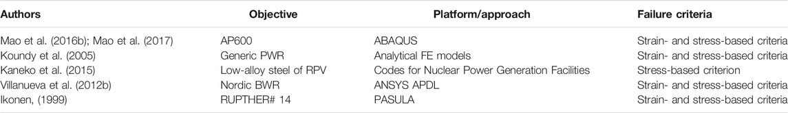
TABLE 1. Examples from the literature (Ikonen, 1999; Koundy et al., 2005; Villanueva et al., 2012b; Kaneko et al., 2015; Mao et al., 2016b; Mao et al., 2017) of strain- and stress-based failure criteria used in structural analysis of RPVs.
Since the temperature at the inner surface of the RPV may exceed the local melting of the vessel wall which can lead to an ablation of the wall, it is important to investigate the structural behavior of the RPV with an ablated profile. To simplify the calculation, the geometry of the ablated vessel wall is mostly assumed to be constant during the structural analysis in previous study (Sehgal et al., 2003; Wang et al., 2021). However, the temperature of the vessel wall has a gradient across the thickness and continues to increase due to the continuous heat transfer from the corium debris bed. This debris bed is expected to fill the ablated region in the wall and produce further ablation at the inner surface of the vessel wall (Zhan et al., 2018). Accordingly, the vessel wall becomes thinner and thinner as the accident progresses, which is supposed to be much weaker to withstand the certain loads than before (Matejovic et al., 2017). Thus, it is possibly accurate to take the change of vessel thickness into account when predicting the timing and mode of RPV failure. For that, the approach “element killing” is adopted in the structural analysis in the present study, updating the vessel profile regularly according to the transient temperature. The thermal and mechanical response of the RPV lower head is then investigated based on the dynamic ablation of the vessel wall.
Considering the strengths of MELCOR in modeling accident progression and ANSYS in simulating the structural behavior, the thermo-mechanical analysis is developed based on these two tools. The structural analysis of RPV was implemented in ANSYS while the thermal loads and mechanical loads (i.e., the applied boundary conditions on the RPV in ANSYS) from the debris bed were calculated using MELCOR. In the following sections, the procedure is outlined for this thermo-mechanical analysis, and descriptions of modeling in MELCOR and the Finite Element (FE) model in ANSYS APDL are also presented.
MELCOR, as an integral code for severe accidents in an NPP, includes various models or packages [e.g., Core (COR) Package, Decay Heat (DCH) Package, and Cavity (CAV) Package]. These packages can simulate a variety of severe accident phenomena in a severe accident, such as core degradation, fission product release, and hydrodynamics. However, some of these models or packages are simplified to ensure a computationally efficient simulation (Dietrich et al., 2015; Humphries et al., 2017). In this case, some other codes and approaches are adapted to a specific phenomenon in a severe accident, whose roles are complementary to those of MELCOR (Amidu et al., 2021a; Amidu et al., 2021b). In this work, the first aim is to investigate the vessel state (e.g., the stress and the strain) during the Severe Accident (SA), and the second task is to assess the timing and location of RPV failure. In terms of the failure analysis of the RPV lower head, MELCOR has two failure modes (i.e., creep failure based on a life-fractional rule and the yield stress failure criterion), with a description of the failure time and location of RPV failure in the form of an output text file. Thus, detailed information on the structural response of the RPV lower head is limited. In contrast, ANSYS allows users to perform detailed nonlinear analyses using the Finite Element Method (FEM). The FEM can divide the RPV lower head into a finite number of subdomains, addressing the constitutive behavior in each subdomain and recombining them into a global system for the final calculation. This method allows ANSYS to provide more information than just the timing and location of RPV failure for the whole transient calculation. Both global deformation and the stress-strain responses at different locations of the vessel can be accessed for the entire accident progression, which are also important in the assessment of severe accidents and accident mitigation strategies (Humphries and Chu, 2002).
In assessing the structural integrity of the RPV, it is necessary to set up failure criteria. One can take the yield stress or ultimate stress as the stress-based criterion in engineering practice. Compared to the yield stress failure criterion, the ultimate stress failure criterion is a more popular application of RPV failure (Humphries and Chu, 2002; Koundy et al., 2008; Kaneko et al., 2015; Villanueva et al., 2020). This criterion assumes that the structural failure is determined by the material necking. In addition, the strain-based failure criteria are also considered in the present thermo-mechanical analysis because the RPV can undergo strain failure at an elevated temperature even under moderate stresses (Rempe et al., 1993; Callister and Rethwisch, 2011; Villanueva et al., 2012b). That is, we declare RPV failure if any one of the following is satisfied: 1) the von Mises stress exceeds the ultimate stress, 2) creep strain exceeds 20%, or 3) total strain exceeds 25% (Rempe et al., 1993; Wang et al., 2021).
Figure 1 shows the general framework of this research. Given that the occurrence of RPV failure will lead to the release of corium from the RPV to the cavity in MELCOR simulation, we deactivated the failure modes first to simulate the SBO progression, thereby obtaining the thermo-mechanical loads during a longer period. Then these loads are transferred as the boundary conditions for the transient structural analysis with ANSYS, further investigating the behavior of the vessel and predicting its failure time and location based on the failure criteria mentioned above. Also, the accident scenario (i.e., SBO accident or SBO + LOCA accident) with the same conditions was simulated again in MELCOR with the failure modes, and some information about RPV failure can be given using the MELCOR platform. By comparing the timing and location of RPV failure predicted by these two codes, respectively, some insights into the failure analysis on the vessel lower head are provided in the succeeding section.
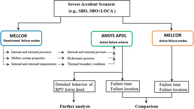
FIGURE 1. Framework of thermo-mechanical analysis for a Nordic BWR with SBO and SBO + LOCA scenarios.
The SBO and SBO + LOCA scenarios were assumed to occur in a Nordic BWR with a 3,000 MWth nominal power (Pershagen, 1996). The major parameters of the Nordic BWR and settings in MELCOR are summarized in Table 2. The severe accident strategy employed by the Nordic BWR is cavity flooding, which is also considered in the MELCOR simulation. This accident strategy is assumed to activate when the water level in the vessel is below a critical value.
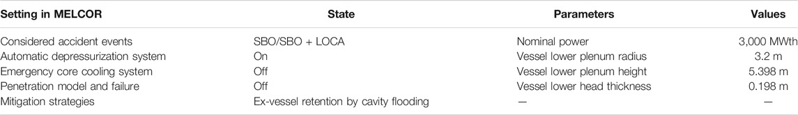
TABLE 2. Major parameters and settings of the Nordic BWR in MELCOR.
In MELCOR, the thermal-hydraulic response of this reactor was calculated by means of modeling its nodalization (see Figure 2A). Figures 2B,C show the mesh configuration for the COR package nodalization, which is used to simulate the degradation and relocation of the core in the RPV. As indicated in Figure 2B, there are 28 uneven segments along the vessel lower plenum and 21 rings in the radial direction. These radial rings are depicted by various cells and colors, as shown in Figure 2C, representing different fuel assemblies and ring groups, respectively.
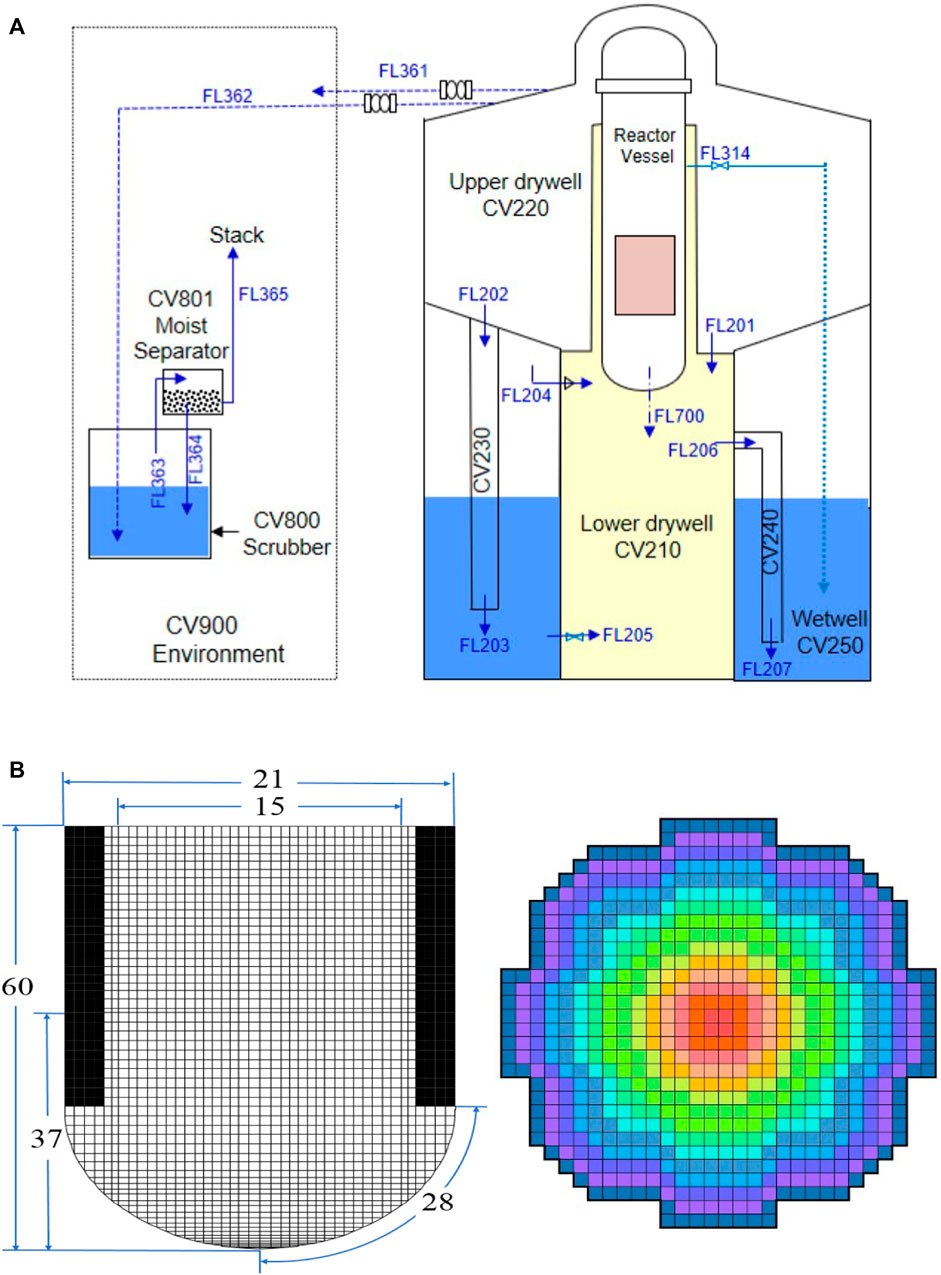
FIGURE 2. (A) Schematic of the containment nodalization of a Nordic BWR, (B) fine nodalization in the COR package of MELCOR, and (C) group of fuel assemblies for radial rings (Chen et al., 2019).
The numerical simulation of the RPV was performed in a 2D axisymmetric geometry as shown in Figure 3. As stated above, the output data from MELCOR (e.g., internal and external surface temperatures of the vessel, internal and external pressures, and the molten corium properties) were transferred as loads and constraints on the RPV for the structural analysis using ANSYS.
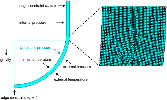
FIGURE 3. 2D axisymmetric geometry of the ablated RPV, loads, constraints, and the mesh.
Furthermore, the temperature of the vessel wall has a gradient across the thickness and continues to increase due to the continuous heat transfer from the debris bed. This debris bed is expected to fill the ablated region in the wall and produce further ablation at the inner surface of the vessel wall (Zhan et al., 2018). Here, the thermal and mechanical response of the RPV lower head is investigated based on a dynamic ablation process of the vessel wall. First, the RPV geometry is modeled in ANSYS Mechanical APDL with an initial thickness of 0.198 m. Then the “element killing” method is implemented in ANSYS to simulate the dynamic state of vessel ablation, updating the ablated profile of the RPV regularly based on the temperature distribution. In addition, a sufficiently fine mesh (40 element layers across the vessel wall) with a characteristic length of 0.005 m is considered, which is necessary to describe the detailed profile during the ablation process (see Figure 3).
The material properties of SA533B1 are considered and adopted from the study by (Rempe et al., 1993), which are all temperature-dependent, including the density, thermal conductivity, specific heat capacity, ultimate strength, coefficient of thermal expansion, and modulus of elasticity. Since most of these data are limited at temperatures of up to 1373K in the reference, a constant-valued extrapolation of the material properties of SA533B1 is used for temperatures above 1373K.
The maximum temperature on the surface of the RPV is beyond the melting point of the vessel material. It is well known that creep occurs when the temperature is higher than 0.3–0.4 times the melting temperature of the material (Gandy, 2007). To account for the creep effect, a modified time hardening model is used and is given by the following:
where
In addition to the creep behavior, the elasto-plastic behavior of this material is governed by a nonlinear isotropic (NISO) hardening model (see Eq. 2). The detailed values of the parameters and validations of these two models are given in the study by (Wang et al., 2021).
where
In this section, some observations are briefly given for the case with deactivated failure modes in MELCOR, as mentioned previously in the framework (see Figure 1). The main events of accident progression are listed in Table 3.
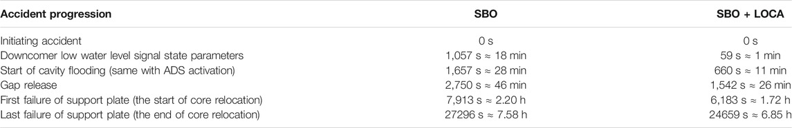
TABLE 3. Accident progression for the case with deactivated failure modes in MELCOR.
It should be noted that these output data from MELCOR are used as the input conditions for the detailed structural analysis using ANSYS Mechanical. In Figure 4A, the total mass accumulated in the lower head is provided for both SBO and SBO + LOCA cases. The initial mass comprises intact supporting structures and penetration guide tubes. The abrupt increase happens earlier in the SBO + LOCA case, before 2 h, but both follow the same trend after 3 h onward and stabilize around 280 tons after 6 h.
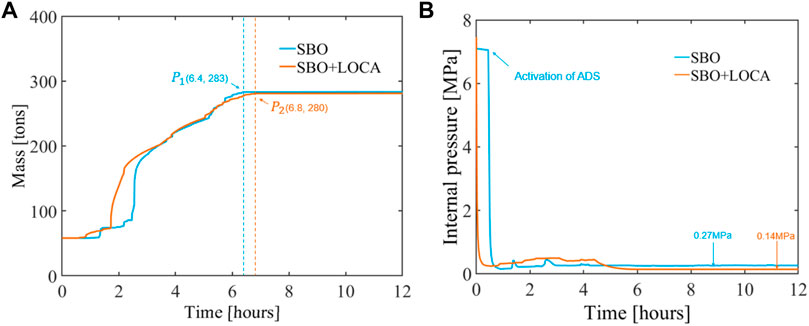
FIGURE 4. (A) Evolution of total mass in the RPV lower head under SBO and SBO + LOCA scenarios. The total mass stabilizes at
Figure 4B shows the internal pressure evolution of the RPV at the first 12 h. For the SBO case (marked in blue line), the automatic depressurization system (ADS) is active at about half an hour, and the internal pressure before that is maintained at the level of 7 MPa due to the operation of safety relief valves. Subsequently, it dramatically reduces at 0.27 MPa and stabilizes. For the SBO + LOCA case, the vessel pressure decreases dramatically at the very beginning of the accident due to rapid steam release to the containment through the initial break at the main steam line. The ADS system has no effect in this case. The pressure stabilizes at around 0.14 MPa.
Figures 5A,B show the internal temperature evolution for the SBO and SBO + LOCA cases. A significant decrease in temperatures is shown at t = 0.5 h for the SBO case in conjunction with activation of the ADS (see Figure 5A). An earlier decrease in temperatures is also shown for the SBO + LOCA case due to the main steam line break (see Figure 5B). For both SBO and SBO + LOCA cases, segments 19–21 (marked with solid lines in both figures) show higher internal temperatures at the late stage and reach the melting temperature earlier than other segments, at 1789K at 5.88 h and 6.05 h, respectively. Given these data from MELCOR, the temperature of each segment is used as the boundary condition for the vessel surface with a different range of polar angles in the structural analysis (see Table 4).
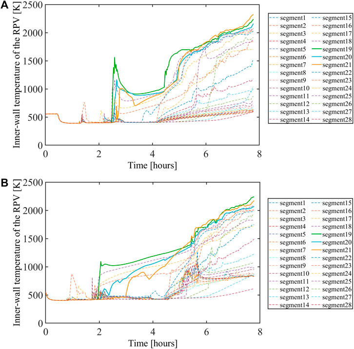
FIGURE 5. Evolution of (A) the inner-wall temperature of the RPV in the SBO case and (B) the inner-wall temperature of the RPV in the SBO + LOCA case.
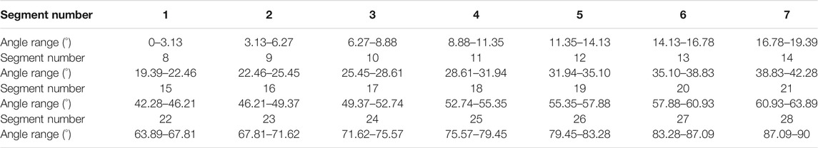
TABLE 4. Range of polar angles for each segment in the MELCOR model.
Compared with the SBO case, the steam line breach in SBO + LOCA can accelerate the coolant vaporization and take away some heat (Chen et al., 2019). Accordingly, the results showed significant difference for these two cases from the corium mass, internal pressure, and temperature to the time of melt-through, as well as the external pressure and temperature (not shown). The effect of these differences on the behavior of the RPV is investigated from the structural analyses in the following sections.
The RPV undergoes an ablation caused by the thermal load from the debris bed, and hence, the thickness of the vessel wall changes during the accident progression. In MELCOR, the residual thickness profile is determined by the inner-wall temperatures, resulting from the debris temperature distribution and heat fluxes directed into the vessel wall. As for the determination of the vessel ablated profile in ANSYS, these inner-wall temperatures as a function of time are directly used as the thermal boundary condition imposed on the vessel wall, deactivating the elements with zero stiffness when its temperature is higher than the melting point of this material (i.e., the element killing method). Here, the ablated profile of the RPV is updated regularly by eliminating the elements when their corresponding temperature exceeded 1789K, which is the melting point of material SA533B1 (Rempe et al., 1993).
Figures 6, 7 show the dynamic process of RPVs’ ablation and temperature distribution and their corresponding times. As expected, the ablation of the vessel wall occurs approximately after t = 6 h for both SBO and SBO + LOCA and becomes worse as time progresses. These severe ablations are concentrated on the upper surface of the RPV lower head, and eventually, a melt-though on the vessel wall happens after 7.22 h for the SBO case and 7.33 h for the SBO + LOCA case.
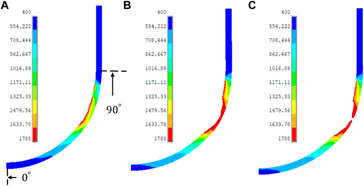
FIGURE 6. Dynamic ablation for the SBO case: temperature distribution (K) at time (A) t = 6 h, (B) t = 7.16, and (C) t = 7.22 h.
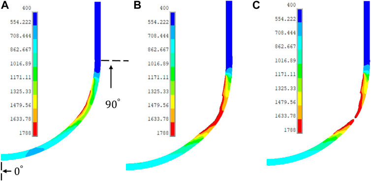
FIGURE 7. Dynamic ablation for the SBO + LOCA case: temperature distribution (K) at time (A) t = 6 h, (B) t = 7.16, and (C) t = 7.33 h.
Figure 8 shows a sequence of five snapshots illustrating the ablation process; these snapshots are obtained by describing the residual thickness at interval
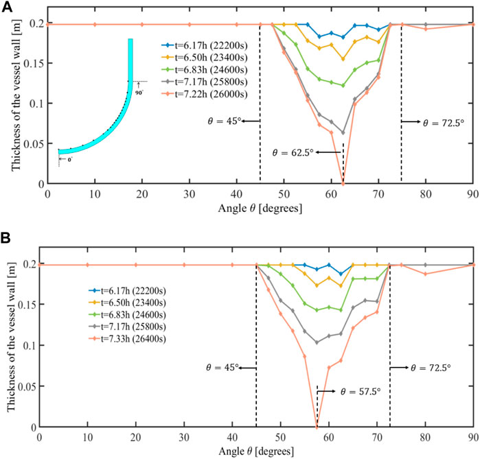
FIGURE 8. Thickness of the RPV lower head at t = 6.17 h, t = 6.50 h, t = 6.83 h, t = 7.17 h, and t = 7.22h/7.33 h (the time of melt-through) for (A) SBO and (B) SBO + LOCA cases.
As the accident progresses, the stresses and strains of the vessel wall change in time and are both strongly dependent on the temperature. To illustrate the complex and nonlinear behavior of the RPV, we present snapshots of the stress and strain responses of the RPV during the ablation.
The results of temperature, von Mises stress, and creep strain of the vessel wall for the SBO case at t = 7.16 h are shown in Figure 9. In Figure 9A, the highly ablated area corresponds to the region with higher temperature, where the creep strain is also larger (see Figure 9C). However, it is found that the von Mises stress is lower in these regions due to the significant yielding in the regions with high temperature (see Figure 9B). Since the thermo-mechanical response of the vessel wall is quite complex, we took three locations on the vessel wall to further investigate the vessel behavior. They correspond to the high-creep strain (region A at angle
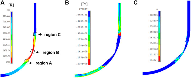
FIGURE 9. (A) Temperature distribution (K), (B) von Mises stress distribution (Pa), and (C) creep strain distribution of the vessel wall at time = 7.16 h for the SBO case.
Figure 10 gives the comparison of von Mises stress of the vessel (the solid lines) and SA533B1 ultimate stress (the dotted lines) at the critical regions. It can be seen in Figures 10A,B that the stresses at region A remain below the ultimate stress of the vessel steel until t = 7.3 h. The results of region B are depicted in Figure 10C with a zoomed-in plot in Figure 10D, which shows that the von Mises stress at the outer wall exceeds the ultimate stress of the steel at t = 6.8 h and the inner wall thereafter. Compared to the other two segments, region C has the highest stress after 6 h (see Figure 10E). However, a larger safety margin between the vessel stress and the stress limit can be seen in this region. This is because the ultimate stress is temperature-dependent, and hence, the stress limit of region C is relatively high due to its low local temperature.
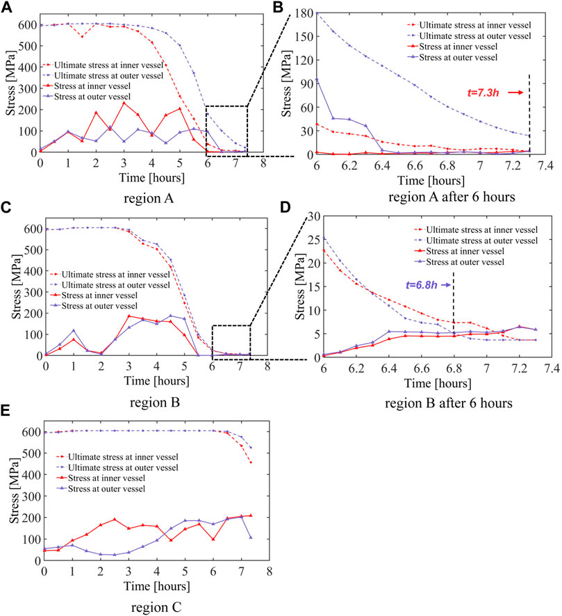
FIGURE 10. Comparison of von Mises stress of the vessel and SA533B1 ultimate stress at the critical regions for the SBO case; (A) region A, (B) zoomed-in version of region A after 6 h, (C) region B, (D) zoomed-in version of region B after 6 h, and (E) region C.
As mentioned before, the RPV failure mechanism includes the stress and strain responses according to the two failure criteria in Framework of the Thermo-Mechanical Analysis. From Figure 10, it was found that RPV failure occurs at 6.8 h in region B when considering the stress limit of the vessel steel. To check whether there is a strain failure before the stress failure, snapshots of creep and total strains at t = 6.8 h are shown in Figure 11. The maximum creep strain and maximum total strain have values of 9% and 9.1%, respectively, located at the region with high ablation. Both are sufficiently below the limits set in the strain-based failure criteria (i.e., 20% creep strain and 25% total strain). Accordingly, RPV failure for the SBO case at 6.8 h is due to the stress failure mechanism. In addition, the failure location is in region B (angle
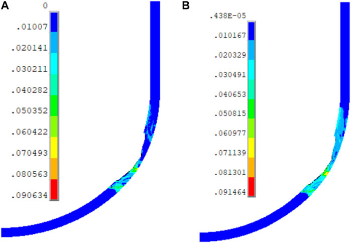
FIGURE 11. (A) Equivalent creep strain and (B) total strain of the vessel wall at time = 6.8 h for the SBO case.
Next, we present the structural analysis of the RPV with the SBO + LOCA case, similar to the SBO case. Figure 12 shows the results of temperature, von Mises stress, and creep strain of the vessel wall for the SBO + LOCA case at t = 7.16 h. Like the SBO case, the highly ablated area shows higher temperature, higher creep strain, and higher stress. Given the distribution of the stresses along the vessel wall, it can be noted that high stresses are in the same region as in the SBO case, that is, in region C at angle 83°–87°, while high-creep and high-temperature values occur at the thinnest region of the RPV lower head, that is, in region B* at angle 55°–58°. Note that region B* in Figure 12 and region B in Figure 9 are at different angles, but both correspond to the regions with high ablation for the SBO + LOCA and SBO cases, respectively.
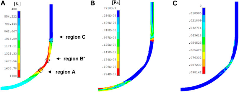
FIGURE 12. (A) Temperature distribution (K), (B) von Mises stress distribution (Pa), and (C) creep strain distribution of the vessel wall at time = 7.16 h for the SBO + LOCA case.
Next, a comparison of von Mises stress of the vessel and the SA533B1 ultimate stress at the critical regions (see Figure 12) is shown to investigate the timing and region of RPV failure in the SBO + LOCA case. It can be observed that the von Mises stresses do not exceed the allowable stress for the given temperature at region A and region C (not shown here). However, as temperature is quite high in region B*, the stress limit of this region (specifically the outer part of the vessel) is reached at t = 7.1 h (see Figure 13A, B).
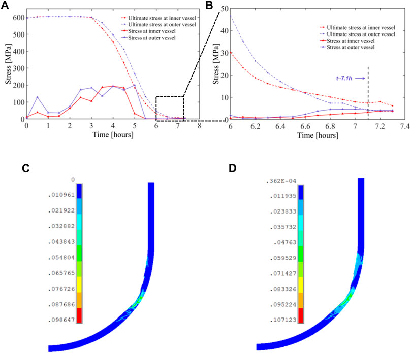
FIGURE 13. Comparison of von Mises stress of the vessel and SA533B1 ultimate stress at the critical regions for the SBO + LOCA case; (A) region
Figures 13C,D show the distribution of creep and total strains of the RPV in the SBO + LOCA case at the (stress) failure time (t = 7.1 h). As expected, the highly ablated area has maximum creep and total strains, the rate being 9.8% and 10.7%, respectively. Accordingly, we can conclude that the stress failure mechanism, rather than the strain failure mechanism, is the dominant mechanism leading to RPV failure both in the SBO case and the SBO + LOCA case. Furthermore, the results indicate that the thinnest region of the RPV lower head can fail before melt-through.
To further investigate the stress profile of the vessel upon failure, Figure 14 illustrates the contribution of each stress component to the von Mises stress across the thinnest regions of the RPVs for the SBO and SBO + LOCA cases at their failure time. The axial normal stress
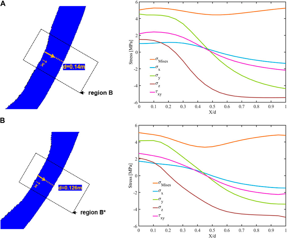
FIGURE 14. (A) The stress component distributions along the thinnest region (region B) of the RPV lower head for the SBO case at failure time t = 6.8 h. (B) The stress component distributions along the thinnest region (region B*) of the RPV lower head for the SBO + LOCA case at failure time t = 7.1 h.
To supplement the analysis of RPV structural response at the time of failure, Figures 15A, C show the deformation of the vessel lower head, reaching 8.4 cm in the SBO case and 9 cm in the SBO + LOCA case. Although the limit of deformation for the vessel lower head has not been explicitly defined here and elsewhere (as far as the authors know), the degree of deformation in these two accidents (i.e., 8.4 cm and 9 cm) is considered to pose a significant threat to the RPV structural integrity. For the same accident scenarios but with external cooling (Wang et al., 2021), it can be noted that these values are more than three times the values predicted at 12 h, which are 2.8 cm and 2.9 cm, respectively. The location of the large deformation (above 8 cm) for the SBO case is in the 24° to 42° section of the vessel (see Figure 15B), which is slightly outside and below the ablated region in the latitudinal direction. For the SBO + LOCA case (see Figure 15D) the section of the vessel with large displacement (35°–51° ) partly overlaps with the ablated region at angle 45°–51°. Hence, it can be inferred that the ablated region in the SBO + LOCA case is considered weaker than that in the SBO case given the macro-structural global deformation of the RPV.
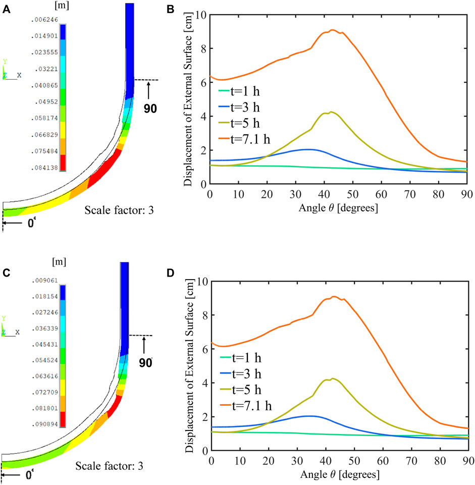
FIGURE 15. (A) Vector sum of displacement (scale factor = 3) at t = 6.8 h (failure time) for the SBO case. (B) Displacement of the external vessel surface at t = 1, 2, 3, and 6.8 h for the SBO case. (C) Vector sum of displacement (scale factor = 3) at t = 7.1 h (failure time) for the SBO + LOCA case. (D) Displacement of the external vessel surface at t = 1, 2, 3, and 7.1 h for the SBO + LOCA case.
Recall that in the structural analysis with ANSYS, the boundary conditions are transferred continuously from the output data in MELCOR by deactivating the failure modes. On the other hand, both SBO and SBO + LOCA accidents are simulated again in MELCOR with the failure modes, and the time and location of RPV failure can be extracted from the MELCOR output file. Table 5 compares the relevant information of RPV failure from MELCOR and ANSYS. In MELCOR, the vessel fails at t = 6.7 and 6.9 h, respectively, under these two accidents, resulting from the thru-wall yielding. This is the default failure criterion in MELCOR, indicating that the stress of the vessel wall exceeds the yield stress. Although MELCOR uses a different failure criterion, the failure time is close to the one obtained using ANSYS. Furthermore, the highly ablated regions, 60.93°–63.89° (segment 21) and 55.35°–57.88° (segment 19), are also identified as the failure location of the vessel wall, consistent with the results from ANSYS.
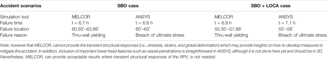
TABLE 5. Relevant information of RPV failure from MELCOR and ANSYS.
In this study, a framework involving the ANSYS and MELCOR platforms is established to study the behavior of a Nordic RPV lower head under SBO and SBO + LOCA. This one-way coupled method is particularly useful when the detailed investigation on the RPV behaviors is needed. Two failure criteria, the stress-based failure criterion and the strain-based failure criterion, have been used in assessing the mode and timing of RPV failure. In addition, a transient boundary condition (i.e., internal and external temperatures) is considered to simulate the dynamic process of vessel ablation. From the structural analysis, it is found that RPV failure initially occurs at 6.8 h in the SBO case and 7.1 h in the SBO + LOCA case, both attributed to a stress failure mechanism. Moreover, the axial normal stress
The framework and methodology presented here can be used in assessing structural integrity of the RPV in other types of nuclear reactor designs and provide the vessel failure analysis during a severe accident progression. It can also be used in analyzing the feasibility of different severe accident mitigation strategies with consideration of vessel thermo-mechanical behavior. In the future, the vessel penetrations (e.g., pump nozzles, Control Rod Guide Tubes, and Instrumentation Guide Tubes) on the RPV lower head will be considered to investigate other modes of vessel failure. This study provides a preliminary comparison of the RPV failure from ANSYS and MELCOR with their commonly used or default failure criteria; however, further investigation on RPV failure between these two codes is required with a unified failure criterion.
The raw data supporting the conclusion of this article will be made available by the authors, without undue reservation.
HW: writing—original draft preparation, methodology, and software. YC: MELCOR software and reviewing. WV: funding acquisition, supervision, writing, and reviewing.
This work is supported by the Swedish Radiation Safety Authority (SSM) Diarienr SSM2019-7689 and SSM2020-1192, the Swiss Federal Nuclear Safety Inspectorate (ENSI), and the Consortium of SSM and NPPs in Sweden (APRI). The authors are also grateful to the PhD scholarship awarded by the China Scholarship Council (CSC).
The authors declare that the research was conducted in the absence of any commercial or financial relationships that could be construed as a potential conflict of interest.
All claims expressed in this article are solely those of the authors and do not necessarily represent those of their affiliated organizations, or those of the publisher, the editors, and the reviewers. Any product that may be evaluated in this article, or claim that may be made by its manufacturer, is not guaranteed or endorsed by the publisher.
ADS, automatic depressurization system; BWR, boiling water reactor; FE, finite lement; NPP, nuclear power plant; NISO, nonlinear isotropic; RPV, reactor pressure vessel; SA, severe accident; SBO, station blackout; SBO + LOCA, station blackout with loss of coolant accident.
Amidu, M. A., Addad, Y., Lee, J. I., Kam, D. H., and Jeong, Y. H. (2021). Investigation of the Pressure Vessel Lower Head Potential Failure under IVR-ERVC Condition during a Severe Accident Scenario in APR1400 Reactors. Nucl. Eng. Des. 376, 111107. doi:10.1016/j.nucengdes.2021.111107
Amidu, M. A., Olatubosun, S. A., Ayodeji, A., and Addad, Y. (2021). Severe Accident in High-Power Light Water Reactors: Mitigating Strategies, Assessment Methods and Research Opportunities. Prog. Nucl. Energ., 104062.
Callister, W. D., and Rethwisch, D. G. (2011). Materials Science and Engineering, 5. NY: John Wiley & Sons.
Chen, Y., Zhang, H., Villanueva, W., Ma, W., and Bechta, S. (2019). A Sensitivity Study of MELCOR Nodalization for Simulation of In-Vessel Severe Accident Progression in a Boiling Water Reactor. Nucl. Eng. Des. 343, 22–37. doi:10.1016/j.nucengdes.2018.12.011
Devos, J., Sainte Catherine, C., Poette, C., and Burlet, H. (1999). CEA Programme to Model the Failure of the Lower Head in Severe Accidents. Nucl. Eng. Des. 191 (1), 3–15. doi:10.1016/s0029-5493(99)00049-7
Dietrich, P., Kretzschmar, F., Miassoedov, A., Class, A., Villanueva, W., and Bechta, S. (2015). Extension of the Nuclear Safety Code MELCOR. Pisa, Italy: Proc. 5th International Youth Conference on Energy IYCE.
Herranz, L. E., Fontanet, J., Fernández, E., and López, C. (2015). Influence of the Wet-Well Nodalization of a BWR3 Mark I on the Containment thermal-hydraulic Response during an SBO Accident. Nucl. Eng. Des. 295, 138–147. doi:10.1016/j.nucengdes.2015.09.031
Humphries, L., and Chu, T.-Y. (2002). OECD Lower Head Failure Project Final Report. Albuquerque, NM: Sandia National Laboratories, 87185–91139.
Humphries, L. L., Beeny, B. A., Gelbard, F., Louie, D. L., and Phillips, J. (2017). MELCOR Computer Code Manuals, Vol. 2. Albuquerque, NM: Reference Manual.
Kaneko, T., Tanaka, N., Yamaoka, T., Masaki, H., Masuda, Y., Iwanami, M., et al. (2015). Evaluation of Corrosion Behaviors for Reactor Pressure Vessels/primary Containment Vessels in Fukushima Daiichi Units 1-3 Nuclear Power Plant. J. Nucl. Sci. Techn. 52 (6), 773–783. doi:10.1080/00223131.2014.994048
Koundy, V., Durin, M., Nicolas, L., Combescure, A., et al. (2005). Simplified Modeling of a PWR Reactor Pressure Vessel Lower Head Failure in the Case of a Severe Accident. Nucl. Eng. Des. 235, 835–843. doi:10.1016/j.nucengdes.2004.11.012
Koundy, V., Fichot, F., Willschuetz, H.-G., Altstadt, E., Nicolas, L., Lamy, J.-S., et al. (2008). Progress on PWR Lower Head Failure Predictive Models. Nucl. Eng. Des. 238 (9), 2420–2429. doi:10.1016/j.nucengdes.2008.03.004
Li, L., Wang, M., Tian, W., Su, G., and Qiu, S. (2014). Severe Accident Analysis for a Typical PWR Using the MELCOR Code. Prog. Nucl. Energ. 71, 30–38. doi:10.1016/j.pnucene.2013.10.014
Mao, J. F., Zhu, J. W., Bao, S. Y., Luo, L. J., and Gao, Z. L. (2016). Investigation on Multilayer Failure Mechanism of RPV with a High Temperature Gradient from Core Meltdown Scenario. Nucl. Eng. Des. 310, 39–47. doi:10.1016/j.nucengdes.2016.10.005
Mao, J. F., Zhu, J. W., Bao, S. Y., Luo, L. J., and Gao, Z. L. (2016). Study on Structural Failure of RPV with Geometric Discontinuity under Severe Accident. Nucl. Eng. Des. 307, 354–363. doi:10.1016/j.nucengdes.2016.07.027
Mao, J., Hu, L., Bao, S., Luo, L., and Gao, Z. (2017). Investigation on the RPV Structural Behaviors Caused by Various Cooling Water Levels under Severe Accident. Eng. Fail. Anal. 79, 274–284. doi:10.1016/j.engfailanal.2017.04.029
Matejovic, P., Barnak, M., Bachraty, M., Vranka, L., and Berky, R. (2017). Adoption of In-Vessel Retention Concept for VVER-440/V213 Reactors in Central European Countries. Nucl. Eng. Des. 314, 93–109. doi:10.1016/j.nucengdes.2017.01.015
Naitoh, M., Pellegrini, M., Mizouchi, H., Suzuki, H., and Okada, H. (2013). Analysis of Accident Progression of Fukushima Daiichi NPPs with SAMPSON Code. in” International Conference on Nuclear Engineering. Chengdu, China: American Society of Mechanical Engineers (ASME). doi:10.1115/icone21-16805
Naitoh, M., Pellegrini, M., Mizouchi, H., Suzuki, H., and Okada, H. (2013). Analysis of Accident Progression of Fukushima Daiichi NPPs with SAMPSON codeInternational Conference on Nuclear Engineering. Chengdu, China: American Society of Mechanical Engineers (ASME), V006T015A023.
Pellegrini, M., Dolganov, K., Herranz, L. E., Bonneville, H., Luxat, D., Sonnenkalb, M., et al. (2016). Benchmark Study of the Accident at the Fukushima Daiichi NPS: Best-Estimate Case Comparison. Nucl. Techn. 196 (2), 198–210. doi:10.13182/nt16-63
Rempe, J.-L., Chavez, S.-A., and Thinnes, G. L. (1993). Light Water Reactor Lower Head Failure Analysis. Washington, DC (United States): Nuclear Regulatory CommissionDiv. of Systems Research.
Sehgal, B.-R., Theerthan, A., Giri, A., Karbojian, A., Willschütz, H. G., Kymäläinen, O., et al. (2003). Assessment of Reactor Vessel Integrity (ARVI). Nucl. Eng. Des. 221 (1-3), 23–53. doi:10.1016/s0029-5493(02)00343-6
Siegele, D., Hodulak, L., Varfolomeyev, I., and Nagel, G. (1999). Failure Assessment of RPV Nozzle under Loss of Coolant Accident. Nucl. Eng. Des. 193, 265–272. doi:10.1016/s0029-5493(99)00184-3
Villanueva, W., Filippov, A., Jules, S., Lim, K., Jobst, M., Bouydo, A., et al. (2020). Thermo-mechanical Modelling of Reactor Pressure Vessel during Core Melt In-Vessel Retention. in” Proc. of the International Seminar on In-vessel retention: outcomes of the IVMR project . France: Juan-les-Pins.
Villanueva, W., Tran, C.-T., and Kudinov, P. (2012). Coupled Thermo-Mechanical Creep Analysis for Boiling Water Reactor Pressure Vessel Lower Head. Nucl. Eng. Des. 249, 146–153. doi:10.1016/j.nucengdes.2011.07.048
Villanueva, W., Tran, C. T., and Kudinov, P. (2012). Analysis of Instrumentation Guide Tube Failure in a BWR Lower Head. Lausanne, Switzerland: NUTHOS-9.
Wang, H., Villanueva, W., Chen, Y., Kulachenko, A., and Bechta, S. (2021). Thermo-mechanical Behavior of an Ablated Reactor Pressure Vessel wall in a Nordic BWR under In-Vessel Core Melt Retention. Nucl. Eng. Des. 379, 111196. doi:10.1016/j.nucengdes.2021.111196
Willschütz, H. G., Altstadt, E., Sehgal, B., and Weiss, F. P. (2003). Simulation of Creep Tests with French or German RPV-Steel and Investigation of a RPV-Support against Failure. Ann. Nucl. Energ. 30, 1033–1063. doi:10.1016/S0306-4549(03)00036-7
Yue, Y., Villanueva, W., Wang, H., and Wang, D. (2020). Thermo-mechanical Analysis of Instrumentation Guide Tube Failure during a Severe Accident in a Nordic Boiling Water Reactor.in” Proc. Of the 28th International Conference on Nuclear Engineering (ICONE-28). Paper 16236, Virtual Conference. Online, USA.
Keywords: severe accident, reactor pressure vessel, structural integrity, finite element analysis, vessel failure criteria
Citation: Wang HD, Chen YL and Villanueva W (2022) Vessel Failure Analysis of a Boiling Water Reactor During a Severe Accident. Front. Energy Res. 10:839667. doi: 10.3389/fenrg.2022.839667
Received: 20 December 2021; Accepted: 12 January 2022;
Published: 14 February 2022.
Edited by:
Jun Wang, University of Wisconsin-Madison, United StatesReviewed by:
Muritala Amidu, Khalifa University, United Arab EmiratesCopyright © 2022 Wang, Chen and Villanueva. This is an open-access article distributed under the terms of the Creative Commons Attribution License (CC BY). The use, distribution or reproduction in other forums is permitted, provided the original author(s) and the copyright owner(s) are credited and that the original publication in this journal is cited, in accordance with accepted academic practice. No use, distribution or reproduction is permitted which does not comply with these terms.
*Correspondence: H. D. Wang, SG9uZ2RpQGt0aC5zZQ==
Disclaimer: All claims expressed in this article are solely those of the authors and do not necessarily represent those of their affiliated organizations, or those of the publisher, the editors and the reviewers. Any product that may be evaluated in this article or claim that may be made by its manufacturer is not guaranteed or endorsed by the publisher.
Research integrity at Frontiers
Learn more about the work of our research integrity team to safeguard the quality of each article we publish.