 Hui Cheng
 Songbai Cheng
 Jun Wang
- 1Sino-French Institute of Nuclear Engineering and Technology, Sun Yat-Sen University, Zhuhai, China
- 2College of Engineering, University of Wisconsin-Madison, Madison, WI, United States
In a core meltdown accident in light water reactors, molten corium may drop into the lower plenum of the pressure vessel and interact with water, which is called fuel–coolant interaction (FCI). The behavior of the corium jet breakup in water during FCIs is important for the in-vessel retention strategy and has been extensively studied. While in previous studies, the jet cross-section shapes are naturally assumed to be circular, which is actually not always the case, in this study, the breakup processes of the corium jets with four different elliptical cross-section shapes and three different penetration velocities are simulated with color-gradient lattice Boltzmann method. The effect of the cross-section shape on the hydrodynamic breakup behavior of the corium jet is analyzed in detail. It is found that the effect of the cross-section shape on the jet penetration depth is very limited. With the increase in the aspect ratio under the same penetration velocity, the jet breakup length decreases gradually. In general, the dimensionless corium surface area increases with the increase in the aspect ratio for the jets under the same penetration velocity.
1 Introduction
During a core meltdown accident in light water reactors (LWRs), molten corium may drop into the lower plenum of the reactor vessel and interact with water, which is called fuel–coolant interaction (FCI). The design of the in-vessel retention (IVR) strategy requires the full understanding of the physical phenomena related to FCIs, especially the corium jet breakup process which will significantly affect the formation of the debris bed and the subsequent in-vessel cooling. The corium jet breakup behavior in water has been extensively studied with real core material experiments, simulant material experiments, and various simulations (Spencer et al., 1994;Burger et al., 1995;Dinh et al., 1999;Huhtiniemi et al., 1999;Abe et al., 2006;Thakre et al., 2015;Zhou et al., 2017;Iwasawa and Abe 2018;Saito et al., 2018;Shen et al., 2018;Cheng et al., 2019;Cheng et al., 2020;Cheng et al., 2021a;Cheng et al., 2021b). To the best of authors’ knowledge, in almost all of the previous studies, the jet cross-section shapes are naturally assumed to be circular, which is actually not always the case. In fact, when the molten corium drops from the edge of the core, through the structures or the cracks of the corium crust, the corium jets are very likely to have different cross-section shapes depending on the specific situations (Corradini et al., 1988). This leads to the investigation of the effect of jet cross-section shape on the corium jet breakup behavior, which was generally ignored in previous studies.
Since the interaction between the molten corium jet and water involves very complex thermal hydraulics phenomena such as boiling heat transfer, corium jet breakup, and corium solidification, it is not easy to get the effect of jet cross-section shape directly from the experimental results with such complex phenomena. On the other hand, more quantitative results can be directly extracted from the numerical results, among which the lattice Boltzmann method (LBM) has become a powerful tool in analyzing the complex multiphase flow in recent years (Saito et al., 2017). LBM is the so-called mesoscopic simulation method between the microscopic particle-based (molecular dynamics) and macroscopic Navier–Stokes–based methods. Compared with conventional CFD methods, it has the following advantages: 1) based on the molecular kinetic theory; 2) easy to program and parallelize; 3) interface tracking is not needed; and 4) applicable to complex geometries (Huang et al., 2015;Krüger et al., 2016). As one of the two-phase LBM methods, the color-gradient LBM employs two components to represent two immiscible fluids; one component is the red-colored fluid and the other is the blue-colored fluid. Its main advantages lie in strict mass conservation for each fluid and flexibility in adjusting the interfacial tension (Ba et al., 2016). To simplify the complex situation involved, in the current study, the hydrodynamic phenomena are decoupled from the thermal phenomena and studied separately for the corium jet breakup process with the state-of-the-art GPU-accelerated color-gradient LBM.
In this study, the breakup process of the corium jets with four different elliptical cross-section shapes and three different penetration velocities are simulated with color-gradient LBM. The effect of the cross-section shape on the hydrodynamic breakup behavior of the corium jet is analyzed in detail.
2 Color-Gradient Lattice Boltzmann Method
In our previous studies, the improved color-gradient LBM with non-orthogonal central-moment MRT has been successfully developed and used to study the hydrodynamic breakup process of melt jets with circular cross-section in both sodium-cooled fast reactors (SFRs) (Cheng et al., 2020) and LWRs (Cheng et al., 2021b), thanks to its advantages in multiphase flow modeling and the enhanced numerical stability for flows with high Reynolds numbers. Here, this model is adopted in the current work to explore the effect of jet cross-section shape on the corium jet hydrodynamic breakup behavior. The details of the improved color-gradient LBM are introduced as follows.The D3Q27 lattice is adopted; the discrete lattice velocity
where index
Two immiscible fluids are represented by pseudo red fluid and blue fluid, respectively. The distribution function,
where
where
2.1 Single-Phase Collision Operator
The single-phase collision operator with non-orthogonal central moment MRT is defined as
where transformation matrix
where
where
In the single-phase collision operator, the enhanced equilibrium distribution function (Leclaire et al., 2017) is used
The weights,
Meanwhile, we have
where
where
where
To ensure stable interface,
where the superscript “0” over
In this study, we chose
2.2 Perturbation Operator
The interfacial tension in the color-gradient LBM is modeled with the perturbation operator given by
where
The interfacial tension
where
2.3 Recoloring Operator
This operator is employed to maximize the amount of fluid
where
2.4 Streaming Operator
where
2.5 Macro Properties and Gradient Operator
The density of each fluid and the total fluid are defined as
The total momentum is defined as
The second-order isotropic central scheme is adopted to define the gradient operator for any function
3 Computational Domain and Parameters
The computational domain for the corium jet breakup process is presented in Figure 1, which includes a water pool and an inlet at the top surface where the corium jet is penetrated. The other surfaces are set as convective boundary conditions so that the dispersion of the corium will not be limited by the boundary of the computational domain. As an example, the convective boundary condition at the bottom surface is given by
where
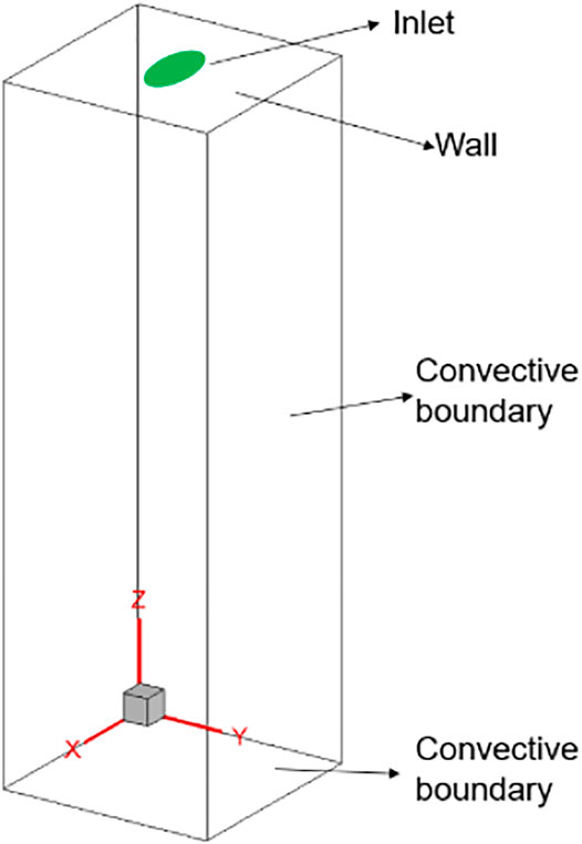
FIGURE 1. Computational domain for the corium jet breakup process.
The body force is given by
where
To study the effect of the jet cross-section shape on the corium jet hydrodynamic breakup behavior, the penetration processes of the corium jets with four different elliptical cross-section shapes and three different penetration velocities are simulated. The parameters for all 12 cases are presented in Table 1, where “a” is the semi-major axis of the ellipse, “b” is the semi-minor axis of the ellipse, and “E = a/b” is the aspect ratio. All these elliptical cross-sections have the same area which is equal to a circular area with 10 mm diameter, so that the penetration flow rates remain the same for the corium jets with the same penetration velocity. The three penetration velocities
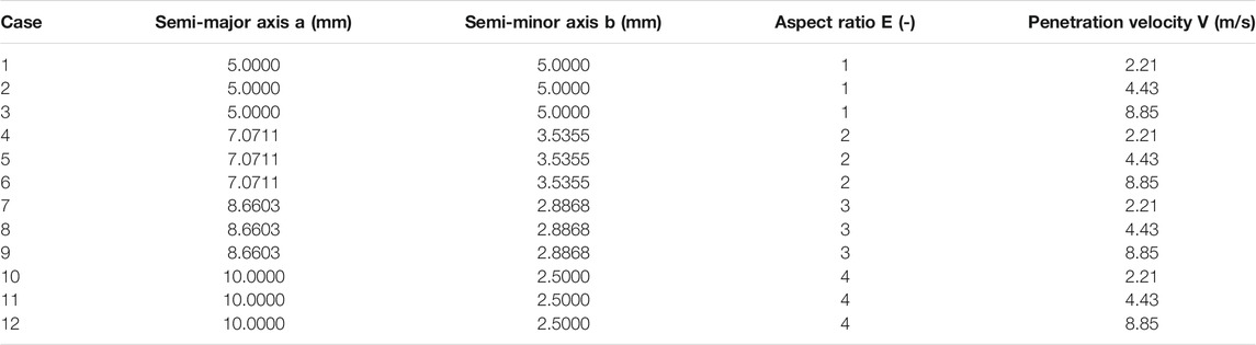
TABLE 1. Parameters of the corium jets with four elliptical cross-sections and three velocities.
In the current simulations, the corium is set to a mixture of 80% UO2 and 20% ZrO2 (mol%) with a melting point of 2,600°C. It is assumed that corium jet at 3,000°C is penetrated into water at 70°C. The thermophysical properties of the corium at 3,000°C and water at 70°C are presented in Table 2 (Schins1978; Kirillov2006; Kolev 2015; Kim et al., 2017).
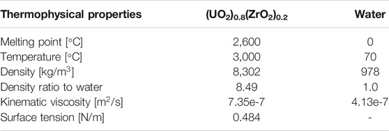
TABLE 2. Thermophysical properties of the corium.
To conduct the simulations with LBM, all parameters are converted from physical units to lattice units based on Eqs 31–34, where
In our previous studies (Cheng et al., 2020; Cheng et al., 2021b), lattice number independent tests have been conducted by dividing the computational domain into 78*78*250,104*104*330, 130*130*410, and160*160*500 lattices, and it is found that the difference of the simulation results can be ignored for the last two; hence, 160*160*500 lattices with
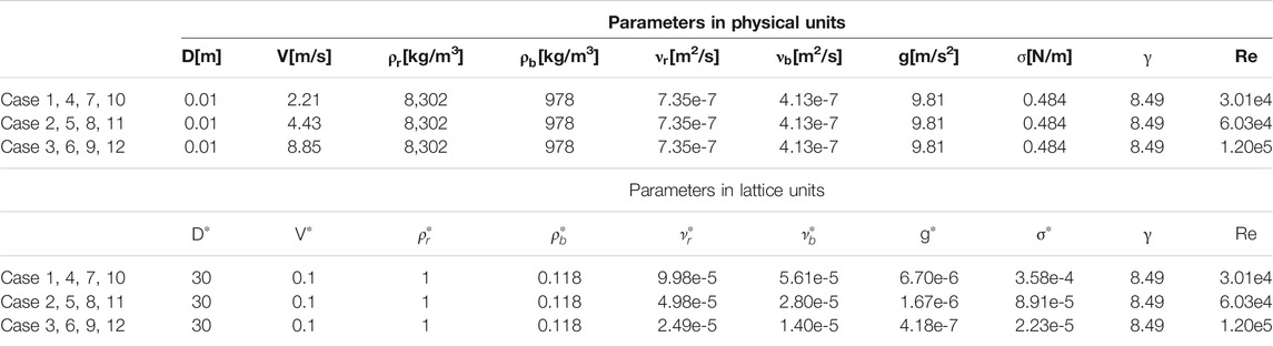
TABLE 3. Parameters in physical units and lattice units.
4 Results and Discussion
4.1 Morphology of Corium Jet Breakup
The snap shots of corium jet breakup processes along both minor axis direction and major axis direction of the elliptical cross-section in the 12 cases are presented in Figure 2, where the interface between the corium and the water is extracted from the simulation results. It can be seen that for all 12 cases under different conditions, a mushroom-shaped leading edge can be observed immediately after the penetration due to the drag force, and then both the jet leading edge and jet column start to break up under the effect of Rayleigh–Taylor instability and Kelvin–Helmholtz instability, respectively; lots of small fragments are generated along with the penetration process.
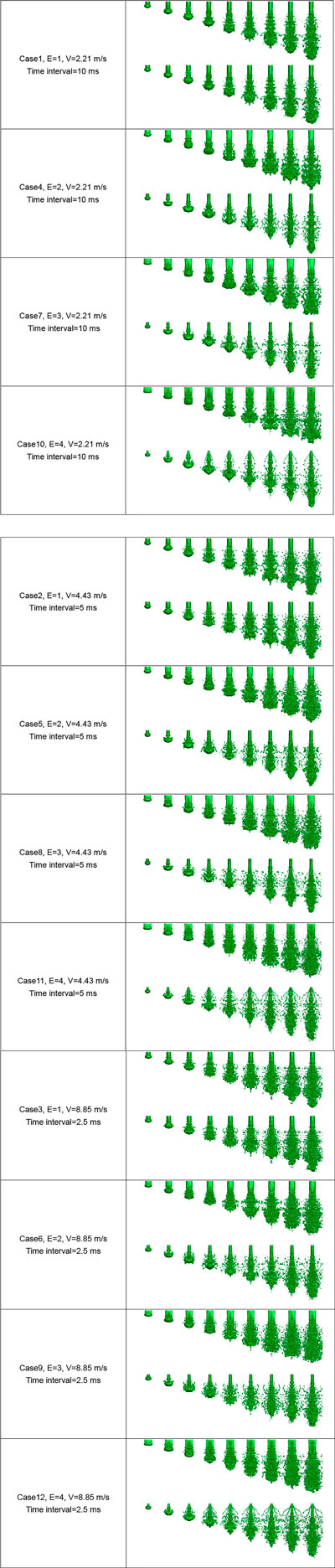
FIGURE 2. Snap shots of corium jet breakup processes in the 12 cases.
Qualitatively, it is easy to find that more fragments are generated with the increase in the penetration velocity for the corium jets with the same aspect ratio (e.g., comparing Case 1, Case 2, and Case 3). The effect of the aspect ratio on the generated fragments for the corium jets with the same penetration velocity is not directly based on these figures, which is further analyzed quantitatively in Section 4.4 Nevertheless, it can be noticed that with the increase in the aspect ratio, the jet becomes more flat and more fragments are distributed along the major axis direction than along the minor axis direction.
4.2 Jet Penetration Depth
The penetration depth versus time of the corium jet under three different penetration velocities is presented in Figure 3. From these figures, it can be seen that the effect of the cross-section shape on the jet penetration depth is very limited. The penetration depth changes little even when the aspect ratio changes from 1 to 4. This is because the penetration depth is mainly affected by the drag force; though the aspect ratio changes a lot, the drag force still changes very little for jets with the same penetration velocity and cross-section area.
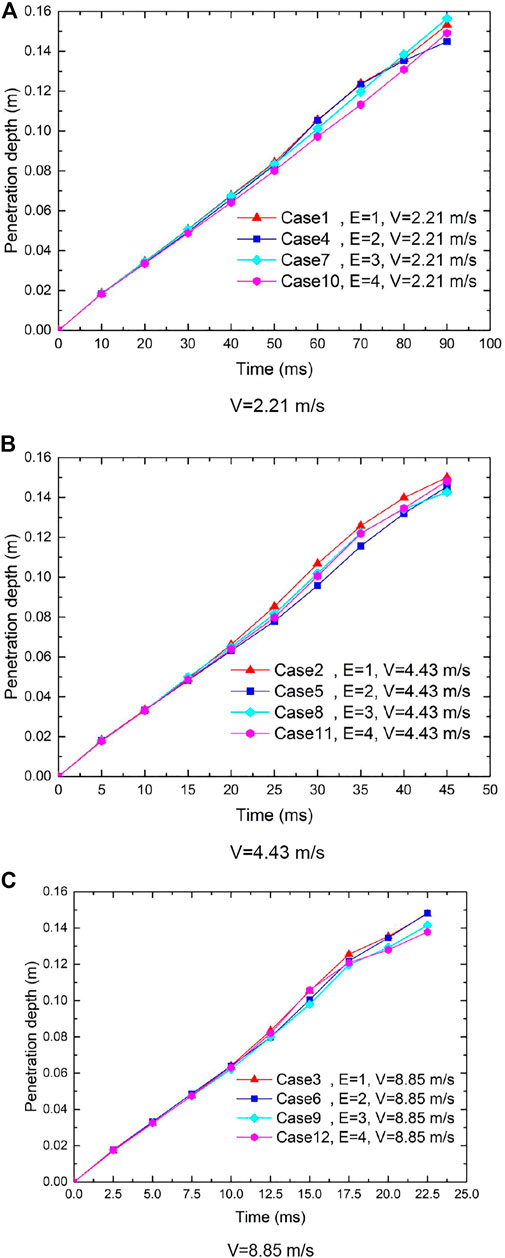
FIGURE 3. Jet penetration depth vs. time.
4.3 Jet Breakup Length
The jet breakup length, the distance from free surface to the breakup point, is an important parameter to evaluate whether molten corium will directly come in contact with the lower plenum of the pressure vessel before it sufficiently breaks up. Once the length is longer than the water depth, the pressure vessel is likely to be melted through by the molten corium, which might cause the radioactive material leakage (Iwasawa and Abe 2018). In the melt jet breakup experiments, the jet breakup length usually can hardly be measured directly from the observation because the jet column is covered by lots of fragments similar to those in Figure 2, while with the simulations in the current study, the jet breakup length can be easily extracted from the middle cross-sectional density contours as shown in Figure 4, where Case 4 and Case 10 are presented. The breakup position can be easily observed from these figures. It should be noted that the jet column may break up in one middle cross-section view (e.g., major axis direction) but actually still connect in another middle cross-section view (e.g., minor axis direction) since the jet morphology is not axially symmetric. Hence, the jet column should be disconnected in both views when checking the breakup point. Furthermore, the breakup point usually fluctuates during the penetration process; here, the maximum jet breakup length is used as the jet breakup length in this study.
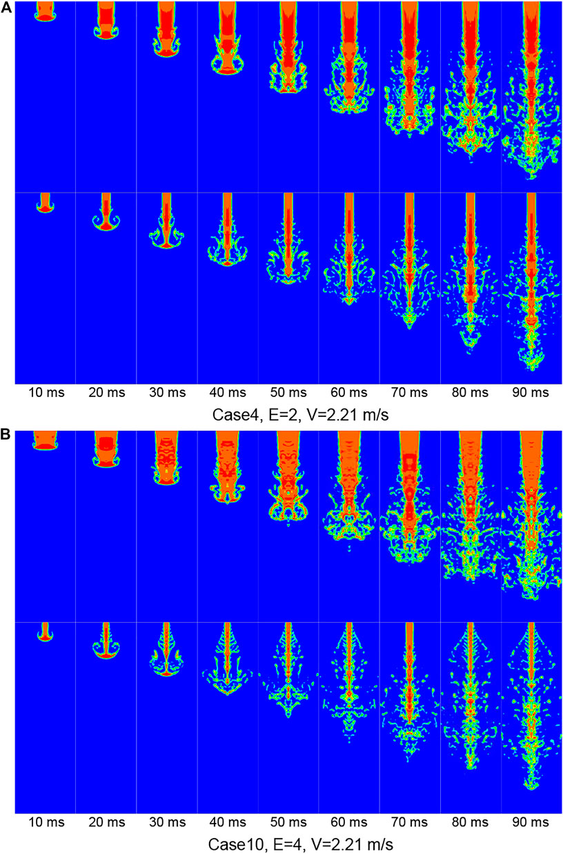
FIGURE 4. Middle cross-sectional density contours along both major axis direction and minor axis direction.
The dimensionless jet breakup length is defined as
where
The dimensionless jet breakup length versus aspect ratio in the 12 cases is shown in Figure 5. First, it is clear that with the increase in the penetration velocity under the same aspect ratio, the breakup length decreases gradually. This is because higher penetration velocity will enhance the stripping from the jet column due to the Kelvin–Helmholtz instability, and the material is removed from the jet column faster, which leads to the faster disconnection of the jet column and the shorter breakup length.
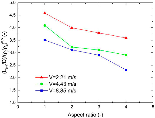
FIGURE 5. Dimensionless jet breakup length vs. aspect ratio in the 12 cases.
It can also be found that with the increase in the aspect ratio under the same penetration velocity, the jet breakup length decreases gradually. This can be explained as follows: The intensity of the stripping is determined not only by the penetration velocity but also by the contact area between the jet and water, since the contact area increases with the increase in the aspect ratio under the same cross-section area, namely, the jet becomes flat, and the stripping is enhanced. On the other hand, the thickness of the jet along the minor axis direction becomes smaller with the increase in the aspect ratio. Hence, the jet column is easier to break up due to stripping at a higher aspect ratio. This phenomenon can be clearly observed in Figure 4 by comparing Case 4 and Case 10 with an aspect ratio of 2 and 4, respectively.
4.4 Degree of the Fragmentation
Since the fragments generated during the jet penetration process are mostly irregular as shown in Figure 2, direct measurement of the fragment size will introduce large errors. In this work, the dimensionless corium surface area is used to evaluate the degree of the jet fragmentation. First, the interface between the corium and water is extracted from the simulation results as shown in Figure 2; then, the interface area
The dimensionless corium surface area versus aspect ratio at approximately the same penetration depth (V*t) in the 12 cases is presented in Figure 6. It can be seen that the dimensionless corium surface area increases with the increase in the penetration velocity for the jets with the same aspect ratio, that is, smaller fragments are generated with the increase in the penetration velocity. This is because higher penetration velocity means stronger momentum exchange and stripping, leading to more fragments.
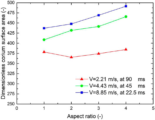
FIGURE 6. Dimensionless corium surface area vs. aspect ratio at approximately the same penetration depth in the 12 cases.
Another observation is that, in general, the dimensionless corium surface area increases with the increase in the aspect ratio for the jets under the same penetration velocity. This trend is not obvious at low penetration velocity (e.g., V = 2.21 m/s), but remarkable at high penetration velocities. The reason has been explained in Section 4.3, namely, with the increase in the aspect ratio under the same cross-section area, the contact area between the jet and water is increased, which enhances the stripping and facilitates the jet fragmentation.
5 Conclusion
In order to investigate the effect of jet cross-section shape on the corium jet breakup behavior, which is generally ignored in previous studies, in this study, the breakup processes of the corium jets with four different elliptical cross-section shapes and three different penetration velocities are simulated with the state-of-the-art GPU-accelerated color-gradient lattice Boltzmann method. The effect of the cross-section shape on the hydrodynamic breakup behavior of the corium jet is analyzed in detail. Three main conclusions drawn from the simulation results are as follows:
(1)The effect of the cross-section shape on the jet penetration depth is very limited because the change of the drag force is very small for jets with the same penetration velocity and cross-section area.
(2)With the increase in the aspect ratio under the same penetration velocity, the jet breakup length decreases gradually mainly due to the decrease in the thickness of the jet along the minor axis direction.
(3)In general, the dimensionless corium surface area increases with the increase in the aspect ratio for the jets under the same penetration velocity since the contact area increases with the increase in the aspect ratio under the same cross-section area.
Data Availability Statement
The raw data supporting the conclusions of this article will be made available by the authors, without undue reservation.
Author Contributions
HC contributed to the conception and simulations of this study and writing the manuscript; SC and JW contributed to manuscript revision and read and approved the submitted version.
Funding
This work was supported by the Fundamental Research Funds for the Central Universities of Sun Yat-sen University (No. 2021qntd12), the basic and applied basic research foundation of Guangdong province (No. 2021A1515010343), and the Science and Technology Program of Guangdong Province (No. 2021A0505030026).
Conflict of Interest
The authors declare that the research was conducted in the absence of any commercial or financial relationships that could be construed as a potential conflict of interest.
Publisher’s Note
All claims expressed in this article are solely those of the authors and do not necessarily represent those of their affiliated organizations, or those of the publisher, the editors, and the reviewers. Any product that may be evaluated in this article, or claim that may be made by its manufacturer, is not guaranteed or endorsed by the publisher.
References
Abe, Y., Matsuo, E., Arai, T., Nariai, H., Chitose, K., Koyama, K., et al. (2006). Fragmentation Behavior during Molten Material and Coolant Interactions. Nucl. Eng. Des.236, 1668–1681. doi:10.1016/j.nucengdes.2006.04.008
Ba, Y., Liu, H., Li, Q., Kang, Q., and Sun, J. (2016). Multiple-relaxation-time Color-Gradient Lattice Boltzmann Model for Simulating Two-phase Flows with High Density Ratio. Phys. Rev. E94, 023310. doi:10.1103/PhysRevE.94.023310
Bürger, M., Cho, S. H., Berg, E. v., and Schatz, A. (1995). Breakup of Melt Jets as Pre-condition for Premixing: Modeling and Experimental Verification. Nucl. Eng. Des.155, 215–251. doi:10.1016/0029-5493(94)00875-y
Cheng, H., Chen, X., Ye, Y., and Cheng, S. (2021a). Systematic Experimental Investigation on the Characteristics of Molten lead-bismuth Eutectic Fragmentation in Water. Nucl. Eng. Des.371, 110943. doi:10.1016/j.nucengdes.2020.110943
Cheng, H., Cheng, S., and Zhao, J. (2020). Study on Corium Jet Breakup and Fragmentation in Sodium with a GPU-Accelerated Color-Gradient Lattice Boltzmann Solver. Int. J. Multiphase Flow126, 103264. doi:10.1016/j.ijmultiphaseflow.2020.103264
Cheng, H., Zhao, J., Saito, S., and Cheng, S. (2021b). Study on Melt Jet Breakup Behavior with Nonorthogonal central-moment MRTColor-Gradient Lattice Boltzmann Method. Prog. Nucl. Energ.136, 103725. doi:10.1016/j.pnucene.2021.103725
Cheng, H., Zhao, J., and Wang, J. (2019). Experimental Investigation on the Characteristics of Melt Jet Breakup in Water: The Importance of Surface Tension and Rayleigh-Plateau Instability. Int. J. Heat Mass Transfer132, 388–393. doi:10.1016/j.ijheatmasstransfer.2018.12.026
Corradini, M. L., Kim, B. J., and Oh, M. D. (1988). Vapor Explosions in Light Water Reactors: A Review of Theory and Modeling. Prog. Nucl. Energ.22, 1–117. doi:10.1016/0149-1970(88)90004-2
Dinh, T. N., Bui, V. A., Nourgaliev, R. R., Green, J. A., and Sehgal, B. R. (1999). Experimental and Analytical Studies of Melt Jet-Coolant Interactions: a Synthesis. Nucl. Eng. Des.189, 299–327. doi:10.1016/s0029-5493(98)00275-1
Huang, H., Sukop, M., and Lu, X. (2015). Multiphase Lattice Boltzmann Methods: Theory and Application.
Huhtiniemi, I., Magallon, D., and Hohmann, H. (1999). Results of Recent KROTOSFCI Tests: Alumina versus Corium Melts. Nucl. Eng. Des.189, 379–389. doi:10.1016/s0029-5493(98)00269-6
Iwasawa, Y., and Abe, Y. (2018). Melt Jet-Breakup and Fragmentation Phenomena in Nuclear Reactors: A Review of Experimental Works and Solidification Effects. Prog. Nucl. Energ.108, 188–203. doi:10.1016/j.pnucene.2018.05.009
Kim, W. K., Shim, J. H., and Kaviany, M. (2017). Thermophysical Properties of Liquid UO2, ZrO2 and Corium by Molecular Dynamics and Predictive Models. J. Nucl. Mater.491, 126–137. doi:10.1016/j.jnucmat.2017.04.030
Kirillov, P. (2006). Thermo Physical Properties of Materials for Nuclear Engineering. Obninsk: Institute for heat and mass transfer in nuclear power plants.
Krüger, T., Kusumaatmaja, H., Kuzmin, A., Shardt, O., Silva, G., and Viggen, E. M. (2016). The Lattice Boltzmann Method - Principles and Practice.
Leclaire, S., Parmigiani, A., Malaspinas, O., Chopard, B., and Latt, J. (2017). Generalized Three-Dimensional Lattice Boltzmann Color-Gradient Method for Immiscible Two-phase Pore-Scale Imbibition and Drainage in Porous media. Phys. Rev. E95, 033306. doi:10.1103/PhysRevE.95.033306
Saito, S., Abe, Y., and Koyama, K. (2017). Lattice Boltzmann Modeling and Simulation of Liquid Jet Breakup. Phys. Rev. E96, 013317f. doi:10.1103/PhysRevE.96.013317
Saito, S., De Rosis, A., Festuccia, A., Kaneko, A., Abe, Y., and Koyama, K. (2018). Color-gradient Lattice Boltzmann Model with Nonorthogonal central Moments: Hydrodynamic Melt-Jet Breakup Simulations. Phys. Rev. E98, 013305. doi:10.1103/PhysRevE.98.013305
Schins, H. (1978). On the Surface Tension of Liquid UO2. J. Nucl. Mater.78, 215–216. doi:10.1016/0022-3115(78)90521-4
Shen, P., Zhou, W., Cassiaut-Louis, N., Journeau, C., Piluso, P., and Liao, Y. (2018). Corium Behavior and Steam Explosion Risks: A Review of Experiments. Ann. Nucl. Energ.121, 162–176. doi:10.1016/j.anucene.2018.07.029
Spencer, B., Wang, K., Blomquist, C., Mcumber, L., and Schneider, J. (1994). Fragmentation and Quench Behavior of Corium Melt Streams in Water". Nuclear Regulatory Commission. Washington, DCIL (United States)): United States. Div. of Systems Research; Argonne National Lab..
Thakre, S., Manickam, L., and Ma, W. (2015). A Numerical Simulation of Jet Breakup in Melt Coolant Interactions. Ann. Nucl. Energ.80, 467–475. doi:10.1016/j.anucene.2015.02.038
Keywords: fuel–coolant interaction (FCI), corium jet breakup, effect of jet cross-section shape, lattice Boltzmann method, jet breakup length
Citation: Cheng H, Cheng S and Wang J (2022) Numerical Study on the Effect of Jet Cross Section Shape on the Corium Jet Breakup Behavior With Lattice Boltzmann Method. Front. Energy Res. 10:834237. doi: 10.3389/fenrg.2022.834237
Received: 13 December 2021; Accepted: 12 January 2022;
Published: 10 February 2022.
Edited by:
Yixiang Liao, Helmholtz Association of German Research Centres (HZ), GermanyReviewed by:
Luteng Zhang, Chongqing University, ChinaRong Liu, South China University of Technology, China
Copyright © 2022 Cheng, Cheng and Wang. This is an open-access article distributed under the terms of the Creative Commons Attribution License (CC BY). The use, distribution or reproduction in other forums is permitted, provided the original author(s) and the copyright owner(s) are credited and that the original publication in this journal is cited, in accordance with accepted academic practice. No use, distribution or reproduction is permitted which does not comply with these terms.
*Correspondence:Songbai Cheng, Y2hlbmdzYjNAbWFpbC5zeXN1LmVkdS5jbg==; Jun Wang, andhbmc1NjRAd2lzYy5lZHU=