 Han Deng 1
 Jingyang Fang 2*
- 1Interdisciplinary Graduate Programme, Nanyang Technological University, Singapore, Singapore
- 2School of Control Science and Engineering, Shandong University, Jinan, China
The ever-increasing integration of power converter-coupled renewable energy sources reduces carbon footprints yet weakens power system inertia due to the retirement of synchronous generators. Inertia shortage makes modern power systems sensitive to frequency variations, thereby leading to undesirable load shedding, cascading failures, or even large-scale blackouts. To address the inertia concern, distributed virtual inertia from grid-tied power converters is emerging as an attractive solution. On top of that, there are upcoming standards of grid-tied power converters, such as PV inverters, that require grid formulation. As such, this paper proposes flexible distributed virtual inertia delivered by grid-forming converters without additional energy storage units. It is revealed that virtual inertia control may possibly cause stability problems. Through the derived state-space model and sensitivity analysis, the mechanism of instability is disclosed. Although droop control may stabilize converters, it inevitably necessitates extra energy storage, and is hence not cost-effective. Instead, a lead compensator, together with its design procedure, is proposed. Finally, simulation and experimental results validate the correctness and effectiveness of the proposed model and compensator. Moreover, the results demonstrate that the proposed grid-forming converters allow significant improvements in inertia and frequency regulation.
1 Introduction
In bulky power systems, the per unit kinetic energy stored in the rotors of synchronous generators (SGs), defined as inertia, automatically mitigates frequency deviations and stabilizes the mains frequency (Fang et al., 2018b). To reduce carbon footprints, distributed generators (DGs) fed by renewable energy sources (RESs), such as solar and wind, are gradually replacing SGs in modern power systems (REN21 2020). However, DGs are normally coupled to grids through power electronic converters, which mainly track maximum power points without contributing any inertia (Blaabjerg et al., 2004, Blaabjerg et al., 2006). Therefore, inertia continues to reduce with the growing penetration of DGs, thus threatening the frequency regulation of modern grids. Specifically, inertia shortage causes excessive rate of change of frequency (RoCoF) and large frequency swings under contingencies (e.g., load and SG tripping events), resulting in cascading failures and/or even large scale blackouts (Kundur 1994). Consequently, it is essential to increase inertia and improve frequency regulation. Among inertia enhancement schemes, inertia delivery through grid-connected converters (GCCs), with or without additional energy storage, is preferable than redundant SGs or synchronous condensers in terms of cost (Fang et al., 2018b).
According to (Rocabert et al., 2012), GCCs can broadly be categorized into grid-feeding (GFDCs) and grid-forming converters (GFMCs), which are equivalent to controllable current and voltage sources, respectively. Most commercial GCCs work as GFDCs due to their tight current control and technology maturity (Piya et al., 2018; Zhang et al., 2021). However, GFDCs fail to form voltage and frequency under islanded conditions. They must follow the point of common coupling (PCC) voltages and track their phase angles, e.g., through phase-locked loops (PLLs). In addition, GFDCs are prone to instability in weak grids (Ashabani and Mohamed 2014). In contrast, GFMCs regulate ac voltages and their frequency either directly or according to their power references. As such, GFMCs allow standalone operation and seamless transitions between isolated and grid-connected modes. After a successful grid connection, PLLs are no longer necessary in GFMCs (Qing-Chang et al., 2014). Due to the above-mentioned advantages, GFMCs enjoy growing popularity for grid support (Khajehoddin et al., 2019; Quan et al., 2020).
During the past decade, many control strategies were proposed to deliver inertia through GFMCs (Lasseter et al., 2020). For example, a well-known concept, known as virtual synchronous machines (VSMs) (Wu et al., 2016), virtual synchronous generators (VSGs) (Zhong and Weiss 2011; Qing-Chang et al., 2014) and static synchronous generators (SSGs) (Xiong et al., 2016) intends to integrate the voltage and frequency dynamics of SGs into GFMCs. In particular, the swing equation, which models the mechanical behaviors of SGs, enables VSMs to deliver virtual inertia (Kundur 1994). Alternatively, droop control, when combined with low-pass filters, is claimed to be equivalent to the swing equation (D’Arco and Suul 2014), thereby allowing VSMs to contribute virtual inertia. As for power-synchronization control (Zhang et al., 2010; Zhang et al., 2011), GCCs emulate the synchronization mechanism of VSMs. However, power-synchronization control involves only droop control without inertia emulation, hence it cannot handle excessive RoCoF events. As a nonlinear time-domain controller, the virtual oscillator control emulates the dynamics of limit-cycle oscillators (Johnson et al., 2016). Despite showing promise in terms of large-signal stability, virtual oscillators suffer from complex mathematical foundations and ideal assumptions (Awal et al., 2020). Apart from the controller design, the small-signal stability and transient stability of VSMs have also been discussed in literature (Xiong et al., 2016; Xiong et al., 2020; Yuan et al., 2021).
VSMs incorporating the swing equation mimic both inertia and droop (or damping) of SGs. Frequency droop control changes the active power reference of VSMs as per grid frequency deviations. In this way, droop control can damp low-frequency oscillations (Wu et al., 2016). A generalized droop control for VSM with good dynamic performance under both grid-connected and standalone mode is proposed in (Meng et al., 2019). However, the price paid for droop is a continuous power injection under contingencies, as long as frequency deviations exist. This implies that VSMs must employ energy storage units (such as batteries and flywheels) to achieve the swing equation (Fang et al., 2018c), thus leading to the extra cost of energy storage and system complexity. In addition, although large droop coefficients translate into better stability, they may overload or even trip VSMs under large frequency drifts (Xin et al., 2016). In other words, droop coefficients are limited by the capacity of VSMs.
Alternatively, it is preferable to use existing GCCs without additional energy storage for only inertia emulation. For GFDCs, inertia emulation is simply achieved by proportionally changing their dc capacitor voltages in response to the mains frequency (Fang et al., 2018a; Fang et al., 2018b; Fang et al., 2018d). This method benefits from no or minor hardware changes, simplicity, and flexibility. However, when transplanted to GFMCs, it is found that inertia emulation brings instability (Hirase et al., 2016; Han et al., 2019). We will analyze the mechanism of instability in this article.
To get rid of the instability related to inertia delivery, (Ebrahimi et al., 2019) modify the frequency droop, which links the difference between the inverter frequency and the grid frequency instead of the nominal frequency to improve stability. As the grid and GFMC share the same frequency in steady state, the GFMC can be stabilized without any additional steady-state power output. However, PLLs should always operate. The power system stabilizer relates the frequency deviation with the voltage amplitude to stabilize SGs (Chen et al., 2017; Ebrahimi et al., 2019). However, the active power and reactive power are mainly associated with the frequency and voltage amplitude, respectively. Therefore, power system stabilizers are not directly applicable to GFMCs with distributed inertia. (Dong and Chen 2017; Dong and Chen 2018). proposed damping correction loop to damp the oscillation caused by the virtual inertia, while derivative term of frequency is introduced, which will cause instability problems. (Liu et al., 2016). uses a lead-lag compensator to emulate stable inertia, while sudden frequency change will be introduced by load disturbances, which will be harmful to frequency-sensitive loads. Consequently, a research gap on the stabilization of GFMCs delivering inertia without extra energy storage remains.
This paper proposes a lead compensator for stability improvement. With the proposed compensator, GFMCs can provide flexible and distributed inertia even without additional energy storage. A detailed state-space model of GFMCs is derived. Based on the derived model, we conduct the stability analysis of GFMCs with different controllers. The rest of this paper is organized as follows: Section 3 derives a detailed state-space small-signal model of GFMCs. Section 4 performs stability analysis based on the derived model. Section 5 proposes a lead compensator for flexible inertia emulation. Section 6 verifies the derived model and the proposed control strategies by simulations and experiments. Finally, Section 7 summarizes the paper.
2 Small-Signal Modeling of Grid-Forming Converters
This section introduces the system configuration and derives the detailed small-signal model. The small-signal model is fractionated into several parts, which are introduced separately. Finally, the individual parts constitute an overall model.
2.1 System Configuration
Figure 1 shows the system configuration, where the grid-forming converter is connected to the grid through an LCL filter, which consists of Lgi, Cgf, and Lgg. The power grid is modeled as a serial connection of grid inductors Ls and voltage sources vsabc. The basic control objectives of a grid-forming converter are to regulate the active power P and reactive power Q injected to the power grid through the active power controller (APC) and the reactive power controller (RPC), respectively. pg_c and qg_c represents the measured active and reactive power, and pg_ref and qg_ref are the references for pg_c and qg_c, respectively. The APC regulates the phase angle reference ωot of the capacitor voltages vgfabc, and the RPC tunes the voltage amplitude reference vgfd_ref. As shown in Figure 1, the cascaded voltage controller Gv(s) and current controller Gc(s) are implemented in the synchronous dq-frame to control the capacitor voltages vgfabc and the converter-side currents igiabc, respectively. The subscripts d and q represent the signals in the d and q axes, respectively. vgiabc denote the inverter voltages, and iggabc represent the currents flowing from the converter to the grid.
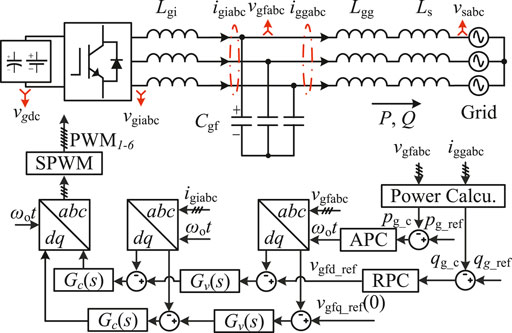
FIGURE 1. System configuration of grid-forming converters.
The overall system comprises the system plant, the voltage and current controllers, the power controllers, and the sampling and update parts, which will separately be introduced in the following subsections.
2.2 Modeling of the System Plant
Figure 2A models the system plant in the synchronous dq frame, where vsq = 0, ω1 denotes the fundamental angular frequency, Δ represents the small-signal perturbation, and the subscript ref stands for the reference value. Correspondingly, the small-signal state-space model of the system plant is
where
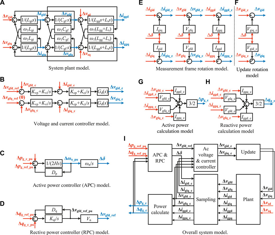
FIGURE 2. Small-signal model of grid-forming converters.
The expressions of Aplant and Bplant can be seen from Supplementary Appendix SA1
2.3 Modeling of Voltage and Current Controllers
Figure 2B depicts the voltage and current controllers in the synchronous dq frame, where vgfq_ref = 0. The subscript c refers to signals in the control frame. Proportional integral (PI) controllers serve as the voltage and current controllers, where Kvp and Kvi as well as Kcp and Kci represent the proportional and integral gains of the voltage controllers as well as the current controllers, respectively.
Gd(s) denotes the delay introduced by computation and pulse width modulation (PWM). In this article, the sampling frequency fs and switching frequency fsw are designed to be identical, i.e. fs = fsw = 1/Ts. Computation and PWM collectively introduce one and a half sampling period delay, i.e. 1.5Ts (Wang et al., 2017). Here, the delay function is linearized with the first-order Pade approximation, which yields
The small-signal model of the voltage and current controllers is expressed as
where
The states Δxvdq, Δxcdq and Δxdq are introduced by the voltage controllers, the current controllers, and the delay functions, respectively. Supplementary Appendix SA1 covers the expressions of Av&c, Bv&c, Cv&c and Dv&c.
2.4 Modeling of Active Power Controller and Reactive Power Controller
Figures 2C,D show the small-signal models of the APC and the RPC, where Vn indicates the nominal voltage, ωn = ω1 stands for the nominal angular frequency, ωo represents the angular frequency of the converter reference, and the subscript pu denotes the per unit value. The phase difference between the converter control reference and the grid is denoted by
Assuming that the grid frequency is constant yields
In general, GFMCs should emulate the essential swing equation of SGs, and can ignore the models of speed governors and turbines. In this case, frequency droop and load damping are equivalent (Kundur 1994). As such, we lump the damping factor and the droop coefficient into Dp. When the converter frequency deviates from the nominal frequency, the active droop power is
The APC employs the well-known swing equation (Kundur 1994), whose small-signal expression is
where H stands for the inertia constant.
The RPC utilizes the droop control as well as an integral term to share reactive power and eliminate the steady-state error, respectively. The reactive power droop mechanism is given by
where Dq refers to the reactive power droop coefficient. According to (13), the small-signal model of RPC is represented as
where Kqi stands for the integral gain.
The small-signal state-space model of this part can be written in the form of
where
The states Δxpe and Δxqe are introduced by the virtual inertia term and the integral term, respectively. The expressions of Ap&q, Bp&q, Cp&q and Dp&q can be found in Supplementary Appendix SA1.
2.5 Modeling of Frame Rotations
The control reference voltage vgfd_ref leads the grid voltage vsd by a phase angle of δ. The phase difference δ affects the sampling and update through frame rotations. The standard rotation matrix can be written in the form of (Wang et al., 2020)
The sampling process leads to (Wen et al., 2016)
The update process is given by (Wen et al., 2016)
Assuming that the power angle δ = δ0 + Δδ, where δ0 is the steady-state phase difference between vgfd_ref and vsd. For a stiff grid where the grid impedance is small, the power angle δ0 under normal operation is small. As such, cos δ0 ≈ 1, sin δ0 ≈ 0. Linearizing (20)–(23) and substituting the above approximations yield
where the symbols in the upper case are the steady-state values of those in the lower case. Figures 2E,F visualize the model of frame rotations.
2.6 Modeling of Power Calculation
The active and reactive power transferred from the converter to the grid can be calculated as
By linearizing (26) and (27), one obtains
2.7 Overall Model
After building the models of individual parts, we derive the combined model as
where
Figure 2I illustrates the interconnection relationships among the separate models. The expressions of A, B, C, and D are included in Supplementary Appendix SA1 (without the red dashed rows and columns).
3 Stability Analysis of Grid-Forming Converters With Virtual Inertia and Droop Control
This section analyzes the stability of GFMCs with virtual inertia and droop control. The stability analysis first employs a simplified small-signal model of power control loops. Next, sensitivity analysis is conducted with the state-space model derived in section 3.
3.1 Stability Analysis of Grid-Forming Converters With Droop Control
As voltage and current control loops respond much faster than power control loops, voltage and current controllers are often omitted in the simplified models when designing power controllers (Wu et al., 2016; Taul et al., 2019; Lasseter et al., 2020). The active power P and reactive power Q injected to the grid can be calculated as (Wu et al., 2016)
where Vgf and Vs designate the amplitudes of the converter and grid voltages, respectively. Igg stands for the amplitude of the grid current flowing from the converter to the grid.
When the power angle δ is small, the coupling effect between the active and reactive power control can be ignored (Wu et al., 2016). As such, in the simplified model, the active power P and the reactive power Q are considered to be independently controlled by δ and Vgf, respectively. Linearizing (33) and (34) yields
The block diagrams of the active and reactive power control loops are shown in Figure 3, where Gp(s) and Gq(s) model the APC and the RPC, respectively. According to (12) and (14),
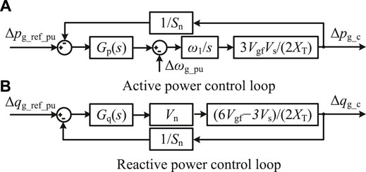
FIGURE 3. Block diagrams of the simplified active and reactive power control loops.
Assuming that Vgf ≈ Vs ≈ Vn and defining
Figure 4 shows the Bode diagrams of the system loop gains with different droop coefficients. When Dp = 0 the system loop gain has a 0° phase margin (PM), so the system is unstable in practice. When Dp = 50, the system is stable but only with a PM of 15°. With a certain inertia constant H and a required PM of ϕm, the value of Dp can be calculated by solving
where ωcrossover is the crossover frequency. The solution leads to
To obtain a PM of 45°, Dp should be 163, indicating that a 2% frequency change will cause a 326% active power change. Such a large Dp will easily overload the GFMCs when the grid frequency deviates from its nominal value.
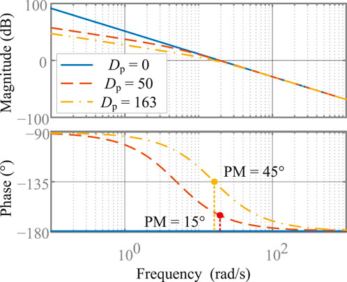
FIGURE 4. Bode diagrams of Gp_open(s) with droop control.
3.2 Sensitivity Analysis of Critical Eigenvalues
System stability is further analyzed by the detailed state-space model derived in section 3. Figure 5A depicts the eigenvalues of the state matrix A with Dp = 0, Dp = 50 and Dp = 163. Other system and control parameters can be referred to Table 1. Figure 5A highlights a pair of critical eigenvalues, whose real parts are positive when Dp = 0. This indicates that instability occurs when providing only virtual inertia by grid-forming converters.
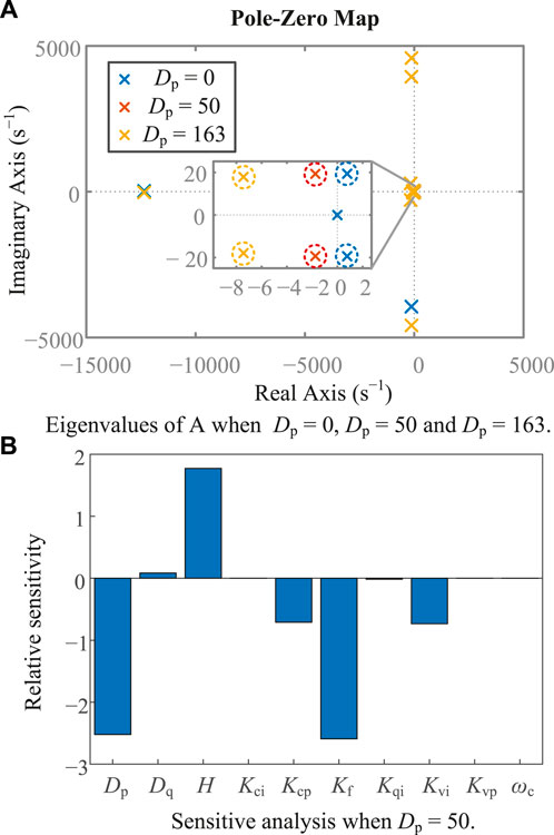
FIGURE 5. Eigenvalues and sensitivity analysis of A.
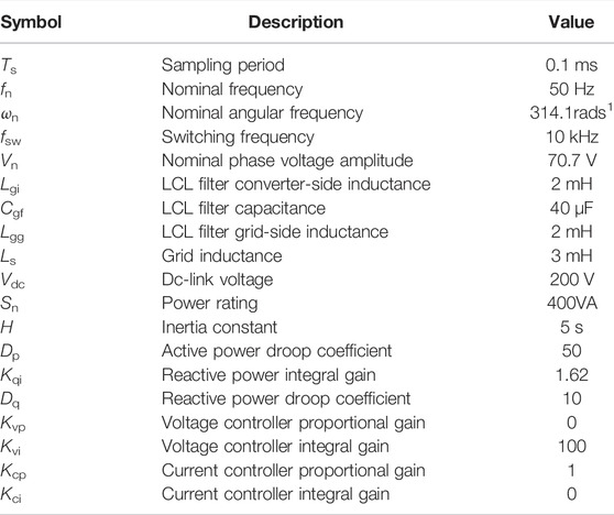
TABLE 1. System parameters and control parameters.
To determine the influence of each parameter on the critical poles, we conduct sensitivity analysis. The sensitivity of the nth eigenvalue to the kth parameter ρk takes the form of [5, 35]
where Φn and Ψn denote the left and right eigenvectors associated with the nth eigenvalue λn of A, respectively. As system stability is determined by the real parts of eigenvalues, they are more of interest. The positive sensitivity means that increasing the parameter will move the corresponding pole rightwards. Alternatively, the negative sensitivity suggests that increasing the parameter will move the corresponding pole leftwards.
Figure 5B shows the sensitivity analysis of the real parts of the critical poles in Figure 5A related to each control parameter when Dp = 50. It can be noticed that each control parameter influences the critical poles, especially for the droop coefficient Dp and the inertia constant H. Another dominant parameter is Kf, which will be introduced in the next section. The negative sensitivity of Dp indicates that increasing Dp will decrease the real part of the critical poles, and vice versa.
Figure 5A verifies the sensitivity analysis result of Figures 5B. According to Figure 5A with a fixed inertia constant H, when Dp = 50, the system is stable. However, the critical poles are very close to the imaginary axis, indicating that the respective stability margin is insufficient. Increasing Dp to 163 will improve stability yet cause a 326% additional steady-state power output under a 2% frequency deviation.
On the one hand, although droop control (or damping) improves stability, this is achieved at the expense of an additional power output (i.e. Δωo_puDp) as long as the frequency deviates from its nominal value. Notably, such an additional power output prevents droop control from being used in GFMCs without large energy storage, e.g. batteries. In addition, GFMCs delivering virtual inertia alone will be unstable without droop control (see Figure 5A). Therefore, a research gap exists, as will be filled up by the next section.
4 Stability Improvement Through the Proposed Lead Compensator
To stably emulate inertia via GFMCs without extra energy storage, this section proposes a novel lead compensator.
4.1 Design of the Proposed Lead Compensator
The proposed lead compensator is cascaded directly in the power controller and takes the form of
where Kf and ωc are the parameters of the lead compensator.
Inserting GL(s) into Figure 3 yields
According to the final value theorem (Franklin et al., 1994), when the grid frequency deviates from its nominal value, i.e. Δωg_pu(t) = A ⋅ 1(t) or Δωg_pu(s) = A/s, the steady-state power output is expressed as
Therefore, the proposed compensator can provide virtual inertia without causing steady-state output even under significant frequency deviations, which makes the energy storage capacity no longer important for the GFMC.
The simplified system loop gain of the APC loop with GL becomes
For GL(s) = (Kfs + ωc)/(s + ωc), the maximum phase boost is expected when (Franklin et al., 1994)
In our design, the major criterion lies in the maximum phase margin. This criterion can be further translated into
The solutions of 51 and 52 are
With Dp = 0 and Φm = 45°, the decisive control parameters are designed as Kf = 5.83 and ωc = 72.6rad/s1. The Bode diagrams of Gp_open with and without the lead compensator are shown in Figure 6. The phase margin is improved to 45° with the help of the proposed lead compensator. In addition, (48) indicates that the frequency deviation will not introduce any steady-state power output. As a result, the proposed lead compensator enables GFMCs to stably provide virtual inertia without adding extra energy storage.
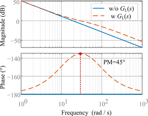
FIGURE 6. Bode diagrams of
4.2 Stability Analysis of Grid-Forming Converters With the Lead Compensator
Although the analysis result of the simplified APC loop is stable, the GFMC system stability also relates to other factors such as the interaction between the power control loop and inner control loops. As a result, the instability may be caused by other control and system parameters. To ensure the overall stability, we further tested the stability with the detailed small-signal model. When the lead compensator is applied, the small-signal state-space model of the designed APC and RPC becomes
where
The state Δx1 is introduced by the lead compensator. The expression of Ap&q2, Bp&q2, Cp&q2, and Dp&q2 can be found in Supplementary Appendix SA1.
Further, the overall state-space model corresponding to (29) is derived. In Supplementary Appendix SA1, A, B, C and D containing the dashed curved part describe the system model with the lead compensator.
Figure 7 plots the eigenvalues of the state matrix A with and without the lead compensator, where Kf = 5.83 and ωc = 72.6rad/s1. Recapping Figure 5A,B, we find that increasing Kf can move the critical poles leftwards, which is verified in Figure 7. The pole-zero map shows that the proposed lead compensator can improve system stability.
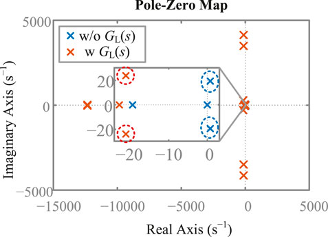
FIGURE 7. Eigenvalues of A with and without the designed lead compensator.
5 Simulation and Experimental Results
This section verifies the analysis and design of GFMCs with virtual inertia by simulations and experiments based on the schematic diagram shown in Figure 1.
5.1 Simulation Results
Figure 8 compares the active and reactive power responses of the small-signal model and the simulation under a 100 W active power reference step-up change of GFMCs. The close resemblance between the two cases verifies the correctness of the presented model.
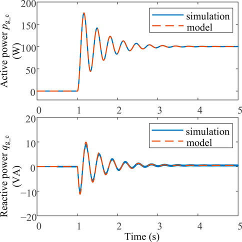
FIGURE 8. Active and reactive power responses of the small-signal model and simulation of the droop-controlled converters under a 100 W step-up active power reference change.
Figure 9 shows the step-up active power responses of GFMCs with different control parameters. As shown, delivering virtual inertia alone without any damping (i.e. Dp = 0 and Kf = 1) destabilizes the system. When Dp is increased to 50, the system is stabilized yet with slow dynamics, characterized by a large overshoot. In contrast, when the proposed lead compensator is activated (i.e. Dp = 0 and Kf = 5.83), the system is stabilized with satisfactory dynamics.
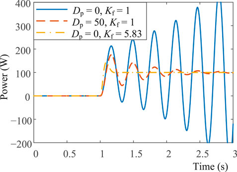
FIGURE 9. Simulated 100 W step-up active power responses of GFMCs with different parameters.
In Figure 10, the effectiveness of virtual inertia delivered by the GFMC is validated. In this case, the GFMC is tied to an SG, whose model incorporates a reheat steam turbine and a speed governor for frequency regulation. Notably, Hg and HGFMC represent the inertia coefficients of the SG and the GFMC, respectively. As observed from Figure 10, with the SG only, i.e. HGFMC (0 s) + Hg (5 s) = 5 s, the frequency nadir reaches 48.53 Hz, and the maximum RoCoF is 0.094 Hz s−1. When the GFMC contributes virtual inertia,i.e. HGFMC (5 s) + Hg (5 s) = 10 s, the frequency nadir and RoCoF are improved to 48.82 Hz and 0.047 Hz s−1, respectively. The delivery of virtual inertia improves the frequency nadir by 19.7%. In addition, we achieve a 50% improvement in the RoCoF. The response of the combination inertia HGFMC (5 s) + Hg (5 s) = 10 s is almost the same as the response with SG inertia Hg = 10 s only. As a result, the inertia provided by the proposed GFMC is almost identical to the SG inertia itself.
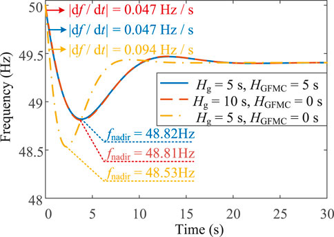
FIGURE 10. Simulated frequency responses of power systems under a 100 W (25%) step-up load change.
5.2 Experimental Results
We conducted experiments to verify the stability and the inertia enhancement of the proposed controller based on the system schematic diagram shown in Figure 1. The system parameters and the GFMC control parameters are shown in Table 1. Figure 11 displays the photo of the experimental platform. As seen, a VSM emulates the SG in experiments. The VSM and the GFMC are controlled by a dSPACE (Microlabbox) control platform and fed by two DC power supplies. An 8-channel oscilloscope (TELEDYNE LECROY: HDO8038) is employed to capture the experimental waveforms. The experimental results are shown in Figures 12–14.
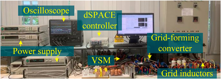
FIGURE 11. The experimental platform.
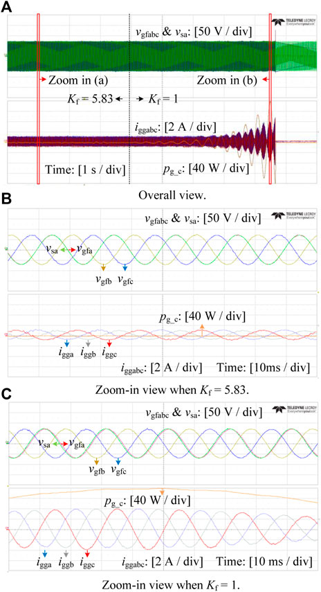
FIGURE 12. Experimental waveforms of the conveter voltages, grid voltages, converter output current and power when Kf =5.83 and Kf =1.
Figures 12A–C illustrate the stability enhancement of the proposed lead compensator. The VSM is designed as an ideal voltage source with a fixed frequency to emulate an infinite bus. The converter voltages vgfabc and the grid voltage vsa are plotted above. The currents iggabc and the power flowing from the GFMC to the VSM pg_c are plotted below. As observed in Figure 12A, when the lead compensator is applied (Kf = 5.83), the system is stable. The zoom-in view of the GFMC voltages vgfabc and VSG voltage vsa are illustrated in Figure 12B. The clean sinusoidal waveforms of the voltages and currents with low distortions show the rationality of the controller design. When the lead compensator is bypassed, i.e. Kf = 1, the currents iggabc and the transmitted active power pg_c start to oscillate and diverge, thus indicating that the system becomes unstable. The zoom-in view of the unstable condition is presented in Figure 12C. Figure 12C also reveals that the active power output changes with the phase difference between vsa and vgfa, which is a basic characteristic of GFMCs.
Figures 13, 14 validate the effectiveness of frequency response improvement by the proposed virtual inertia strategy. In this case, the VSM incorporates the models of the reheat steam turbine and the speed governor of an SG (Kundur 1994). The detailed implementation of the VSM can be found in (Fang et al., 2018a).
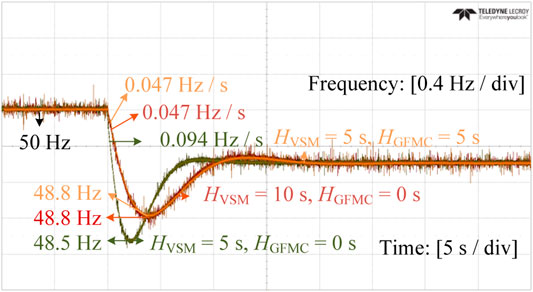
FIGURE 13. Experimental frequency responses under a 100 W (25%) step-up load change.
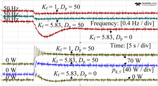
FIGURE 14. Experimental frequency and active power responses under a 100 W step-up load change.
Figure 13 shows the experimental frequency responses under a 100 W step-up load change, which corroborates Figure 10. It verifies that the proposed inertia enhancement strategy plays an identical role as synchronous inertia. In the case of a 5 s total inertia constant (i.e. HVSM + HGFMC = 5s), the frequency nadir and RoCoF reach 48.3 Hz and 0.094 Hz s−1, respectively. Increasing the total inertia constant to 10 s either by the VSM or the GFMC improves the frequency nadir by 0.3 Hz (or 20%) the RoCoF by 0.047 Hz s−1 (or 50%).
Figure 14 experimentally compares the proposed lead compensator with droop control. The inertia constants of the VSM and the GFMC are both designed to be 5 s. When the proposed lead compensator works alone (i.e. Kf = 5.83 and Dp = 0), the converter stably outputs active power with small oscillations, and the steady-state active power output is zero. In contrast, the GFMC with only droop control (i.e. Kf = 1 and Dp = 50) suffers from power oscillations. More importantly, the droop control stabilizes GFMCs at the expense of a continuous active power output, i.e. 70 W. In addition, it is possible to combine the proposed lead compensator and droop control (i.e. Kf = 5.83 and Dp = 50). As shown, this case features slightly better dynamics and a steady-state power output. Obviously, the proposed lead compensator is compatible with droop control.
6 Conclusion
This paper proposes flexible and distributed inertia emulation through existing grid-forming converters. We build a detailed state-space model, including the inner voltage and current loops as well as the outer power control loops. With the detailed model, the overall system stability and the interactions between the inner and outer control loops can be studied comprehensively. Based on the derived model, the subsequent sensitivity analysis reveals that grid-forming converters may possibly become unstable when they deliver distributed virtual inertia. Through the proposed lead compensator, we stabilize grid-forming converters. As compared with existing low-frequency oscillation damping methods, the proposed lead compensator enables stable inertia emulation without additional energy storage. In consequence, grid-forming converters can contribute power system inertia and improve the RoCoF and frequency nadir, as verified by simulation and experimental results. The future work includes the small-signal stability analysis and oscillation damping of large scale multi-GFMC systems.
Data Availability Statement
The original contributions presented in the study are included in the article/Supplementary Material, further inquiries can be directed to the corresponding author.
Author Contributions
HD and JF derived the model, did the analysis, proposed the methods, did experiments, and wrote the manuscript together.
Funding
This work was supported by Qilu Young Scholar Project 31400082163157 and Global Mainstream Dynamic Energy Technology Ltd. 1400022003.
Conflict of Interest
The authors declare that the research was conducted in the absence of any commercial or financial relationships that could be construed as a potential conflict of interest.
Publisher’s Note
All claims expressed in this article are solely those of the authors and do not necessarily represent those of their affiliated organizations, or those of the publisher, the editors, and the reviewers. Any product that may be evaluated in this article, or claim that may be made by its manufacturer, is not guaranteed or endorsed by the publisher.
Supplementary Material
The Supplementary Material for this article can be found online at: https://www.frontiersin.org/articles/10.3389/fenrg.2022.833387/full#supplementary-material
References
Ashabani, M., and Mohamed, Y. A.-R. I. (2014). Integrating Vscs to Weak Grids by Nonlinear Power Damping Controller with Self-Synchronization Capability. IEEE Trans. Power Syst. 29, 805–814. doi:10.1109/tpwrs.2013.2280659
Awal, M. A., Yu, H., Tu, H., Lukic, S. M., and Husain, I. (2020). Hierarchical Control for Virtual Oscillator Based Grid-Connected and Islanded Microgrids. IEEE Trans. Power Electron. 35, 988–1001. doi:10.1109/tpel.2019.2912152
Blaabjerg, F., Chen, Z., and Kjaer, S. B. (2004). Power Electronics as Efficient Interface in Dispersed Power Generation Systems. IEEE Trans. Power Electron. 19, 1184–1194. doi:10.1109/tpel.2004.833453
Blaabjerg, F., Teodorescu, R., Liserre, M., and Timbus, A. V. (2006). Overview of Control and Grid Synchronization for Distributed Power Generation Systems. IEEE Trans. Ind. Electron. 53, 1398–1409. doi:10.1109/tie.2006.881997
Chen, D., Xu, Y., and Huang, A. Q. (2017). Integration of Dc Microgrids as Virtual Synchronous Machines into the Ac Grid. IEEE Trans. Ind. Electron. 64, 7455–7466. doi:10.1109/tie.2017.2674621
D'Arco, S., and Suul, J. A. (2014). Equivalence of Virtual Synchronous Machines and Frequency-Droops for Converter-Based Microgrids. IEEE Trans. Smart Grid 5, 394–395. doi:10.1109/tsg.2013.2288000
Dong, S., and Chen, Y. C. (2018). A Method to Directly Compute Synchronverter Parameters for Desired Dynamic Response. IEEE Trans. Energ. Convers. 33, 814–825. doi:10.1109/tec.2017.2771401
Dong, S., and Chen, Y. C. (2017). Adjusting Synchronverter Dynamic Response Speed via Damping Correction Loop. IEEE Trans. Energ. Convers. 32, 608–619. doi:10.1109/tec.2016.2645450
Ebrahimi, M., Khajehoddin, S. A., and Karimi-Ghartemani, M. (2019). An Improved Damping Method for Virtual Synchronous Machines. IEEE Trans. Sustain. Energ. 10, 1491–1500. doi:10.1109/tste.2019.2902033
Fang, J., Li, H., Tang, Y., and Blaabjerg, F. (2018a). Distributed Power System Virtual Inertia Implemented by Grid-Connected Power Converters. IEEE Trans. Power Electron. 33, 8488–8499. doi:10.1109/tpel.2017.2785218
Fang, J., Li, H., Tang, Y., and Blaabjerg, F. (2019b). On the Inertia of Future More-Electronics Power Systems. IEEE J. Emerg. Sel. Top. Power Electron. 7, 2130–2146. doi:10.1109/jestpe.2018.2877766
Fang, J., Tang, Y., Li, H., and Li, X. (2018c). A Battery/ultracapacitor Hybrid Energy Storage System for Implementing the Power Management of Virtual Synchronous Generators. IEEE Trans. Power Electron. 33, 2820–2824. doi:10.1109/tpel.2017.2759256
Fang, J., Zhang, R., Li, H., and Tang, Y. (2019d). Frequency Derivative-Based Inertia Enhancement by Grid-Connected Power Converters with a Frequency-Locked-Loop. IEEE Trans. Smart Grid 10, 4918–4927. doi:10.1109/tsg.2018.2871085
Han, D., Fang, J., Yu, J., Tang, Y., and Debusschere, V. (2019). Small-signal Modeling, Stability Analysis, and Controller Design of Grid-Friendly Power Converters with Virtual Inertia and Grid-Forming Capability. IEEE Energ. Convers. Congress Exposition (Ecce), 27–33. doi:10.1109/ECCE.2019.8912534
Hirase, Y., Sugimoto, K., Sakimoto, K., and Ise, T. (2016). Analysis of Resonance in Microgrids and Effects of System Frequency Stabilization Using a Virtual Synchronous Generator. IEEE J. Emerg. Sel. Top. Power Electron. 4, 1287–1298. doi:10.1109/JESTPE.2016.2581818
Johnson, B. B., Sinha, M., Ainsworth, N. G., Dorfler, F., and Dhople, S. V. (2016). Synthesizing Virtual Oscillators to Control Islanded Inverters. IEEE Trans. Power Electron. 31, 6002–6015. doi:10.1109/tpel.2015.2497217
Khajehoddin, S. A., Karimi-Ghartemani, M., and Ebrahimi, M. (2019). Grid-supporting Inverters with Improved Dynamics. IEEE Trans. Ind. Electron. 66, 3655–3667. doi:10.1109/tie.2018.2850002
Lasseter, R. H., Chen, Z., and Pattabiraman, D. (2020). Grid-forming Inverters: A Critical Asset for the Power Grid. IEEE J. Emerg. Sel. Top. Power Electron. 8, 925–935. doi:10.1109/jestpe.2019.2959271
Liu, J., Miura, Y., and Ise, T. (2016). Comparison of Dynamic Characteristics between Virtual Synchronous Generator and Droop Control in Inverter-Based Distributed Generators. IEEE Trans. Power Electron. 31, 3600–3611. doi:10.1109/tpel.2015.2465852
Meng, X., Liu, J., and Liu, Z. (2019). A Generalized Droop Control for Grid-Supporting Inverter Based on Comparison between Traditional Droop Control and Virtual Synchronous Generator Control. IEEE Trans. Power Electron. 34, 5416–5438. doi:10.1109/tpel.2018.2868722
Piya, P., Ebrahimi, M., Karimi-Ghartemani, M., and Khajehoddin, S. A. (2018). Fault Ride-Through Capability of Voltage-Controlled Inverters. IEEE Trans. Ind. Electron. 65, 7933–7943. doi:10.1109/tie.2018.2803765
Qing-Chang, Z., Phi-Long, N., Zhenyu, M., and Wanxing, S. (2014). Self-synchronized Synchronverters: Inverters without a Dedicated Synchronization Unit. IEEE Trans. Power Electron. 29, 617–630. doi:10.1109/tpel.2013.2258684
Quan, X., Yu, R., Zhao, X., Lei, Y., Chen, T., Li, C., et al. (2020). Photovoltaic Synchronous Generator: Architecture and Control Strategy for a Grid-Forming Pv Energy System. IEEE J. Emerg. Sel. Top. Power Electron. 8, 936–948. doi:10.1109/jestpe.2019.2953178
REN21 (2020). Available at: https://www.ren21.net/.
Rocabert, J., Luna, A., Blaabjerg, F., and Rodríguez, P. (2012). Control of Power Converters in Ac Microgrids. IEEE Trans. Power Electron. 27, 4734–4749. doi:10.1109/tpel.2012.2199334
Taul, M. G., Wang, X., Davari, P., and Blaabjerg, F. (2020). Current Limiting Control with Enhanced Dynamics of Grid-Forming Converters during Fault Conditions. IEEE J. Emerg. Sel. Top. Power Electron. 8, 1062–1073. doi:10.1109/jestpe.2019.2931477
Wang, S., Liu, Z., Liu, J., Boroyevich, D., and Burgos, R. (2020). Small-signal Modeling and Stability Prediction of Parallel Droop-Controlled Inverters Based on Terminal Characteristics of Individual Inverters. IEEE Trans. Power Electron. 35, 1045–1063. doi:10.1109/TPEL.2019.2914176
Wang, X., Loh, P. C., and Blaabjerg, F. (2017). Stability Analysis and Controller Synthesis for Single-Loop Voltage-Controlled Vsis. IEEE Trans. Power Electron. 32, 7394–7404. doi:10.1109/tpel.2016.2632065
Wen, B., Dong, D., Boroyevich, D., Burgos, R., Mattavelli, P., and Shen, Z. (2016). Impedance-based Analysis of Grid-Synchronization Stability for Three-phase Paralleled Converters. IEEE Trans. Power Electron. 31, 26–38. doi:10.1109/tpel.2015.2419712
Wu, H., Ruan, X., Yang, D., Chen, X., Zhao, W., Lv, Z., et al. (2016). Small-signal Modeling and Parameters Design for Virtual Synchronous Generators. IEEE Trans. Ind. Electron. 63, 4292–4303. doi:10.1109/tie.2016.2543181
Xianyong, Z., Zijuan, G., Yaohong, H., Li, L., Weikuan, P., and Jian, C. (2021). Power Decoupling Control of MMC and Small-Signal Stability Analysis of AC/DC Distribution Network with Renewable Energy. Front. Energ. Res. 9. doi:10.3389/fenrg.2021.734797
Xin, H., Huang, L., Zhang, L., Wang, Z., and Hu, J. (2016). Synchronous Instability Mechanism of P-F Droop-Controlled Voltage Source Converter Caused by Current Saturation. IEEE Trans. Power Syst. 31, 5206–5207. doi:10.1109/tpwrs.2016.2521325
Xiong, L., Liu, X., Liu, Y., and Zhuo, F. (2020). Modeling and Stability Issues of Voltage-Source Converter Dominated Power Systems: A Review. Csee Jpes. doi:10.17775/cseejpes.2020.03590
Xiong, L., Zhuo, F., Wang, F., Liu, X., Chen, Y., Zhu, M., et al. (2016). Static Synchronous Generator Model: A New Perspective to Investigate Dynamic Characteristics and Stability Issues of Grid-Tied PWM Inverter. IEEE Trans. Power Electron. 31, 6264–6280. doi:10.1109/tpel.2015.2498933
Yuan, Z.-L., Xu, D., Jin, L., and Wang, H.-Z. (2021). Delay-Dependent Stability Analysis of Load Frequency Control for Power System with EV Aggregator. Front. Energ. Res. 9. doi:10.3389/fenrg.2021.771465
Zhang, L., Harnefors, L., and Nee, H.-P. (2011). Interconnection of Two Very Weak Ac Systems by Vsc-Hvdc Links Using Power-Synchronization Control. IEEE Trans. Power Syst. 26, 344–355. doi:10.1109/tpwrs.2010.2047875
Zhang, L., Harnefors, L., and Nee, H.-P. (2010). Power-synchronization Control of Grid-Connected Voltage-Source Converters. IEEE Trans. Power Syst. 25, 809–820. doi:10.1109/tpwrs.2009.2032231
Keywords: distributed generators, grid-forming converters, stability, state-space modeling, virtual inertia
Citation: Deng H and Fang J (2022) State-Space Modeling, Stability Analysis, and Controller Design of Grid-Forming Converters With Distributed Virtual Inertia. Front. Energy Res. 10:833387. doi: 10.3389/fenrg.2022.833387
Received: 11 December 2021; Accepted: 01 March 2022;
Published: 26 April 2022.
Edited by:
Shuqing Zhang, Tsinghua University, ChinaReviewed by:
Liansong Xiong, Nanjing Institute of Technology (NJIT), ChinaSridhar Seshagiri, San Diego State University, United States
Siqi Yu, Northern China Electric Power Research Institute, China
Copyright © 2022 Deng and Fang . This is an open-access article distributed under the terms of the Creative Commons Attribution License (CC BY). The use, distribution or reproduction in other forums is permitted, provided the original author(s) and the copyright owner(s) are credited and that the original publication in this journal is cited, in accordance with accepted academic practice. No use, distribution or reproduction is permitted which does not comply with these terms.
*Correspondence: Jingyang Fang , amluZ3lhbmdmYW5nQHNkdS5lZHUuY24=