 Safdar Raza1
 Hafiz Mudassir Munir
 Nouman Shafique
 Mohit Bajaj
 Mamdouh L. Alghaythi
- 1Department of Electrical Engineering, NFC Institute of Engineering and Technology, Multan, Pakistan
- 2Department of Electrical Engineering, Sukkur IBA University, Sukkur, Pakistan
- 3Department of Electrical and Electronics Engineering, National Institute of Technology Delhi, New Delhi, India
- 4Department of Electrical Engineering, College of Engineering, Jouf University, Sakaka, Saudi Arabia
The incorporation of distributed energy resources (DERs) into the electricity grid yields environmental, technical, and economic benefits. However, in addition to the benefits, the widespread use of DERs causes technical issues. Islanding is a big concern in terms of equipment protection and personnel safety, and it should be detected as soon as possible. The proposed approach employs a passive islanding detection technique based on reactive power (Q). The Q was chosen following a comparison of five other indices. Comparative analysis reveals that Q has the highest sensitivity and accuracy for islanding recognition when compared to all other observed parameters. Different case studies have been performed considering the worst-case scenario to check the working efficiency of the proposed scheme that simply distinguishes the islanding conditions from non-islanding conditions, which include load, motor, and capacitor switching, various types of fault switching, DG tripping cases, and weak grid contribution. The proposed strategy is straightforward, with quick execution and simple implementation in the MATLAB/SIMULINK environment on the IEEE 1547-2018 generic test system. With a small non-detection zone, islanding is detected in 0.038 s.
Introduction
Traditionally, a large amount of energy was produced at the generating end stations, and this generated energy at the power plants was then transmitted over long lines to the distribution and consumer ends. The trend is now toward distributed energy resources (DERs), which are utilized to generate power at lower levels. Solar systems, fuel cells, biomass, wind power plants, mini-hydro, biogas, tidal, and geothermal are examples of distributed generating resources. The energy produced by DERs is commonly referred to as distributed generation (DG). The DERs meet the majority of the load demand (Abd-Elkader et al., 2014). When a DG is integrated with the utility, the topological trends of the power system occur and the configuration of the system shifts from centralized to decentralized power generation (Manditereza and Bansal, 2016).
Positive effects are exerted on the power system by integrating the DG units with the utility. For example, DGs are environmentally friendly, and they avoid environmental contamination as compared to traditional energy generation resources, increase system flexibility, reduce power losses, and improve system efficiency (Manikonda and Gaonkar, 2019). However, along with the benefits, technical challenges arise, such as system synchronization issues, stability, system security, system upgradability, diversity, system reliability, false tripping, islanding, safety, and voltage regulation (Abd-Elkader et al., 2014; Manditereza and Bansal, 2016; Mishra et al., 2019). Among all of the technical challenges, islanding is a big concern in this case.
In an islanding condition, the utility’s supply to the load is cut off, while the load continues to receive power from the DG. Islanding is a common unintended occurrence that is dangerous not only to the power quality and system stability but also to the personnel on the site. As a result, in order to increase the performance of DERs, it is necessary to detect the moment when islanding occurs. According to the IEEE standard (IEEE-STD 1547), islanding should be identified within 2 s with no additional time delay (IEEE Standard Association, 2018).
Many researchers have presented islanding detection approaches, which are divided into two categories: remote and local techniques. Local techniques measure parameters at the DG side, whereas remote methods measure parameters at the utility side. The fundamental parameter for evaluating the performance of the islanding detection method (IDM) is the non-detection zone (NDZ). The non-detectable islanding zone is defined as the area where the islanding condition is not detected (Abd-Elkader et al., 2014; Manikonda and Gaonkar, 2019; Mishra et al., 2019).
In the case of remote methods, communication links are required for parameter observation between the utility and the DG. The benefits of these methods include high reliability and zero NDZ. But the high implementation cost is a major drawback (Papadimitriou et al., 2015; Karimi et al., 2016). The most commonly used remote techniques are power line carrier communication (PLCC) and supervisory control and data acquisition (SCADA) (Karimi et al., 2016).
Local methods are classified into three further groups, known as active, hybrid, and passive methods. In passive methods, the variation of parameters (voltage, frequency, total harmonic distortion, current, etc.) of a power system is monitored at the point of common coupling (PCC) (Manikonda and Gaonkar, 2019). The working principle of the local methods depends upon the trip signal of the relay to the circuit breaker of DG when the measured parameters at the PCC exceed the predefined threshold value (Manikonda and Gaonkar, 2019; Mishra et al., 2019). The benefits of the passive methods are their negligible impact on power quality and that they are easy to implement (Bayrak, 2015; Bayrak and Kabalci, 2016). Passive methods are unaffected by multi-inverter operation, independent of any type of DER used, and do not impact the distribution system (Bayrak, 2015; Bayrak and Kabalci, 2016; Mishra et al., 2019). However, the difficulty in selecting the threshold value and the large NDZ are the issues with these methods (Pinto and Panda, 2015; Bayrak and Kabalci, 2016). Passive methods that are commonly used are voltage phase jumps, total harmonic distortion (THD), under- and over-voltage, under- and over-frequency, power rate of change, and frequency methods (Manikonda and Gaonkar, 2019).
Some of the passive schemes use signal processing and artificial intelligence techniques combined to reduce the non-detection zone (NDZ) and to improve the performance of the islanding detection schemes. Some of the techniques classified in the literature (Faqhruldin et al., 19922014; Mohamad et al., 2011; Aljankawey et al., 2012; Heidari et al., 2013; Abd-Elkader et al., 2014; Khamis et al., 2015) based upon artificial intelligence include decision trees, artificial neural networks, random forest classifiers, naïve Bayesian classifiers, and fuzzy logic, whereas the others proposed the techniques based upon signal processing in the literature (Shyh-Jier Huang and Huang, 2001; Jang and Kim, 2004; Mohamad et al., 2011; Heidari et al., 2013; Al Hosani et al., 2015; Gupta et al., 2015; Bakhshi and Sadeh, 2016) which include S-transform, T-transform, wavelet transform, and fast Fourier transform. In signal processing schemes, by transforms, we have to analyze the signals and abstract the hidden information which was not readily present in the raw signal.
In the active methods, the perturbations are injected into the parameters of the system to monitor the disturbances occurring due to abnormal conditions. No significant changes occur during the grid-connected state, while significant alterations in parameters occur during the islanding condition. As compared to the passive methods, these methods have nearly zero non-detection zone (NDZ) (Abd-Elkader et al., 2014; Papadimitriou et al., 2015; Bayrak and Kabalci, 2016). The perturbations injected into the system create power quality issues in active techniques (Abd-Elkader et al., 2014; Papadimitriou et al., 2015). A detailed study of the active methods is described by Al Hosani et al. (2015), Bayrak (2015), Gupta et al. (2015), Pinto and Panda (2015), Bakhshi and Sadeh (2016), Bayrak and Kabalci (2016), and Karimi et al. (2016). In the study by Valsamas et al. (2018), Voglitsis et al. (2018), Voglitsis et al. (2019a), and Voglitsis et al. (2019b), some recent active islanding detection methods are developed for inverter-based DG considering high penetration of renewables and weak contribution of a grid. These techniques have the advantage of multi-inverter applicability in power systems and zero NDZ. However, slight issues of power quality and complex algorithm techniques are still present in these methods. Besides these issues, various islanding and non-islanding cases at different mismatches are not anticipated. An active islanding method for inverter-based DG has been developed by Bakhshi-Jafarabadi et al. (2020). Fast tripping time and insignificant NDZ are the key advantages of this method. However, the implementation cost is slightly higher than that of passive methods. In the study by Sivadas and Vasudevan (2019), an active technique has been proposed for multiple inverter operations considering zero NDZ and without power quality issues. However, the algorithm is complex, and the use of a GPS module makes the scheme non-economical. The voltage negative feedback (VNF) algorithm–based active method for a grid-connected photovoltaic system has been presented by Bakhshi-Jafarabadi and Sadeh (2020). This method has the advantage of zero NDZ, fast tripping time, and no power quality problems. The algorithm complexity is kept as low as possible in this scheme. However, it is not suitable from an economical perspective. The merging of the two techniques (active and passive) is known as a hybrid technique. It includes the characteristic features of both active and passive methods. A brief discussion of this method is presented by Mishra et al. (2019).
It is perceived that, to observe the islanding detection techniques, the researchers have studied both the rate of change of the parameters and indices in the literature. 16 different rates of change have been studied by Raza et al. (2016). In this study, the passive approach is proposed for islanding detection, and the rate of change of frequency over reactive power (ROCOFOQ) is considered the most effective parameter for performance evaluation. The fastness of the proposed technique is its benefit, but it has the drawback of small NDZ. Indices have not been monitored and analyzed in this research. In the study by Raza et al. (2021), for improving the efficiency of the system, six different indices have been considered, while the method used in this research is based upon the mathematical morphology which is a passive IDM. The most sensitive parameter in this study is found out to be the reactive power in terms of better islanding detection. The method proposed is simple and has fast execution, but a large NDZ is still its major drawback. The variation in frequency and voltage indices has been analyzed by Abd-Elkader et al. (2018) to detect the islanding scenario. The technique proposed in this paper has the benefit of zero NDZ, but it offers a complex algorithm and complex mathematical calculations. In some research studies, only two indices have been considered for islanding detection study like the voltage/current of a negative sequence in which the wavelet algorithm is utilized by Taheri Kolli and Ghaffarzadeh (2020), voltage/phase angle of a positive sequence (Mishra et al., 2020), and transient index voltage/angle of a positive sequence superimposed on the current (Nale et al., 2019). These techniques have almost zero NDZ and offer huge accuracy, but the algorithm becomes complex because of the usage of the two indices. A passive method has been studied by Xie et al. (2020) using dynamic behavior of the load conditions. The NDZ of this method is very small and has fast tripping time. However, the algorithm has extensive mathematical complexity. A fast and reliable passive method with a negligible NDZ for inverter-based DG has been designed using micro-phasor measurement units (Karimi et al., 2021). These units measure the rate of change of voltage (ROCOV) and magnitudes of the ratio of voltage and current at the point of common coupling (PCC). However, multiple parameters make the algorithm slightly complex. In the study by Xie et al. (2021), the accuracy of the passive method has been improved considering the adaptive threshold. The rate of change of power factor angle is employed as the islanding detection index. This method has considered the dynamic behavior of load and offers a smaller NDZ. However, choosing an adaptive threshold by analyzing the relationship between the reactive power and the resonant frequency of load after islanding occurrence makes the scheme complex.
After a detailed literature review on islanding detection methods, we have found that most of passive islanding detection algorithms are complex and lengthy. Some of the methods have large computational burden, and some of them have used multiple combinations of parameters. The main focus of researchers was the performance analysis of parameters considering different rates of changes for better results. However, the performance analysis of indices is not anticipated in a comprehensive manner. In this paper, a methodology is developed in accordance with the IEEE 1547 standard test network.
The main contributions of the proposed approach are as follows:
• Performing a comprehensive performance analysis of parameters to find the most sensitive parameter that can easily distinguish islanding from other disturbances
• Obtaining a most suitable power system index (Q) that can easily detect minor variation
• Developing a simplest, accurate, sensitive, and fast detection method for islanding situation
• Reduced detection time
• Insignificant NDZ
• Testing the method efficacy under various load quality factors Qf
• Checking the efficacy of the proposed approach considering various non-islanding events, specifically the weak contribution of a grid
This paper is structured in the following way: System demonstration is presented in System Demonstration and Analysis of Passive Indices, and Analysis of Passive Indices discusses the performance analysis of passive systems. The proposed methodology and validation to select the sensitive indices are presented in Protection Strategy. Simulation results are discussed in Simulation Results. The NDZ of the proposed scheme, discussion, and conclusion are given in NDZ of Proposed Scheme, Discussion, and Conclusion, respectively.
System Demonstration
In this work, the power system comprises of two doubly fed induction generators (DFIGs) in parallel that are having the capacity of 1 MW each, a parallel RLC load, and a utility grid. Transformers of the grid and wind farms are connected altogether to an 11 KV voltage level and the frequency of a 50 Hz distribution system. Circuit breakers are attached at the utility and the DG side named “C.BGrid” and “C.BDG,” respectively. A wound rotor induction generator is used in DFIGs, and IGBTs are used as semiconductor devices for the AC–DC and DC–AC conversions. The rotors are provided with the variable frequency by the AC–DC–AC converters, whereas there is the direct link of a stator winding with a power grid. For the validation of proposed passive indices, the IEEE 1547 standard test network (Xie et al., 2020) is used as depicted in Figure 1. The summary of IEEE 1547 recommended standard limits is tabulated in Table 1 (Mishra et al., 2019). The characteristics and performance of islanding recognition techniques mainly depend upon the load type. That is why the IEEE STD test network recommends using parallel RLC load as it is complex compared to other loads.
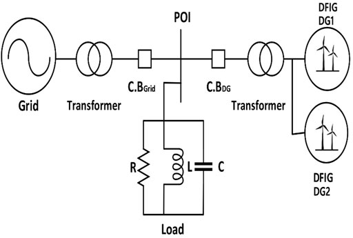
FIGURE 1. IEEE 1547 standard test network.
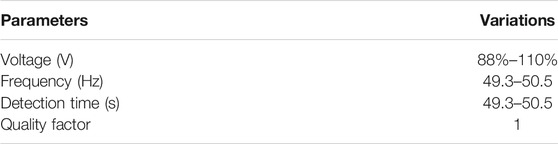
TABLE 1. IEEE 1547 recommended standards.
Analysis of Passive Indices
Five various passive islanding detection parameters such as active power, frequency, power factor, voltage, and reactive power are analyzed in this study according to power mismatch presented in Table 2. For the comparative analysis of passive indices, we have performed various islanding and non-islanding events in accordance with the IEEE 1547 standard test network. We have enlisted the events briefly here.

TABLE 2. Testing scenarios.
Islanding Events
Islanding events are as follows:
a. Balanced islanding events
• When active and reactive powers of the grid are the same and kept low as much as possible (Pmin, Qmin)
• When active and reactive powers of the grid are the same and kept high as much as possible (Pmax, Qmax)
b. Unbalanced islanding events
• When the active power of the grid is less than the grid reactive power (Pmin, Qmax)
• When the active power of the grid is greater than the grid reactive power (Pmax, Qmin)
In general circumstances of islanding, it is easy to detect islanding operation in unbalanced islanding situation as compared to balanced situation. This is because either grid active power or reactive power plays a dominant role in creating large disturbances or variation in system parameters. However, when balanced islanding situation occurs, grid active power and reactive power become equal in magnitude and difficult to create minor disturbances or variation in other system parameters. We have observed these situations in simulations. Therefore, we have considered these two cases (Pmin, Qmin) as small power mismatch (S.M) and (Pmax, Qmax) as large power mismatch (L.M) as worst possible cases for analysis.
Non-Islanding Events
Non-islanding events considered balanced in this study are as follows:
a. Load injection at small mismatch (L.I-S.M)
b. Load ejection at small mismatch (L.E-S.M)
c. Capacitor injection at small mismatch (C.I-S.M)
d. Capacitor ejection at small mismatch (C.E-S.M)
e. Motor injection at small mismatch (M.I-S.M)
f. Motor ejection at small mismatch (M.E-S.M)
g. Fault operation at small mismatch (F-S.M)
h. DG tripping at small mismatch (D.T-S.M)
i. DG tripping at small/large mismatch (D.T-S.M/L.M)
j. Weak contribution of a grid at small mismatch (W.G-S.M)
Weak contribution of a grid has a significant impact on the protection strategy when islanding situations occur. This case has not been anticipated in the previous works yet. When this situation occurs, the protection method should recognize this as a non-islanding event. This case is simulated in detail in Weak Grid Contribution.
The measured values of all passive indices (voltage, frequency, active power, reactive power, power factor) in Figures 2A–E are the absolute mean values against various events (load switching, capacitor switching, motor switching, fault switching, DG tripping, and weak grid). For each parameter, we have performed various events mentioned above one by one and recorded their magnitude to compare them against all events. For the selection of parameter, islanding events’ magnitudes should be different (greater than or lower than) from those of non-islanding events. After careful observation of Figures 2A–E, we have noted that some of islanding and non-islanding scenarios have the same magnitude, and it is not clearly said that whether it is an islanding operation or a non-islanding operation. However, the reactive power (Q) in Figure 2D shows the different magnitudes of islanding events against non-islanding events. The magnitudes of islanding events are less than those of non-islanding for reactive power. This forms a basic principle of our protection strategy.
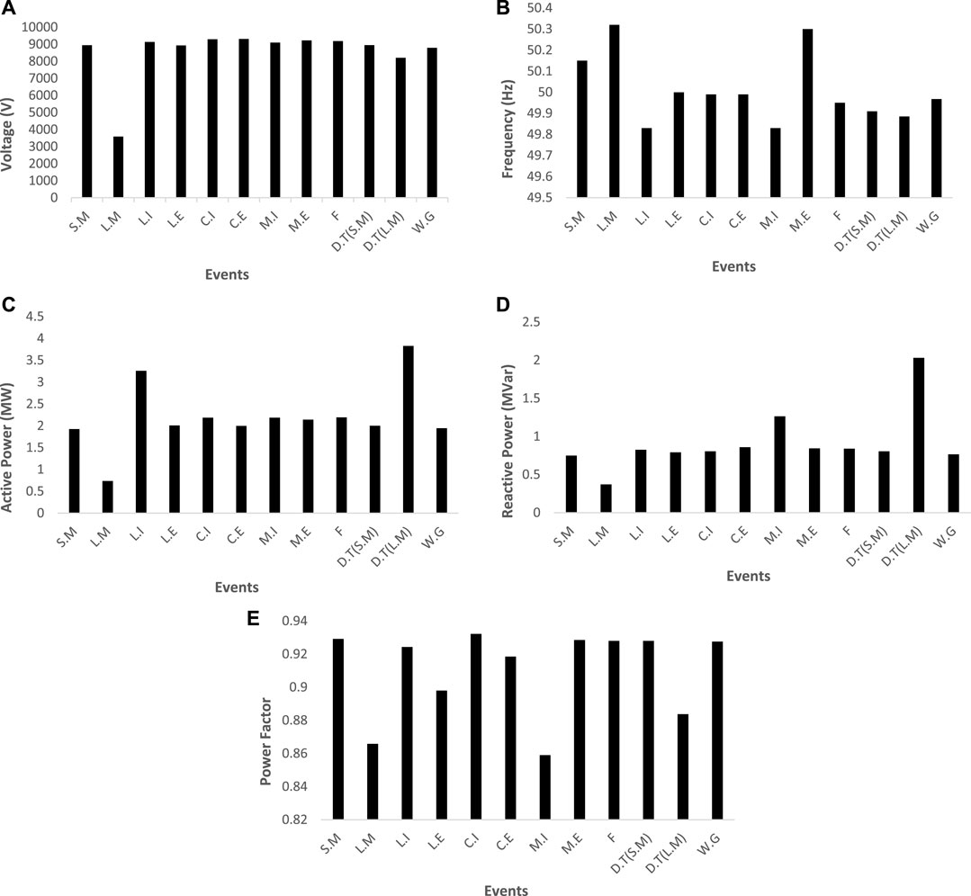
FIGURE 2. Parameters vs. events. (A) Voltage. (B) Frequency. (C) Active power. (D) Reactive power. (E) Power factor.
As we have considered various indices just like V(volts), f(Hz), P(W), Q(Var), P.F, all of them have different nature of magnitudes along with SI units. It is not possible to compare all the indices with different SI units for the purpose of sensitivity. We have also carefully noticed in the literature review that indices have not been compared on one scale of magnitude. However, rates of changes have been compared on the same magnitude scale. Raza et al. (2016) found df/dQ due to the highest sensitivity (magnitude) shown as compared to other rates of changes. All rates of changes have unit-less magnitudes, so they are comparable in one scale. Raza et al. (2021) performed MM-based technique for islanding detection considering indices with different SI units. They found reactive power on the basis of sensitivity by comparing islanding events with non-islanding. The magnitude of islanding events is greater than that of non-islanding events for reactive powers only. Thus, we have compared sensitivity of each separate index (Figure 2) by their islanding and non-islanding operations to find that which operation has a higher magnitude.
The main aim of performance analysis of passive indices is to find the most suitable index that can detect minor disturbances efficiently in the worst possible islanding situation. The selected parameter (reactive power) as compared to the remaining other presented indices easily shows the performance on keeping the active and reactive power mismatches as lower as possible. Furthermore, the NDZ and the detection time of the reactive power are very small compared to other analyzed indices in worst possible power mismatch cases. The reactive power has the ability to clearly distinguish islanding from non-islanding operations. However, the magnitudes of all performed events of other passive indices other than Q are intermixing that results in an unclear picture of events as can be observed in Figures 2A–E. Thus, the reactive power (Q) has been selected after a comprehensive performance analysis.
Protection Strategy
From the comparative analysis of five different indices, it has been observed that the Q shows the best possible results which separate the islanding and non-islanding conditions. The basic principle of the passive method is to measure passive (on-site) parameters (e.g., voltage, frequency, THD) at the point of common coupling (PCC) upon the occurrence of islanding situation. In the proposed method, the parameter minimum absolute mean values for all islanding and non-islanding cases are taken into account and recorded within five cycles. The threshold value of a proposed parameter is selected after the performance analysis of passive indices considering various islanding and non-islanding events in the worst available cases. The threshold has been selected via a hit and trial process.
The performance analysis of passive parameters helps in the selection of the threshold. In the proposed technique, magnitudes of non-islanding events are greater than magnitudes of islanding events of Q as compared to other analyzed indices. Thus, the selected parameter clearly distinguished islanding events from non-islanding events. Whenever the magnitude of the selected parameter becomes lower than the threshold, the proposed scheme gets activated and sends a trip signal to the breaker of a DG unit. The whole operating principle can be analyzed by Eq. 1. The flowchart of the proposed strategy is shown in Figure 3:
where (Q)measured is the minimum absolute measured value and (Q)threshold is the already defined threshold value which defines a specific value to differentiate the islanding and non-islanding events.
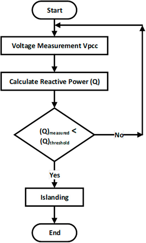
FIGURE 3. Flowchart of the proposed scheme.
During normal operation of a power system, both DGs and grid delivered power to the load. DGs supplied almost complete power to the respective load, whereas load obtained remaining power from the grid. However, during the islanding mode, the power consumption of RLC load is entirely dependent on DGs. The power consumption of RLC load is represented by the following equations (Bakhshi-Jafarabadi et al., 2020):
where f and VPCC are the frequency and voltage at the point of common coupling (PCC), while RLC shows the resistance, inductance, and capacitance of RLC load. Eqs 2–4 show the representation of active and reactive powers of load at the PCC. Power mismatch during the islanding condition depends upon DG and load profiles (Bakhshi-Jafarabadi et al., 2020).
Simulation Results
The validation of the planned work is done by using the IEEE 1547 standard network as depicted in Figure 1. After the power system gets stable, the islanding and false tripping conditions are analyzed at 5 s. The threshold value is defined to be 0.76 MVar for this simulation study. The value of threshold has been opted in such a manner that it may clearly distinguish the various simulation cases easily. In the proposed work, the selected threshold value is represented in a manner that it trips the CB of the DG when the value of Q is less than the threshold value, while the non-islanding scenarios have large values than the threshold value.
Islanding at Power Mismatch (Pmin, Qmin)
In this situation, the active and reactive power values of DGs are 2.01 MW and 0.82 MVar, respectively, while the rest of the electricity is supplied by the utility having a minimum value of 0.14 MW active power and minimum value of 0.11 MVar reactive power in order to energize the load which is having 2.14 MW active power and 0.84 MVar reactive power. The response of this condition is shown in Figures 4A, B along with the trip signal. The measured Q in this case comes out to be 0.74 MVar which is smaller than the preset threshold and is representing the islanding condition. The scheme gets initiated and sends a trip signal to the CB of the DFIG and disconnects the DG from the load. The detection time of this condition is 0.0322 s.
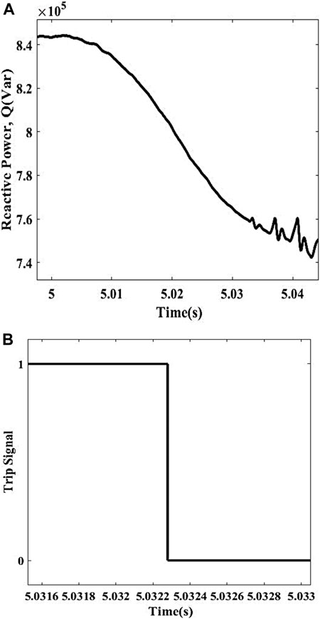
FIGURE 4. Islanding event. (A) Islanding at Pmin, Qmin. (B) Detection time.
Islanding at Power Mismatch (Pmax, Qmin)
For this case, the active and reactive power values of DGs are 2.01 MW and 0.82 MVar, respectively, though the rest of the electricity is supplied by the utility having a maximum value of 2.00 MW active power and minimum value of 0.18 MVar reactive power in order to energize the load which is having 4.00 MW active power and 0.78 MVar reactive power. The response of this condition is shown in Figures 5A, B along with the trip signal. The measured Q in this case comes out to be 0.638 MVar which is smaller than the preset threshold and is representing the islanding condition. The scheme gets operated and sends a trip signal to the CB of the DFIG and disconnects the DG from the load. The detection time of this condition is 0.0135 s.
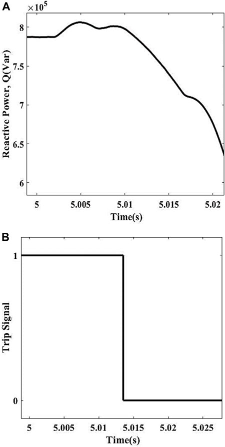
FIGURE 5. Islanding event. (A) Islanding at Pmax, Qmin. (B) Detection time.
Islanding at Power Mismatch (Pmin, Qmax)
In this event, the active and reactive power values of DGs are 2.10 MW and 0.46 MVar, respectively, whereas the rest of the electricity is supplied by the utility having a minimum value of 0.76 MW active power and maximum value of 3.30 MVar reactive power in order to energize the load which is having 1.29 MW active power and 3.28 MVar reactive power. The response of this condition is shown in Figures 6A, B along with the trip signal. The measured Q in this case comes out to be 0.3 MVar which is smaller than the preset threshold value and is representing the islanding condition. The scheme gets initiated and sends a trip signal to the CB of the DFIG and disconnects the DG from the load. The detection time of this condition is 0.0380 s.
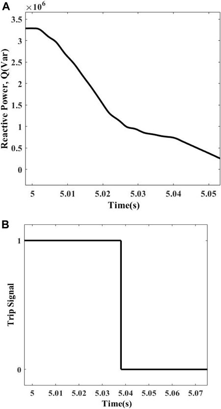
FIGURE 6. Islanding event. (A) Islanding at Pmin, Qmax. (B) Detection time.
Islanding at Power Mismatch (Pmax, Qmax)
In this scenario, the active and reactive power values of DGs are 2.07 MW and 0.51 MVar, respectively, whereas the rest of the electricity is supplied by the utility having 2.0 MW active power and 2.0 MVar reactive power to energize the load which is having 4.04 MW active power and 2.11 MVar reactive power. The response of this condition is shown in Figures 7A, B along with the trip signal. The measured Q in this case comes out to be 0.37 MVar which is smaller than the preset threshold value and is representing the islanding condition. The scheme gets operated and sends a trip signal to the CB of the DFIG and disconnects the DG from the load. The detection time of this condition is 0.0249 s.
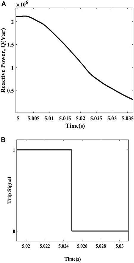
FIGURE 7. Islanding event. (A) Islanding at Pmax, Qmax. (B) Detection time.
Load Switching
An RLC load having the ratings of 1.1 MW and 0.35 MVar and 0.6 MW and 0.45 MVar is attached in parallel and removed from the system, respectively, to check the behavior of the proposed technique. The Qmeasured for this case comes out to be 0.82 MVar in case of attachment of load, while the removal of load gives 0.79 MVar values. Both the values are greater than the preset threshold value, so the scheme considers it a non-islanding condition and does not operate. The response of this condition is depicted in Figures 8A, B.
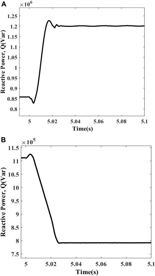
FIGURE 8. Load switching. (A) Load injection. (B) Load ejection.
Capacitor Switching
A capacitor bank having the rating of 0.05 MVar is attached and removed from the system to check the response of the proposed technique. The Qmeasured for this case comes out to be 0.805 MVar in case of attachment of capacitor bank, while the removal of capacitor bank gives 0.858 MVar values. Both the values are greater than the preset threshold value, so the scheme considers it a non-islanding condition and does not operate. The response of this condition is depicted in Figures 9A, B.
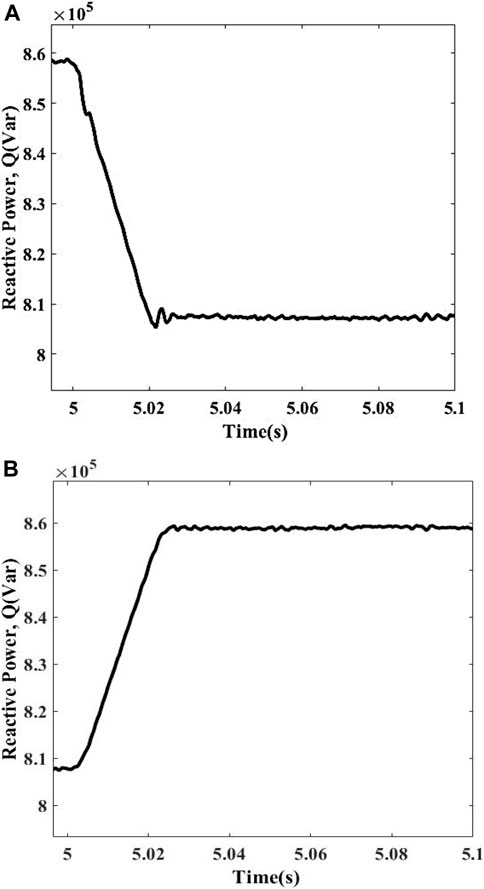
FIGURE 9. Capacitor switching. (A) Capacitor injection. (B) Capacitor ejection.
Motor Switching
A motor having the rating of 50hp is attached and removed from the system in order to check the behavior of the proposed technique. The Qmeasured for this case comes out to be 1.26 MVar in case of attachment of motor, while the unloading of motor gives 0.84 MVar values. Both the values are greater than the preset threshold value, so the scheme considers it a non-islanding condition and does not operate. The response of this condition is depicted in Figures 10A, B.
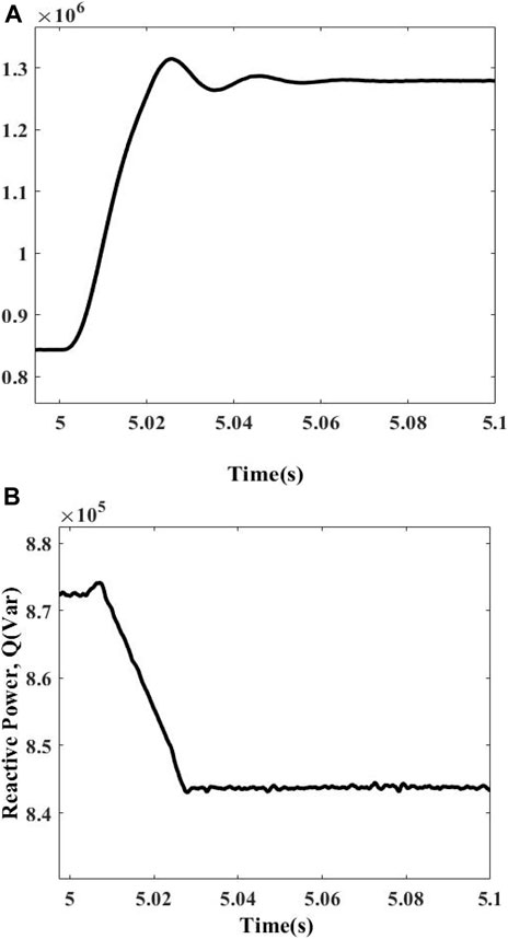
FIGURE 10. Motor switching. (A) Motor injection. (B) Motor ejection.
Fault Switching
To check the response of faults, various fault types are introduced in the system and are analyzed. The faults include the following:
• Three-phase fault (ABC)
• Three phase to ground fault (ABCG)
• Two-phase fault (AB)
• Two phase to ground fault (ABG)
• Single line to ground fault (AG)
A fault having a resistance of 200Ω is introduced for a short interval of 0.04 s. The Qmeasured comes out to be as follows:
• ABC = 0.839 MVar
• ABCG = 0.839 MVar
• AB = 0.81 MVar
• ABG = 0.79 MVar
• AG = 0.82 MVar
All the fault values are greater than the preset threshold value, so the system efficiently differentiates the scenario from the islanding condition and does not operate the scheme. The responses of these various faults are shown in Figures 11A–E.

FIGURE 11. Fault operation. (A) Three-phase fault. (B) Three phase to ground fault. (C) Double line to ground fault. (D) Single line to ground fault. (E) Two-phase fault.
DG Tripping at Various Power Mismatches
This case represents a situation of DG tripping when one of the DG units is separated from the power system due to any reason, whereas the remaining DG is still energizing the load. Thus, the event is tested in order to check the working of the proposed technique under currently imposed circumstances. The tripping of DG is initiated at 5 s. The measured value of Q is recorded at power mismatches of (Pmin, Qmin) and (Pmax, Qmax) of 0.805 MVar and 2.03 MVar which are greater than the threshold. So, the proposed method easily identifies this case as a non-islanding situation. The response of this event is shown in Figures 12A, B.
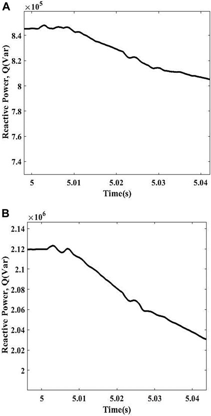
FIGURE 12. DG tripping. (A) DG tripping at Pmin, Qmin. (B) DG tripping at Pmax, Qmax.
Weak Grid Contribution
The proposed technique is further tested considering weak contribution from a grid. Weak grids create significant variations in parameters (voltage, current, etc.) at the PCC. Sometimes abnormal conditions occur due to the fault appearance at the grid side. This fault could be due to the lightning strike, feeder lines’ short circuit, beaker failure, etc. Four types of variations are introduced in the grid to check the efficacy of the proposed algorithm. Types of variations are tabulated in detail in Table 3. These four types of signals are injected at the PCC from the grid side. The measured values of Q recorded for table of time–amplitude pairs, modulation, ramp, and step are 0.7645 MVar, 0.85 MVar, 0.819 MVar, and 0.845 MVar which are still greater than the threshold. The behavior of this event is shown in Figures 13A–D. Hence, the proposed method recognizes this as a non-islanding event. Simulation parameters for this case are tabulated in Table 3.

TABLE 3. Simulation parameters for time-variation amplitude with different types.
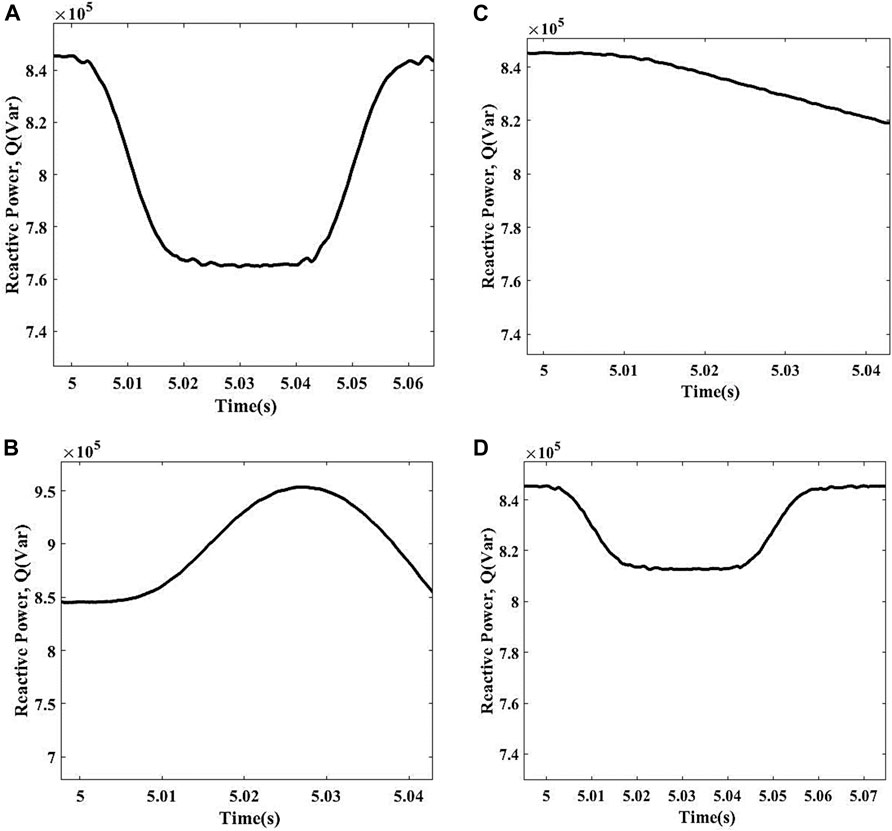
FIGURE 13. Weak grid condition. (A) Time–amplitude. (B) Modulation. (C) Ramp. (D) Step.
Different Load Quality Factors
The worst case to verify the performance of the islanding detection method is to keep the active and reactive power mismatches as small as possible. The load quality factor of Qf = 2.5 and Qf = 1.8 regarding the IEEE standard has been employed to depict the performance of the proposed method, respectively. This high-quality factor of load can result in a large NDZ for the conventional method. For the proposed method, islanding and non-islanding operations are tested at a power mismatch of 0.1 MW and 0.1 MVar between the DG and the load. The values of R, L, and C for different Qf are
The response of Qmeasured considering both scenarios is tabulated in Table 4. The Qmeasured varies at different quality factors as shown in Table 4. However, it is quite clear that Q has the ability to easily discriminate islanding events from non-islanding scenarios.
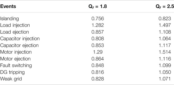
TABLE 4. Qmeasured (MVar) for different quality factors.
Analysis of NDZ in Case of Minimum PGRID and QGRID
Practically, the NDZ of the islanding detection approach can never be zero. The NDZ of the islanding method mainly depends upon the type of DG, types of loads, and design of a strategy in accordance with the standard test or benchmark system employed. As far as our protection strategy is concerned, we kept the NDZ as low as possible for better performance of the result and accuracy. To present the worst possible case, we kept PGRID and QGRID to be 0.09 MW and 0.09 MVar, respectively. We performed this special analysis to check method effectiveness. The analysis details are tabulated in Table 5. The proposed method easily detects the islanding situation with a detection time of 0.0391 s. The measured value of Q in this case comes out to be 0.8724 MVar. The response of the method under this condition is shown in Figures 14A, B.
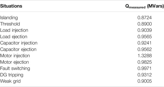
TABLE 5. Qmeasured for various events.
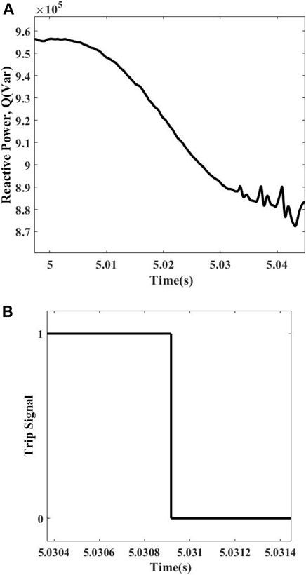
FIGURE 14. Minimum NDZ analysis. (A) Qmeasured at minimum NDZ for islanding. (B) Detection time.
NDZ of Proposed Scheme
One of the key factors to assess the performance efficacy of the islanding detection method is the NDZ. This is a portion where islanding strategies are not able to diagnose islanding situations. For active power NDZ, it is found by Zeineldin et al. (2006) that
where ΔP is the active power mismatch, V and I are the rated voltage and current, respectively, ΔV is the voltage deviation, and cos φ is the power factor.
The permissible voltage variation in the distribution network under study is 0.9 pu and 1.1 pu. Considering these voltage levels, the deviation range ΔV is between −0.1 and 1.1, respectively. The NDZ region of active power mismatch ΔP studied for this system is +0.20 MW and −0.20 MW.
For reactive power NDZ, it is found by Zeineldin et al. (2006) that
where V is the rated voltage, fn is the nominal frequency, Δf is the frequency deviation, and ωn = 2 × π × f.
For the power system under study, the permissible range for frequency variation Δf lies between −0.5 Hz and 0.5 Hz. Thus, the NDZ of the power system regarding reactive power mismatch is 0.2128 MW and −0.2192 MW. Simulation results also tell that when power mismatch is 0.09 MW and 0.09 MVar, the proposed technique operates proficiently. Compared to conventional techniques of OF/UF (over-frequency/under-frequency) and OV/UV (over-voltage/under-voltage), the proposed method improves the accuracy and gives an insignificant NDZ as shown in Figure 15.
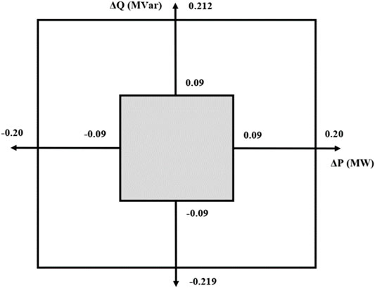
FIGURE 15. NDZ plot.
The NDZ size is determined on comparing the proposed method with the conventional passive technique (OF/UF and OV/UV) analytically. Graphically, ΔP is plotted on the x-axis, whereas ΔQ is plotted on the y-axis, respectively. This is the most general and easiest way mostly followed by researchers in which NDZ values (mathematically calculated values) on the conventional boundary (outer boundary) are compared with minimum NDZ boundary (inner boundary) values (simulation-based values) of the proposed method.
From Figure 15, it is clear that, for ΔP, the NDZ is reduced to 55% for minimum and maximum ranges. For ΔQ, the NDZ is reduced to 58.9% and 57.6% for minimum and maximum ranges. From the literature review, we have observed that there is no specific way to call the NDZ large or small. However, the following is the general way or pattern when the authors call the NDZ big or small:
a. The minimum boundary is almost near the conventional boundary (large NDZ)
b. The minimum boundary is reduced more than 50% of the conventional boundary (small NDZ)
c. The minimum boundary is almost/approx. near zero (very small/zero NDZ)
Discussion
Simulation results presented in Simulation Results show that reactive power is found to be the most sensitive passive index among other five on the basis of comparative analysis. After literature review, we have noted that majority of researchers have not considered the performance analysis of various parameters and justification is to select one of them regarding minor disturbance is either absent or not enough. We have selected reactive power by comparative analysis which means the following:
• Q has showed the best performance in terms of discriminating islanding operations from other disturbances
• It has the ability to detect islanding operations in the minor disturbance scenario where other indices cannot
The protection strategy operates only when the measured value of reactive power becomes less than the threshold value. Measured values of reactive power that are greater than the threshold represent the non-islanding operations. The main achievements of the proposed scheme are as follows:
• The proposed method is applicable to any type of DG
• Suitable for multiple inverter application
• Zero power quality impacts on the distribution system
• The proposed method is independent of any kind of control scheme
• Minimized detection time
• Reduced NDZ
• Weak contribution of grid scenario is anticipated in detail to assess the proposed method’s working capability
Signal processing–based methods are fast, accurate, efficient, and reliable and have a smaller NDZ over conventional passive methods. However, the proposed method has some advantages as compared to signal processing–based methods, which are given as follows (Kim et al., 2019):
• The proposed method has a slightly economical edge over signal processing–based passive methods.
• Computational burden of the proposed method in simulation is very low as the simulation is completed within a few minutes. However, the computational burden of signal processing–based methods in simulation is varying and may depend upon the nature of a power system or types of parameter combinations employed.
• The number of steps involved in the algorithm of the proposed method is kept minimum as compared to that of signal processing methods. The signal processing methods require the additional step of feature extraction of passive parameters that decreases the algorithm simplicity.
• The selection of threshold values in case of complex systems may become very tricky when signal processing methods are employed.
Moreover, the NDZ is determined for active and reactive powers on the basis of constant current controlled inverters with DGs operating at unity power factor. Similarly, the analysis of power system parameters can also be performed for constant PQ controlled inverters.
Shafique et al. (2021) have found VPA to be best in terms of reduced NDZ with a simple, fast, and accurate method after comparative analysis of indices. We have noted that the authors used a single DFIG and performed analysis of indices on it. It means that when performance analysis of indices/rates of changes has been anticipated for different systems, different parameters may result that can have better results for islanding detection. Furthermore, a weak contribution of grid case as a non-islanding situation has not been considered in this study (Shafique et al., 2021). A brief overview of some islanding detection methods including the proposed strategies compared on the basis of detection time, non-detection zone, complexity, and concept used is presented in Table 6.
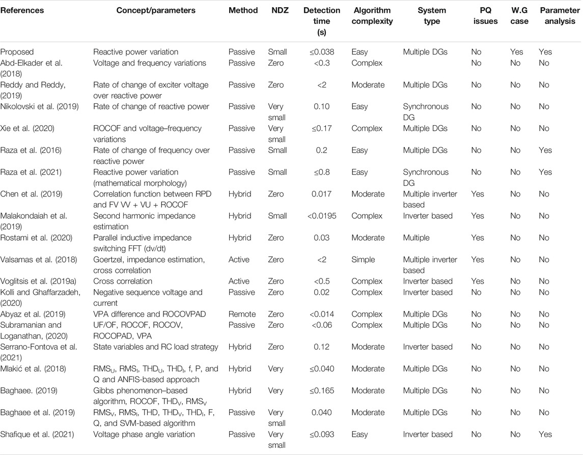
TABLE 6. Comparison of existing islanding detection methods.
Conclusion
In this work, a passive islanding strategy is being developed depending upon the reactive power after the comparative assessment of five different passive indices that are frequency, power factor, voltage, active power, and reactive power. The reactive power Q has the ability to clearly differentiate between the islanding scenarios that include small imbalances between the DG and the load, huge power mismatches, false tripping, or abnormal events that include load injection and ejection, capacitor injection and ejection, motor injection and ejection, various kinds of fault switching, DG tripping, and weak grid contribution. The nominated parameter validates the usefulness of the presented strategy. The performance investigation is further carried out based upon the performance-based factors such as power quality, detection time, execution cost, load quality factors, and non-detection zone. The performance of the anticipated strategy is being authenticated and modeled on the IEEE 1547 standard testing network. The suggested strategy is simple and straightforward, with a very small non-detection zone (NDZ), and has no impact upon power quality, thus making it a better choice for real-time implementation.
Data Availability Statement
The original contributions presented in the study are included in the article/Supplementary Material, and further inquiries can be directed to the corresponding author.
Author Contributions
All authors listed have made a substantial, direct, and intellectual contribution to the work and approved it for publication.
Conflict of Interest
The authors declare that the research was conducted in the absence of any commercial or financial relationships that could be construed as a potential conflict of interest.
Publisher’s Note
All claims expressed in this article are solely those of the authors and do not necessarily represent those of their affiliated organizations, or those of the publisher, the editors, and the reviewers. Any product that may be evaluated in this article, or claim that may be made by its manufacturer, is not guaranteed or endorsed by the publisher.
Supplementary Material
The Supplementary Material for this article can be found online at: https://www.frontiersin.org/articles/10.3389/fenrg.2022.830750/full#supplementary-material
References
Abd-Elkader, A. G., Allam, D. F., and Tageldin, E. (2014). Islanding Detection Method for DFIG Wind Turbines Using Artificial Neural Networks. Int. J. Electr. Power Energ. Syst. 62, 335–343. doi:10.1016/j.ijepes.2014.04.052
Abd-Elkader, A. G., Saleh, S. M., and Magdi Eiteba, M. B. (2018). A Passive Islanding Detection Strategy for Multi-Distributed Generations. Int. J. Electr. Power Energ. Syst. 99, 146–155. doi:10.1016/j.ijepes.2018.01.005
Abyaz, A., Panahi, H., Zamani, R., Haes Alhelou, H., Siano, P., Shafie-khah, M., et al. (2019). An Effective Passive Islanding Detection Algorithm for Distributed Generations. Energies 12 (16), 3160. doi:10.3390/en12163160
Al Hosani, M., Qu, Z., and Zeineldin, H. H. (2015). A Transient Stiffness Measure for Islanding Detection of Multi-DG Systems. IEEE Trans. Power Deliv. 30 (2), 986–995. doi:10.1109/TPWRD.2014.2360876
Aljankawey, A. S., Liu, N., Diduch, C. P., and Chang, L. (2012). A New Passive Islanding Detection Scheme for Distributed Generation Systems Based on Wavelets. IEEE Energ. Convers. Congr. Expo. ECCE 2012, 4378–4382. doi:10.1109/ECCE.2012.6342227
Baghaee, H. R. (2019). Gibbs Phenomenon-Based Hybrid Islanding Detection Strategy for VSC–Based Microgrids Using Frequency Shift. THDU and RMSU.
Baghaee, H. R., Mlakić, D., Nikolovski, S., and Dragicčvić, T. (2019). Anti-islanding protection of PV-Based Microgrids Consisting of PHEVs Using SVMs. IEEE Trans. Smart Grid” 11 (1), 483–500.
Bakhshi, R., and Sadeh, J. (2016). Voltage Positive Feedback Based Active Method for Islanding Detection of Photovoltaic System with String Inverter Using Sliding Mode Controller. Solar Energy 137, 564–577. doi:10.1016/j.solener.2016.08.051
Bakhshi-Jafarabadi, R., and Sadeh, J. (2020). New Voltage Feedback-Based Islanding Detection Method for Grid-Connected Photovoltaic Systems of Microgrid with Zero Non-detection Zone. IET Renew. Power Gener. 14 (10), 1710–1719.
Bakhshi-Jafarabadi, R., Sadeh, J., and Popov, M. (2020). Maximum Power point Tracking Injection Method for Islanding Detection of Grid-Connected Photovoltaic Systems in Microgrid. IEEE Trans. Power Deliv. 36 (1), 168–179.
Bayrak, G. (2015). A Remote Islanding Detection and Control Strategy for Photovoltaic-Based Distributed Generation Systems. Energ. Convers. Manag. 96, 228–241. doi:10.1016/j.enconman.2015.03.004
Bayrak, G., and Kabalci, E. (2016). Implementation of a New Remote Islanding Detection Method for Wind-Solar Hybrid Power Plants. Renew. Sust. Energ. Rev. 58, 1–15. doi:10.1016/j.rser.2015.12.227
Chen, X., Li, Y., and Crossley, P. (2019). A Novel Hybrid Islanding Detection Method for Grid-Connected Microgrids with Multiple Inverter-Based Distributed Generators Based on Adaptive Reactive Power Disturbance and Passive Criteria. IEEE Trans. Power Electron. 34 (9), 9342–9356. doi:10.1109/TPEL.2018.2886930
Faqhruldin, O. N., El-Saadany, E. F., and Zeineldin, H. H. (19922014). A Universal Islanding Detection Technique for Distributed Generation Using Pattern Recognition. IEEE Trans. Smart Grid 5 (4), 1985.
Gupta, P., Bhatia, R. S., and Jain, D. K. (2015). Average Absolute Frequency Deviation Value Based Active Islanding Detection Technique. IEEE Trans. Smart Grid 6 (1), 26–35. doi:10.1109/TSG.2014.2337751
Heidari, M., Seifossadat, G., and Razaz, M. (2013). Application of Decision Tree and Discrete Wavelet Transform for an Optimized Intelligent-Based Islanding Detection Method in Distributed Systems with Distributed Generations. Renew. Sust. Energ. Rev. 27, 525–532. doi:10.1016/j.rser.2013.06.047
Ieee Standard Association (2018). Standard for Interconnection and Interoperability of Distributed Energy Resources with Associated Electric Power Systems Interfaces. IEEE Std. 1547-2018.
Jang, S.-I., and Kim, K.-H. (2004). An Islanding Detection Method for Distributed Generations Using Voltage Unbalance and Total Harmonic Distortion of Current. IEEE Trans. Power Deliv. 19 (2), 745–752. doi:10.1109/tpwrd.2003.822964
Karimi, M., Farshad, M., Hong, Q., Laaksonen, H., and Kauhaniemi, K. (2021). An Islanding Detection Technique for Inverter-Based Distributed Generation in Microgrids. Energies 14 (1), 130.
Karimi, M., Mokhlis, H., Naidu, K., Uddin, S., and Bakar, A. H. A. (2016). Photovoltaic Penetration Issues and Impacts in Distribution Network - A Review. Renew. Sust. Energ. Rev. 53, 594–605. doi:10.1016/j.rser.2015.08.042
Khamis, A., Shareef, H., Mohamed, A., and Bizkevelci, E. (2015). Islanding Detection in a Distributed Generation Integrated Power System Using Phase Space Technique and Probabilistic Neural Network. Neurocomputing 148, 587–599. doi:10.1016/j.neucom.2014.07.004
Kim, M.-S., Haider, R., Cho, G.-J., Kim, C.-H., Won, C.-Y., and Chai, J.-S. (2019). Comprehensive Review of Islanding Detection Methods for Distributed Generation Systems. Energies 12 (5), 837. doi:10.3390/en12050837
Kolli, A. T., and Ghaffarzadeh, N. (2020).A Novel Phaselet-Based Approach for Islanding Detection in Inverter-Based Dis-Tributed Generation Systems. Electr. Power Syst. Res. 182. doi:10.1016/j.epsr.2020.106226
Malakondaiah, M., Boddeti, K. K., Ramesh Naidu, B., and Bajpai, P. (2019). Second Harmonic Impedance Drift‐based Islanding Detection Method. IET Generation, Transm. Distribution 13 (23), 5313–5324. doi:10.1049/iet-gtd.2018.6838
Manditereza, P. T., and Bansal, R. (2016). Renewable Distributed Generation: The Hidden Challenges - A Review from the protection Perspective. Renew. Sust. Energ. Rev. 58, 1457–1465. doi:10.1016/j.rser.2015.12.276
Manikonda, S. K. G., and Gaonkar, D. N. (2019). Comprehensive Review of IDMs in DG Systems. IET Smart Grid 2 (1), 11–24. doi:10.1049/iet-stg.2018.0096
Mishra, M., Chandak, S., and Rout, P. K. (2019). Taxonomy of Islanding Detection Techniques for Distributed Generation in Microgrid. Renew. Energ. Focus 31 (00), 9–30. doi:10.1016/j.ref.2019.09.001
Mishra, P. P., Bhende, C. N., and Manikandan, M. S. (2020). Islanding Detection Using Total Variation‐based Signal Decomposition Technique. IET Energ. Syst. Integration 2 (1), 22–31. doi:10.1049/iet-esi.2019.0079
Mlakić, D., Baghaee, H. R., and Nikolovski, S. (2018). A Novel ANFIS-Based Islanding Detection for Inverter-Interfaced Microgrids. IEEE Trans. Smart Grid 10 (4), 4411–4424.
Mohamad, H., Mokhlis, H., Bakar, A. H. A., and Ping, H. W. (2011). A Review on Islanding Operation and Control for Distribution Network Connected with Small Hydro Power Plant. Renew. Sust. Energ. Rev. 15 (8), 3952–3962. doi:10.1016/j.rser.2011.06.010
Nale, R., Biswal, M., and Kishor, N. (2019). A Transient Component Based Approach for Islanding Detection in Distributed Generation. IEEE Trans. Sustain. Energ. 10 (3), 1129–1138. doi:10.1109/TSTE.2018.2861883
Nikolovski, S., Baghaee, H. R., and Mlakic, D. (2019). Islanding Detection of Synchronous Generator-Based DGs Using Rate of Change of Reactive Power. IEEE Syst. J. 13 (4), 4344–4354. doi:10.1109/JSYST.2018.2889981
Papadimitriou, C. N., Kleftakis, V. A., and Hatziargyriou, N. D. (2015). A Novel Islanding Detection Method for Microgrids Based on Variable Impedance Insertion. Electric Power Syst. Res. 121, 58–66. doi:10.1016/j.epsr.2014.12.004
Pinto, S. J., and Panda, G. (2015). Wavelet Technique Based Islanding Detection and Improved Repetitive Current Control for Reliable Operation of Grid-Connected PV Systems. Int. J. Electr. Power Energ. Syst. 67, 39–51. doi:10.1016/j.ijepes.2014.11.008
Raza, S., Mokhlis, H., Arof, H., Laghari, J. A., and Mohamad, H. (2016). A Sensitivity Analysis of Different Power System Parameters on Islanding Detection. IEEE Trans. Sustain. Energ. 7 (2), 461–470. doi:10.1109/TSTE.2015.2499781
Raza, S., ur Rahman, T., Saeed, M., and Jameel, S. (2021). Performance Analysis of Power System Parameters for Islanding Detection Using Mathematical Morphology. Ain Shams Eng. J. 12, 517–527. doi:10.1016/j.asej.2020.07.023
Reddy, C. R., and Reddy, K. H. (2019). A New Passive Islanding Detection Technique for Integrated Distributed Generation System Using Rate of Change of Regulator Voltage over Reactive Power at Balanced Islanding. J. Electr. Eng. Technol. 14 (2), 527–534. doi:10.1007/s42835-018-00073-x
Rostami, A., Jalilian, A., Zabihi, S., Olamaei, J., and Pouresmaeil, E. (2020). Islanding Detection of Distributed Generation Based on Parallel Inductive Impedance Switching. IEEE Syst. J. 14 (1), 813–823. doi:10.1109/JSYST.2019.2923289
Serrano-Fontova, A., Martinez, J. A., Casals-Torrens, P., and Bosch, R. (2021). A Robust Islanding Detection Method with Zero-Non-Detection Zone for Distribution Systems with DG. Int. J. Electr. Power Energ. Syst. 133, 107247. doi:10.1016/j.ijepes.2021.107247
Shafique, N., Raza, S., Munir, H. M., Bukhari, S. S. H., and Ro, J.-S. (2021). Islanding Detection Strategy for Wind Farm Based on Performance Analysis of Passive Indices Having Negligible NDZ. Appl. Sci. 11 (21), 9989. doi:10.3390/app11219989
Shyh-Jier Huang, F.-S., and Huang, S.-J. (2001). A Detection Algorithm for Islanding-Prevention of Dispersed Consumer-Owned Storage and Generating Units. IEEE Trans. Energ. Convers. 16 (4), 346–351. doi:10.1109/60.969474
Sivadas, D., and Vasudevan, K. (2019). An Active Islanding Detection Strategy with Zero Nondetection Zone for Operation in Single and Multiple Inverter Mode Using GPS Synchronized Pattern. IEEE Trans. Ind. Electron. 67 (7), 5554–5564.
Subramanian, K., and Loganathan, A. K. (2020). Islanding Detection Using a Micro-synchrophasor for Distribution Systems with Distributed Generation. Energies 13 (19), 5180. doi:10.3390/en13195180
Taheri Kolli, A., and Ghaffarzadeh, N. (2020). A Novel Phaselet-Based Approach for Islanding Detection in Inverter-Based Distributed Generation Systems. Electric Power Syst. Res. 182, 106226. doi:10.1016/j.epsr.2020.106226
Valsamas, F., Voglitsis, D., Rigogiannis, N., Papanikolaou, N., and Kyritsis, A. (2018). Comparative Study of Active Anti‐islanding Schemes Compatible with MICs in the prospect of High Penetration Levels and Weak Grid Conditions. IET Generation, Transm. Distribution 12 (20), 4589–4596. doi:10.1049/iet-gtd.2018.5636
Voglitsis, D., Papanikolaou, N. P., and Kyritsis, A. C. (2019). Active Cross-Correlation Anti-islanding Scheme for PV Module-Integrated Converters in the Prospect of High Penetration Levels and Weak Grid Conditions. IEEE Trans. Power Electron. 34 (3), 2258–2274. doi:10.1109/TPEL.2018.2836663
Voglitsis, D., Valsamas, F., Rigogiannis, N., and Papanikolaou, N. (2018). On the Injection of Sub/inter-Harmonic Current Components for Active Anti-islanding Purposes. Energies 11 (9), 2183. doi:10.3390/en11092183
Voglitsis, D., Valsamas, F., Rigogiannis, N., and Papanikolaou, N. P. (2019). On Harmonic Injection Anti-islanding Techniques under the Operation of Multiple Der-Inverters. IEEE Trans. Energ. Convers. 34 (1), 455–467. doi:10.1109/TEC.2018.2881737
Xie, X., Huang, C., and Li, D. (2020). A New Passive Islanding Detection Approach Considering the Dynamic Behavior of Load in Microgrid. Int. J. Electr. Power Energ. Syst. 117, 105619. doi:10.1016/j.ijepes.2019.105619
Xie, X., Xu, W., Huang, C., and Fan, X. (2021). New Islanding Detection Method with Adaptively Threshold for Microgrid. Electric Power Syst. Res. 195, 107167. doi:10.1016/j.epsr.2021.107167
Zeineldin, H. H., El-Saadany, E. F., and Salama, M. M. A. (2006). Impact of DG Interface Control on Islanding Detection and Nondetection Zones. IEEE Trans. Power Deliv. 21 (3), 1515–1523. doi:10.1109/TPWRD.2005.858773
Glossary
AC Alternating current
C.E Capacitor ejection
C.I Capacitor injection
D.T DG tripping
DC Direct current
DERs Distributed energy resources
DFIG Doubly fed induction generator
DG Distributed generation
F.S Fault switching
GPS Global positioning system
IDM Islanding detection method
IEEE The Institute of Electrical and Electronics Engineers
IGBT Insulated-gate bipolar transistor
L.E Load ejection
L.I Load injection
M.E Motor ejection
M.I Motor injection
MM Mathematical morphology
NDZ Non-detection zone
PCC Point of common coupling
PLCC Power line carrier communication
ROCOFOQ Rate of change of frequency over reactive power
ROCOV Rate of change of voltage
SCADA Supervisory control and data acquisition
STD Standard
THD Total harmonic distortion
VNF Voltage negative feedback
W.G Weak grid
Variable/Parameter/Units
(Q) Reactive power
µF Microfarad
AB Two-phase fault
ABC Three-phase fault
ABCG Three phase to ground fault
ABG Two phase to ground fault
AG One phase to ground fault
C Capacitance of load (Farad)
C.BDG Circuit breaker of the DG side
C.BGrid Circuit breaker of the grid side
cos φ Power factor
f Frequency
fn Nominal frequency
hp Horsepower
Hz Hertz (frequency unit)
Hz/s Hertz per second
I Current
KV Kilovolt
L Inductance of load (Henry)
MVA Mega-volt ampere
MW Megawatt
OF/UF Over-frequency/under-frequency
OV/UV Over-voltage/under-voltage
PDG Active power of DG (MW)
PGRID Active power of grid (MW)
PLOAD Active power of load (MW)
Pmax Maximum amount of active power delivered by the grid (MW)
Pmin Minimum amount of active power delivered by the grid (MW)
pu Per unit
QC Capacitive reactance of load
QDG Reactive power of DG (MVars)
Qf Load quality factors
QGRID Reactive power of grid (MVars)
QL Inductive reactance of load
QLOAD Reactive power of load (MVars)
Qmax Maximum amount of reactive power delivered by the grid (MVars)
Qmeasured Measured value of active power (MW)
Qmin Minimum amount of reactive power delivered by the grid (MVars)
Qref Q reference (reactive power reference input)
Qthreshold Measured value of reactive power (MVars)
R Load/fault resistance
Rg Fault ground resistance
s Seconds
V Rated voltage
Δf Frequency deviation
ΔV Change in voltage level
π 3.14 (pie value)
Ω Ohm
ωn 2 x π x f (angular frequency).
Keywords: islanding, non-detection zone (NDZ), distributed energy resources, passive indices, weak grid
Citation: Raza S, Munir HM, Shafique N, Amjad W, Bajaj M and Alghaythi ML (2022) Implementation of Islanding Recognizing Technique for Wind Distributed Generations Considering Insignificant NDZ. Front. Energy Res. 10:830750. doi: 10.3389/fenrg.2022.830750
Received: 07 December 2021; Accepted: 10 January 2022;
Published: 28 January 2022.
Edited by:
G. M. Shafiullah, Murdoch University, AustraliaReviewed by:
Srete Nikolovski, Josip Juraj Strossmayer University of Osijek, CroatiaAsma Aziz, Edith Cowan University, Australia
Tareq Aziz, Ahsanullah University of Science and Technology, Bangladesh
Copyright © 2022 Raza, Munir, Shafique, Amjad, Bajaj and Alghaythi. This is an open-access article distributed under the terms of the Creative Commons Attribution License (CC BY). The use, distribution or reproduction in other forums is permitted, provided the original author(s) and the copyright owner(s) are credited and that the original publication in this journal is cited, in accordance with accepted academic practice. No use, distribution or reproduction is permitted which does not comply with these terms.
*Correspondence: Hafiz Mudassir Munir, bXVkYXNzaXIubXVuaXJAaWJhLXN1ay5lZHUucGs=; Mamdouh L. Alghaythi, bWxhbGdoYXl0aGlAanUuZWR1LnNh