- 1Electric Power Research Institute, China Southern Power Grid, Guangzhou, China
- 2School of Electrical and Electronic Engineering, Shandong University of Technology, Zibo, China
As natural lightning strikes on a transmission tower, lightning current will flow along grounding lines into the adjacent tower grounding grid. As lightning current is dispersed from the tower grounding grid into the soil, a lightning overvoltage may be produced on adjacent pipelines. In this paper, the lightning current shunt characteristics in multi-tower scenarios are calculated by simulation method under different soil resistivity conditions. Then, based on the lightning current shunt characteristics, the current dispersion process among multi-tower grounding grids and the pipeline is analyzed with different soil resistivities, gap distances, and lightning current amplitudes. Finally, the protective effect of “drain wire” and “forced commutation” on pipeline overvoltage are compared. Simulation results showed that with increasing soil resistivity, tower grounding resistance was increased and tower shunt coefficient decreased. Considering lightning current through the multi-tower grounding grids, pipeline overvoltage is much larger than that of a single tower. Pipeline overvoltage is increased with soil resistivity and lightning current amplitude, while it is decreased with “pipeline-line” distance. Both “drain wire” method and “forced commutation” method can effectively reduce pipeline potential.
Introduction
In recent years, accidents involving the explosion of oil and gas pipelines have happened occasionally in locations such as Kazakhstan, Shiyan in Hubei, and Huangdao in Qingdao. Restricted by land resources and pipeline transportation routes, transmission lines and pipelines are often crossed and parallel (Xun et al., 2017; Xun et al., 2020a; Rui et al., 2020; Yang et al., 2021a; Shen et al., 2021). When lightning strikes the transmission tower, most of the lightning current will flow into the ground through the grounding grid of the tower; but some lightning current also flows along grounding lines into adjacent towers. Lightning current dispersion through the tower grounding grid can create generation-induced overvoltage on the adjacent pipelines that may affect the safety of the pipeline (Hu et al., 2021; Yan et al., 2021). It is therefore of great significance to research the induced lightning overvoltage of pipelines from adjacent transmission lines (Xun et al., 2020b; Yang et al., 2021b).
Many people have done a lot of research work on the overvoltage and protection of the pipeline near the lines. In one study (WAN et al., 2009), the influence of “pipeline-line” distance, “pipeline-line” crossing angle, and soil resistivity on pipeline overvoltage were analyzed in detail. Another (TAN et al., 2019) analyzed the effect of reducing the pipeline overvoltage by arrangement drain wire, and other research (WANG, 2017) has analyzed the pipeline overvoltage under three working conditions of the normal operation of the line, grounding fault, and lightning strike fault. Some studies have (Hongfeng et al., 2012; Ning et al., 2012; CHEN et al., 2017; Zhiqiang et al., 2019; Hongjie et al., 2021) used electromagnetic transient software ATP-EMTP to analyze the interference voltage of pipelines on lightning strike towers or researched the interference of pipelines on the direct current grounding electrode (Longhai, 2019; CHENG et al., 2021). This previous research largely considered the pipeline overvoltage caused by lightning current dispersion from lightning striking transmission towers nearby. However, few studies have considered the influence of multi-tower current shunts. Therefore, we conducted a series of studies on the pipeline lightning overvoltage, considering the current shunt effect of adjacent multi-tower grounding grids. The lightning current distribution feature of multi-tower grounding grids was calculated and analyzed under different soil resistivity conditions. Based on these calculation results, a lightning current dispersion model of a multi-tower grounding grid and oil and gas pipeline was built to analyze the effect of different soil resistivity, “pipeline-line” distance, and lightning current amplitude on pipeline overvoltage. Finally, a comparison study will be carried out between the protective effect of “drain wire” and “forced commutation” on pipeline overvoltage.
Simulation Model and Parameters of Transmission Line and Pipeline
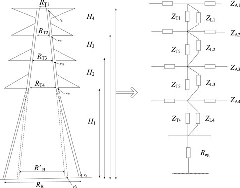
To reduce the influence of the high-frequency component of lightning current on transmission line parameters, a frequency dependent Jmarti line model is applied (Salarieh et al., 2020). Considering the lightning current propagation process in a tower, the equivalent distribution multi-wave impedance tower model is used. The model equates the tower to the model shown in Figure 1; the calculation formula of the wave impedance of each part is as follows (Ishii et al., 1991).
The lightning current will be damped to 0 after a traveling distance of five transmission spans (Visacro et al., 2004). Therefore, six spans are considered on both sides of a lightning struck tower. As shown in Figure 2A, T0 represent the lightning strike tower, TRx and TLx represent the right and left towers of the lightning strike towers respectively.

FIGURE 2. Simulation diagram of tower grounding grid and pipeline. (A) shows the diagram of lightning striking case between transmission lines and oil and gas pipeline. (B) shows the relative position of the tower grounding grid and the oil and gas pipeline.
The tower grounding grid and adjacent pipeline model is calculated by the finite element method. The grounding resistance of the grounding grid is calculated under different soil resistivities.
The grounding grid material is galvanized round steel with a diameter Φ = 16 mm. The buried depth is 0.8 m. The grounding grid is a square with a side length of 15 m and the extended grounding electrode length of 20 m. The angle between them is 135°. The down-lead length of the grounding grid is 0.8 m. The length of the oil and gas pipeline is 400 m with two ends grounded.
Transmission lines, tower grounding grids, and pipeline models are shown in Figure 2B. The “pipeline-line” distance D1 and D2 represent the distance between the T0 and TR1 towers grounding grid and pipeline respectively. Here, the value of D1+ D2 is constant as 300 m.
Calculation of Lightning Current Shunt Among Multi-Tower Grounding Grids
Lightning Current Distribution
The applied waveform of the lightning current is 2.6/50 μs with an amplitude of 100 kA. The soil resistivity is 500 Ω m for lightning current is symmetrically distributed on the right and left sides of the lightning striking tower, lightning current distribution in towers is shown in Figure 3A. The lightning current through the T0 tower is the largest of about 96 kA; the lightning current through TR1 and TL1 tower is about 24 kA. Because of the lightning current of the tower grounding grid and “pipeline-line” distance, the lightning current through the TL1 TR2, TL2, TR3, TL3, TR4, TL4, TR5, TL5, TR6, and TL6 towers are too small to affect the adjacent pipelines.
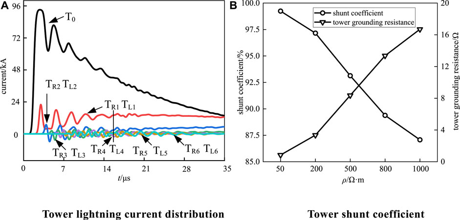
FIGURE 3. Tower lightning current distribution. (A) Tower lightning current distribution (B) Tower shunt coefficient.
Lightning Current Shunt Coefficient
The lightning current shunt coefficient β of the tower reflects the lightning current entering the ground through the tower (WU and Xianglin, 2012; WU and WANG, 2014; Tang et al., 2015; Bai et al., 2016). The tower shunt coefficient β is defined as the ratio of the tower grounding current It to the total lightning current Iz.
The grounding line shunt coefficient α is defined as the ratio of the current Ib1 + Ib2 to the total lightning current Iz. The Ib1 and Ib2 represent lightning current flowing through grounding lines on both sides of the tower.
Grounding resistance directly affects the tower shunt coefficient. The soil resistivity is 50 Ω m, 200 Ω m, 500 Ω m, 800 Ω m, 1000 Ω m. The tower shunt coefficient is shown in Figure 3B. As the soil resistivity increases from 50 Ω m to 1000 Ω m, the tower grounding resistance increases from 0.84 to 16.7Ω. The tower shunt coefficient decreased from 99.2 to 87.1%. The reason is that with the decrease of soil resistivity, the lightning current is more likely to disperse in the soil, increasing the tower shunt coefficient.
Pipeline Overvoltage Under Multi-Towers Lightning Current Dispersion
According to the lightning current distribution calculated in Section Calculation of Lightning Current Shunt Among Multi-Tower Grounding Grids, most of the lightning current flows through T0 and TR1 as lightning strikes tower T0 as shown in Figure 1. Hence, based on the lightning current distribution calculation results in Section Calculation of Lightning Current Shunt Among Multi-Tower Grounding Grids, the lightning current of the T0 tower grounding grid is obtained by the T0 tower shunt coefficient β. The lightning current of the TR1 tower grounding grid is obtained by fitting.
Effect of Soil Resistivity
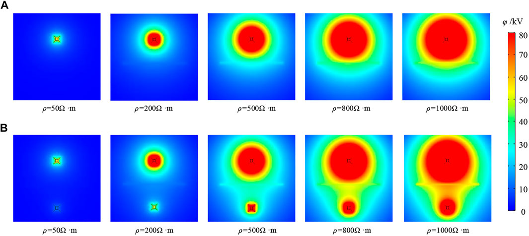
To study the effect of soil resistivity on grounding characteristics of grounding devices (Heimbach and Grcev, 1997; Grcev, 2009; Visacro, 2018; Salarieh et al., 2019), the soil resistivity is taken as 50 Ω m, 200 Ω m, 500 Ω m, 800 Ω m, 1000 Ω m. The applied lightning current amplitude I0 = 100 kA. The “pipeline-line” distance D1 = D2 = 150 m. Two individual cases are considered as only grounding grid of T0 tower and two grounding grids of T0 and TR1 tower. The potential distribution of grounding grids, pipelines, and surrounding soil are shown in Figure 4.
As the soil resistivity increases, the effective current dispersion region of the tower grounding grid gradually increases in both cases. The reason for this is that the increasing soil resistivity prevents the tower grounding grid current from flowing into the surrounding soil resulting in that most of the current diffuses the far end through the extended electrode.
It can be seen from Figure 4 that in one case, only considering the grounding grid of the T0 tower, as the soil resistivity increases from 50 Ω m to 1000 Ω m, the pipeline potential increases from 2.71 to 47.50 kV, while the pipeline insulation layer withstands voltage increase from 0.72 to 2.39 kV. In the other case, considering both grounding grids of T0 and TR1 tower, as soil resistivity increases from 50 Ω m to 1000 Ω m, the pipeline potential increases from 3.22 to 57.41 kV. The pipeline insulation layer withstands a voltage increase from 0.80 to 2.67 kV. The pipeline potential and the voltage of the pipeline insulation layer is larger in the second case.
Effect of “Pipeline-Line” Distance D1
To study the effect of “pipeline-line” distance D1 on the pipeline overvoltage, distance D1 is taken as 110, 130, 150, 170, and 190 m with D1+D2 = 300 m. The soil resistivity is 500 Ω m and the lightning current amplitude is I0 = 100 kA. Pipeline potential and insulating layer voltage are as shown in Figure 5. In both cases, the pipeline potential and the withstand voltage of the pipeline insulation layer decreases with distance D1.
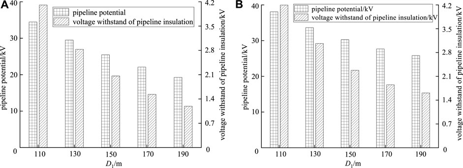
FIGURE 5. Influence of D1 on pipeline potential and insulating layer voltage. (A) shows the overvoltage of the grounding grid of the T0 tower to the adjacent pipeline. (B) shows the overvoltage of the adjacent pipeline due to the common dispersion of the T0 and TR1 tower grounding grids.
Effect of Lightning Current Amplitude I0
To study the effect of lightning current amplitude I0 on the pipeline overvoltage, the lightning current amplitude I0 is taken as 40, 55, 70, 85, and 100 kA. The soil resistivity is 500 Ω m and the “pipeline-line” distance D1 = D2 = 150 m. Pipeline potential and insulating layer voltage are calculated. When only considering grounding current dispersion of T0 tower, the pipeline potential and the withstand voltage of the pipeline insulation layer increases with the lightning current amplitude I0. When the lightning current amplitude I0 increases from 40 to 100 kA, the pipeline potential increases from 10.18 to 25.45 kV, and the pipeline insulation layer withstand voltage increases from 0.83 to 2.06 kV. When considering grounding current dispersion of both the T0 and TR1 tower, the pipeline potential and the withstand voltage of the pipeline insulation layer increases with the lightning current amplitude I0. When the lightning current amplitude I0 = 100 kA, the pipeline potential and the voltage of the pipeline insulation layer are the largest as 30.28 and 2.28 kV respectively. Compared with only considering the grounding current dispersion of T0 tower, pipeline potential and pipeline insulation withstand voltage increases by 4.83 and 0.22 kV respectively.
Pipeline Overvoltage Protection Measures
Currently, most of the lines near the pipeline overvoltage protection methods are as shown in Figure 6A, where D3 is the distance between the copper wire and oil and gas pipeline, D4 is the length of copper wire. In this paper, a novel grounding current dispersion method of the “forced commutation” method is proposed for pipeline overvoltage protection, as shown in Figure 6B. This method is to connect the epitaxial rays of the grounding grid near the pipeline side to the other side. The epitaxial rays of grounding grids away from the pipeline side increased from 20 to 40 m.
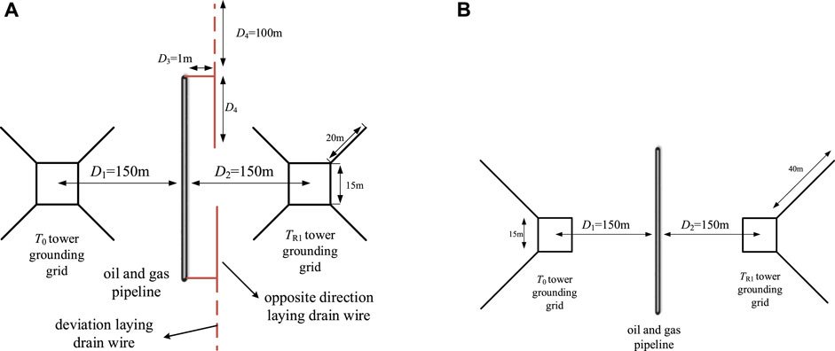
FIGURE 6. Pipeline overvoltage protection methods. (A) shows the schematic diagram of drain wire in pipeline overvoltage protection measures. (B) shows the schematic diagram of forced commutation in pipeline overvoltage protection measures.
To study the effect of drain wire and forced commutation on pipeline overvoltage, a simulation was conducted. During the simulation, the soil resistivity was 500 Ω m, and the lightning current amplitude I0 was 70, 85, and 100 kA. The “pipeline-line” distance D1 = D2. The simulation results are shown in Table 1.
It can be seen from Table 1 that laying drain wire and adopting forced commutation can reduce pipeline potential. When the lightning current amplitude I0 is 70, 85, and 100 kA. The deviation laying drain wire makes the pipeline potential decrease 3.76, 4.59, and 5.45 kV respectively. The forced commutation makes the pipeline potential decrease 2.05, 2.53, and 2.92 kV respectively, even though the effect of lowering pipeline potential is weaker than deviation laying drain wire. If 200 m of copper is too expensive, and need to dig 200 m of channel, construction complex and difficult. In contrast, “forced commutation” requires lower engineering costs, and the construction is simple.
Conclusion
This paper focuses on the overvoltage problem affecting transmission lines near a pipeline, and examined the influence of the lightning current dispersion of multi-towers on adjacent pipeline overvoltage. In this paper, a novel grounding current dispersion method of “forced commutation” is proposed Based on the above research, the conclusions are as follows:
1) The tower grounding resistance and tower shunt coefficient were greatly affected by soil resistivity.
2) Considering lightning current through the multi-tower grounding grids, pipeline overvoltage is much larger than that of a one with a single tower. When the soil resistivity is 1000 Ω m, lightning current amplitude is 100 kA, and “pipeline-line” distance D1 = D2. Compared with single tower grounding dispersion, the pipeline potential increased by 10 kV.
3) Although deviation laying drain wire has the best protection effect on pipeline overvoltage, the forced commutation method is more economical and convenient.
Data Availability Statement
The original contributions presented in the study are included in the article/Supplementary Material, further inquiries can be directed to the corresponding authors.
Author Contributions
SH: conceptualization, writing-original draft preparation, simulation; YH: CDEGS software simulation: ATP-EMTP software and grounding test; JW: Assist with software simulation; YA: software; GL: project administration and data arrangement; ZL: supervision; YC: supervision and proofreading.
Funding
This manuscript was supported by the China Southern Power Grid Science and Technology Project (CSGULAEMEST-2021-KF-05), Natural Science Foundation of China (under Grant 51807113), and the Shandong Provincial Natural Science Foundation, China (ZR2021ME092).
Conflict of Interest
SH and GL were employed by the company Electric Power Research Institute, China Southern Power Grid.
The remaining authors declare that the research was conducted in the absence of any commercial or financial relationships that could be construed as a potential conflict of interest.
Publisher’s Note
All claims expressed in this article are solely those of the authors and do not necessarily represent those of their affiliated organizations, or those of the publisher, the editors and the reviewers. Any product that may be evaluated in this article, or claim that may be made by its manufacturer, is not guaranteed or endorsed by the publisher.
References
Chen, D., Linfeng, X. I. E., and Amp, G. V. (2017). Disturbance and Influence of Transmission Line Struck by Lightning on Above-Ground Oil and Gas Pipeline[J]. Insulators and Surge Arresters (02), 85–89. doi:10.16188/j.isa.1003-8337.2017.02.017
Bai, F., Lu, J., Lin, S., and Yang, Z. (2016). Analysis of Electromagnetic Effect of UHV AC and DC Transmission Lines in Same Corridor Innormal Operation on Adjacent Petroleum & Gas Pipelines[J]. Poer Syst. Tech. 40 (11), 3609–3614. doi:10.13335/j.1000-3673.pst.2016.11.049
Cheng, Hongbo., Feng, Xiahui., and Wang, Xun. (2021). Protective Performance of Mitigation Wires Mounted along Metal Pipelines Around DC Grounding Electrode[J]. Insulators and Surge Arresters (01), 83–89. doi:10.16188/j.isa.1003-8337.2021.01.013
Grcev, L. (2009). Time- and Frequency-dependent Lightning Surge Characteristics of Grounding Electrodes. IEEE Trans. Power Deliv. 24 (4), 2186–2196. doi:10.1109/tpwrd.2009.2027511
Heimbach, M., and Grcev, L. D. (1997). Grounding System Analysis in Transients Programs Applying Electromagnetic Field Approach. IEEE Trans. Power Deliv. 12 (1), 186–193. doi:10.1109/61.568240
Hongfeng, X. I. A. O., Luo, Richeng., and Huang, Jun., (2012). Electromagnetic Effect on Parallel Oil/Gas Pipelines when Lightning Strike on AC/DC Transmission Lines on the Same Tower[J]. Insulators and Surge Arresters (03), 15–21. doi:10.16188/j.isa.1003-8337.2021.03.003
Hongjie, G. U., Huang, Yanyan., and Zhang, Jiahao. (2021). Electromagnetic Influence of 500/± 800 kV AC/DC Mixed Voltage Transmission Lines on Parallel Oil and Gas Pipelines[J]. Insulators and Surge Arresters (03), 22–28. doi:10.16188/j.isa.1003-8337.2021.03.004
Hu, Y., Lin, Y., An, Y., Wen, X., Li, H., Su, M., et al. (2021). Laboratory Study on Negative Spark Inception Direction and Breakdown Characteristics in Rod-Rod Air Gaps. Electric Power Syst. Res. 201, 107498. doi:10.1016/j.epsr.2021.107498
Ishii, M., Kawamura, T., Kouno, T., Ohsaki, E., Shiokawa, K., Murotani, K., et al. (1991). Multi-story Transmission Tower Model for Lightning Surge Analysis[J]. IEEE Trans. Power Deliv. 63, 1335–1372. doi:10.1109/61.85882
Longhai, F. U. (2019). Analysis and Mitigation on Electromagnetic Interference on Pipelines Due to High-Voltage Direct Current Ground Electrode[J]. Xi’an, China: Insulators and Surge Arresters.
Ning, A. N., Yi, P. E. N. G., and Xiancang, A. I. (2012). Electromagnetic Effects on Underground Oil/Gas Pipeline of the Lightning Strike on EHV AC Transmission Line[J]. High Voltage Eng. 38 (11), 2881–2888. doi:10.3969/j.issn.1003-6520.2012.11.015
Rui, L. I., Quan, Q., and Wang, Yong. (2020). Study on the Safety Impact of Transmission Line on Oil and Gas Pipeline Operation Based on CDEGS[J]. Insulators and Surge Arresters (05), 171–175. doi:10.16188/j.isa.1003-8337.2020.05.028
Salarieh, B., Silva, H., and Gole, A. M. (2020). An Electromagnetic Model for the Calculation of Tower Surge Impedance Based on Thin Wire Approximation. Piscataway, NJ, United States: IEEE Transactions on Power Delivery.
Salarieh, B., Silva, H., and Kordi, B. (2019). “Wideband EMT-Compatible Model for Grounding Electrodes Buried in Frequency Dependent Soil[C]//IPST2019 - International Conference on Power Systems Transients,” in International Conference on Power Systems Transients.
Shen, X., Ouyang, T., Khajorntraidet, C., Li, Y., Li, S., and Zhuang, J. (2021). Mixture Density Networks-Based Knock Simulator. IEEE/ASME Trans. Mechatronics, 1, 1. doi:10.1109/tmech.2021.3059775
Tan, B., Xuefang, T., and Zhang, K. (2019). Study on Protective Measures and Protective Effects of Buried Oil and Gas Pipelines when Lightning Strikes on Line Towers[J]. Insulators and Surge Arresters (02), 9–13. doi:10.16188/j.isa.1003-8337.2019.02.002
Tang, L., Li, H., Gao, J., Hao, Y., and Li, L. (2015). Study on the Modeling Approach of Lightning Current and its Influence on Overhead Line Lightning Withstand Performance Analysis[J]. Insulators and Surge Arresters (02), 37–43. doi:10.16188/j.isa.1003-8337.2015.02.008
Visacro, Silvério., Soares, A., Marco, A., and Schroeder, O., (2004). Statistical Analysis of Lightning Current Parameters: Measurements at Morro Do Cachimbo Station[J]. J. Geophys. Res. Atmospheres 109 (1). doi:10.1029/2003jd003662
Visacro, Silverio. (2018). The Use of the Impulse Impedance as a Concise Representation of Grounding Electrodes in Lightning Protection Applications[J]. IEEE Trans. Electromagn. Compatibility, 1–4. doi:10.1109/TEMC.2017.2788565
Wan, Baoquan., Huichun, X. I. E., and Zhang, Xiaowu. (2009). Influence of Lightning Strike to UHV AC Double-Circuit Tower on Oil or Gas Pipelines[J]. High Voltage Eng. 35 (08), 1812–1817. doi:10.1016/j.apm.2007.10.019
Wang, Pei. (2017). Research on Electormagnetic Influence and Protective Measures of High Voltage AC Transmission Lines on Crossing Gas/Oil Pipelines[D]. Beijing, China: North China Electric Power University.
Wu, Wenhui., and Xianglin, C. A. O. (2012). Power System Electromagnetic Transient Calculation and EMTP application[M]. Bei Jing: China Water Conservancy and Hydropower Press.
Wu, Yanbin., and Wang, Yunhao. (2014). Study of Transmission Line Lighting Withstand Level Based on Pilot Method[J]. Insulators and Surge Arresters (01), 115–118. doi:10.16188/j.isa.1003-8337.2014.01.005
Xun, S. H. E. N., Zhang, Xingguo., and Ouyang, Tinghui. (2020). Cooperative Comfortable-Driving at Signalized Intersections for Connected and Automated Vehicles. IEEE Robotics Automation Lett. 5 (4), 6247–6254. doi:10.1109/LRA.2020.3014010
Xun, S. H. E. N., Zhang, Yahui., Kota, S. A. T. A., and Tielong, Shen. (2020). Gaussian Mixture Model Clustering-Based Knock Threshold Learning in Automotive Engines. IEEE/ASME Trans. Mechatronics, 1. doi:10.1109/TMECH.2020.3000732
Xun, S. H. E. N., Zhang, Yahui., Tielong, S. H. E. N., and Khajorntraidet, C. (2017). Spark advance Self-Optimization with Knock Probability Threshold for Lean-Burn Operation Mode of SI Engine. Energy 122 (MAR.1), 1–10. doi:10.1016/j.energy.2017.01.065
Yan, W., An, Y., Hu, Y., Jiang, Z., Gao, X., and Zhou, L. (2021). Research on cylinder Flexible Graphite Earth Electrode (FGEE) Used to Reduce tower Earth Resistance. Electric Power Syst. Res. 196, 107268. doi:10.1016/j.epsr.2021.107268
Yang, N., Yang, C., and Wu, L. (2021). Intelligent Data-Driven Decision-Making Method for Dynamic Multi-Sequence: An E-Seq2Seq Based SCUC Expert System. IEEE Trans. Ind. Inform. 18 (5), 3126–3137. doi:10.1109/tii.2021.3107406
Yang, N., Yang, C., Xing, C., Ye, D., Jia, J., Chen, D., et al. (2021). Deep Learning-Based SCUC Decision-Making: An Intelligent Data-Driven Approach with Self-Learning Capabilities. IET Generation, Transmation&Distribution 16 (4), 629–640. doi:10.1049/gtd2.12315
Keywords: transmission line, oil and gas pipeline, the multi-tower grounding grid, pipeline overvoltage, lightning strike
Citation: Hu S, Hu Y, Wang J, An Y, Liu G, Liu Z and Cheng Y (2022) Research on Lightning Overvoltage of Oil-Gas Pipeline Caused by Lightning Strikes on Adjacent Electrical Transmission Line. Front. Energy Res. 10:830638. doi: 10.3389/fenrg.2022.830638
Received: 08 December 2021; Accepted: 19 January 2022;
Published: 18 March 2022.
Edited by:
Bin Zhou, Hunan University, ChinaCopyright © 2022 Hu, Hu, Wang, An, Liu, Liu and Cheng. This is an open-access article distributed under the terms of the Creative Commons Attribution License (CC BY). The use, distribution or reproduction in other forums is permitted, provided the original author(s) and the copyright owner(s) are credited and that the original publication in this journal is cited, in accordance with accepted academic practice. No use, distribution or reproduction is permitted which does not comply with these terms.
*Correspondence: Yuanchao Hu, aHV5dWFuY2hhbzMyMTFAMTI2LmNvbQ==; Yunzhu An, YW55dW56aHUyMDA2QDE2My5jb20=
 Shangmao Hu1
 Yuanchao Hu
 Jing Wang
 Yunzhu An
 Zhixiang Liu
 Yan Cheng