 Yuanchao Hu1Zhixiang Liu1Tao Huang2Yunzhu An1*Wentao Shen2Shangmao Hu3Chenghui Ma4Bingchen An4Dan Chen4
- 1School of Electrical and Electronic Engineering, Shandong University of Technology, Zibo, China
- 2Construction Branch of State Grid Jiangsu Electric Power Co., Ltd., Nanjing, China
- 3Electric Power Research Institute, China Southern Power Grid, Guangzhou, China
- 4Jining Huayuan Thermal Power Plant, Jining, China
Restricted by cultivated land vegetation, road construction, and land acquisition compensation costs, the grounding electrode extension method is not applicable for grounding resistance reduction of some wind turbines in limited areas. A new grounding resistance reduction method is proposed and verified for wind turbines by connecting nearby wind turbine grounding grids. To study the efficiency of the proposed method, the grounding characteristics of connected grounding grids are calculated. Simulation results indicate that the grounding resistance of connected grounding grids is smaller than that of box extension grounding grids. The grounding characteristics of the grounding grid connection are affected by grounding current frequency and material parameters. The grounding grid connection increases the current dispersion area and reduces the ground potential rise of the grounding conductor.
Introduction
Lightning discharge is an important factor affecting the stability of power systems. The lightning back flashover is the main reason for lightning accidents in wind turbines (Zhang et al., 2015; Kuklin, 2016; Shen et al., 2020). Reducing the grounding resistance is an effective measure to improve the lightning withstanding level of wind turbines and power systems (Wu et al., 2014; Shen et al., 2017; Taha et al., 2020). However, the grounding construction of a wind turbine is restricted by cultivated land vegetation, road construction, and land acquisition compensation costs in practical grounding engineering, which affect the current dissipation and resistance reduction of the grounding grid.
In recent years, a lot of research studies were conducted on the grounding resistance reduction of grounding grids. Li et al. (2013) conducted a comparison simulation test on the horizontal star grounding grid with and without spicules. The results show that the local structure change of the grounding grid can expand the spark discharge area and reduce the impulse grounding impedance. Yuan et al., 2012; Zhu et al., 2015 conducted a systematic study to analyze the effect of the spicule’s length, the spicule’s location, and the distance between adjacent spicules on the grounding characteristics of the grounding grid. Caetano et al. (2018) proposed the arrangement method of connecting the tower foundation to a set of additional grounding grids by using overhead lines to increase the dispersion length and reduce the grounding impedance. Alipio et al., 2021 show that when the wind turbine grounding systems are connected by a bare conductor, the ground potential rise (GPR) peak reduction is due to the connecting electrode, and when the connection is made through an insulated electrode, the GPR reduction is related to the current that is partly diverted to the adjacent grounding grid, especially for high-resistivity soils. Gao et al., 2018 conducted a series of calculations based on a typical tower grounding grid model to study the influence of length and number of vertical grounding electrodes on grounding resistance reduction. In recent years, non-metallic grounding material has been applied to the tower grounding grid (Hu et al., 2016; Shen and Pongsathorn, 2021; Sun et al., 2021) Compared with galvanized steel, the flexible graphite composite grounding material can effectively reduce the grounding resistance under a high-frequency current.
Currently, there are few studies on the current dispersion and resistance reduction of the wind turbine grounding grid under a limited construction area. A new grounding resistance reduction method is proposed in this article for wind turbines by connecting nearby wind turbine grounding grids together. Two grounding resistance reduction methods are compared in detail, including grounding grids with the traditional extension electrode method and the proposed grounding grid connection method. Factors such as extension length, soil resistivity, current frequency, and grounding material are analyzed to study the grounding resistance reduction efficiency. Besides, the GPR of the grounding conductor of the grounding grid connection is calculated to verify the safety of the proposed method.
Different Models of the Wind Turbine Grounding Grid
In order to reduce the grounding resistance of nearby wind turbines under the limited construction area, box extension grounding grid models are commonly applied in practical cases. In this article, the nearby grounding grid connection method is proposed for grounding resistance reduction, as shown in Figure 1A. To illustrate the effectiveness of the grounding grid connection method, three models of the wind turbine grounding grid are established as shown in Figures 1B–D, including the box grounding grid, the box extension grounding grid, and the grounding grid connection.
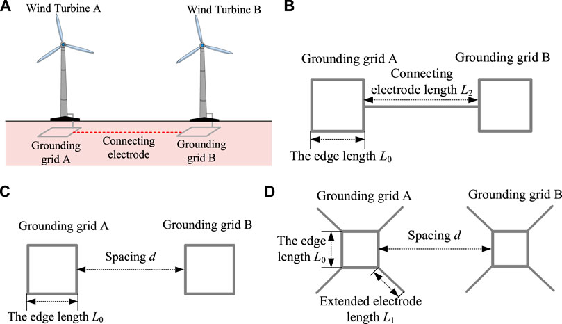
FIGURE 1. Schematic diagram of the nearby wind turbine grounding grid. (A) Nearby wind turbine grounding grid connection. (B) Grounding grid connection. (C) Box grounding grid. (D) Box extension grounding grid.
In the grounding grid, the edge length L0 of the box grounding electrode is 10 m. For the traditional box extension grounding grid model, extended grounding electrodes with a length of L1 are located at the four corners of the grounding grid. For the proposed grounding grid connection model, the grounding grids of two wind turbines are connected by grounding the electrode with a length of L2. It should be noted that the connecting electrode in Figure 1B and the extended grounding electrode in Figure 1D belong to the extended grounding electrode of the grounding grid. When setting the simulation parameters, the total length L of extended grounding electrodes of different grounding grids should be kept equal, that is, L = L2 = 8*L1. The grounding electrodes are buried in soil with a depth of 0.8 m. To simulate the practical lightning impulse grounding characteristics of the abovementioned three grounding grids, a current of 40 kA is applied to the grounding grid for the amplitude of most lightning currents in nature is between 16 and 40 kA.
Metallic materials are commonly applied in the grounding grid. Owing to their high magnetoconductivity, the skin effect and inductance effect will be intense, resulting in a high impulse grounding impedance. Compared with metal grounding materials, flexible graphite composite materials have stable physical and chemical properties, low magnetoconductivity, and good electrical conductivity (Hu et al., 2014). The impulse grounding impedance can be smaller. To compare their grounding characteristics, galvanized steel and flexible graphite composite grounding materials are selected. The diameter of galvanized steel and the flexible graphite electrode is 16 and 28 mm, respectively. The relative resistivity of galvanized steel and the flexible graphite electrode is 109.7 and 1857.1, respectively, while the relative permeability is 636 and 1, respectively. As a 10 kHz current flows through the abovementioned two grounding electrodes, their skin depths are 0.277 and 28.692 mm, respectively.
Simulation and Analysis on the Grounding Resistance Reduction Method of the Wind Turbine
The grounding characteristics of the wind turbine grounding grid are related to many factors, such as the grounding material, extended grounding electrode length, soil resistivity, and grounding current frequency. In order to characterize the influence of a certain factor on wind turbine grounding resistance, the resistance reduction efficiency η is introduced. Resistance reduction efficiency η is defined as Eq.1
where R0 is the primary grounding resistance with no resistance reduction method, Ω, and Ri is the grounding resistance with the resistance reduction method, Ω.
The grounding grids of different structures are composed of galvanized steel or flexible graphite. According to the number of grounding grids in Figure 1 and the grounding material, the grounding resistance R and the resistance reduction coefficient η are expressed in different forms. Among them, the grounding resistances of the grounding grid connection with galvanized steel and flexible graphite are respectively represented by Rbs and Rbg, and the corresponding resistance reduction efficiencies are represented by ηbs and ηbg; the grounding resistances of the box grounding grid with galvanized steel and flexible graphite are respectively represented by Rcs and Rcg, and the corresponding resistance reduction efficiencies are represented by ηcs and ηcg; the grounding resistances of the box extension grounding grid with galvanized steel and flexible graphite are respectively represented by Rds and Rdg, and the corresponding resistance reduction efficiencies are represented by ηds and ηdg.
Effect of Extended Grounding Electrode Length
To study the effect of extended grounding electrode length on grounding resistance reduction of the wind turbine grounding grid, the extended grounding electrode length L is taken as 0–100 m. The soil resistivity is 500 Ω m, and the grounding current frequency is 50 Hz. Both the traditional box extension grounding grid model and the proposed grounding grid connection model are applied with galvanized steel and the flexible graphite material. The grounding resistance and resistance reduction efficiency calculation results are shown in Figure 2.
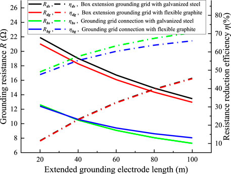
FIGURE 2. Grounding resistance and resistance reduction efficiency under different extended grounding electrode lengths.
The grounding resistances of galvanized steel and the flexible graphite box grounding grid are 24.75 and 23.72Ω, respectively. As shown in Figure 3, the wind turbine grounding resistance decreases gradually with the increase of extended length. With the same extended length, the grounding resistance of the grounding grid connection method is smaller.
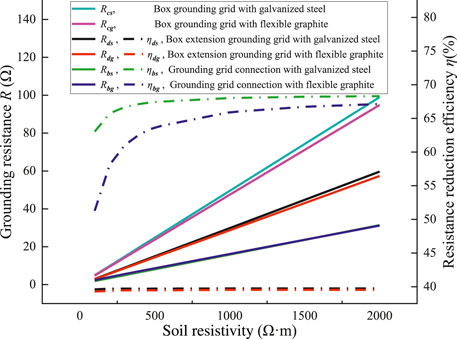
FIGURE 3. Grounding resistance and resistance reduction efficiency under different soil resistivities.
When the box extension grounding grid scheme is adopted or the grounding electrode length L2 of the grounding grid connection is less than 40m, the grounding resistance of the flexible graphite grounding grid is smaller. However, when the grounding electrode length L2 of the grounding grid connection is more than 40 m, the grounding resistance of the galvanized steel grounding grid is lower. This is because when the size of the grounding grid is relatively small, the volume of the grounding conductor occupies a large proportion of the entire grounding system. A larger-diameter flexible graphite grounding electrode is conducive to current dispersion to the soil. In a large grounding grid, the volume of the grounding conductor accounts for a small proportion of the entire grounding system, and the low-resistivity galvanized steel is more conducive to current dispersion to the soil.
It can also be seen from Figure 2 that the grounding resistance reduction efficiency of the grounding grid connection method is higher than that of the box extension grounding grid method. Besides, the grounding resistance reduction efficiency increases with the extended grounding electrode length but shows a saturated tendency. When the connecting grounding electrode length is 100 m, the resistance reduction efficiency of the galvanized steel grounding grid and flexible graphite grounding grid is 70.55 and 66.06%, respectively. However, as the connecting grounding electrode length is increased from 80 to 100 m, the resistance reduction efficiency of the galvanized steel grounding grid and flexible graphite grounding grid is increased by less than 5%. This is mainly because the current dispersion length of the connecting grounding electrode has a certain limit. As the effective current dispersion length is reached, a longer connecting electrode length cannot significantly improve the resistance reduction efficiency.
Effect of Soil Resistivity
There are great differences in soil resistivity under different geological terrain areas. The corresponding requirements for wind turbine grounding resistance are also different (Alipio et al., 2019; Salarieh et al., 2020). In order to study the effect of soil resistivity on the grounding resistance reduction of the wind turbine, the soil resistivity is set to 100–2000 Ω m. Moreover, the extended grounding electrode length L is 80m, and the current frequency is 50 Hz. The grounding resistance and resistance reduction efficiency of grounding grids under different soil resistivities are shown in Figure 3.
As the soil resistivity is 100 Ω m, there is little difference between the grounding resistance of the traditional box extension grounding grid and the proposed grounding grid connection for good current dispersion characteristics in the soil. With the increase of soil resistivity, the current dispersion in soil becomes difficult. Under the same high-soil resistivity conditions, the grounding resistance of the grounding grid connection is about 50% of that of the box extension grounding grid.
The resistance reduction efficiency of the box extension grounding grid is constant at about 40%, while the resistance reduction efficiency of the grounding grid connection increases from 51 to 68% with a soil resistivity of 100–2000 Ω m. Under the same soil conditions, the resistance reduction efficiency of the grounding grid connection is obviously higher than that of the box extension grounding grid.
In the connected grounding grids, the resistance reduction efficiency of the galvanized steel grounding grid is higher than that of the flexible graphite grounding grid, but the difference gradually decreases with the increasing soil resistivity. Under a soil resistivity of 100–1500 Ω m, the grounding grid made of low-resistivity galvanized steel has a larger current dispersion ability to the far end. However, high soil resistivity can intensify the end effect of the grounding electrode, which makes more current tend to disperse from the far end into the soil. Thus, the effect of the grounding material on grounding resistance reduction decreases in areas with high soil resistivity.
Effect of Grounding Current Frequency
In nature, more than 90% of lightning current energy is concentrated within 20 kHz. In order to study the effect of grounding current frequency on wind turbine grounding characteristics (Chen and Du, 2019; Sekioka, 2019), a DC current, a power frequency current, an AC current of 10 kHz, and a standard lightning current of 2.6/50 μs were applied. The current amplitude is 40 kA, the soil resistivity is 500 Ω m, and the extended grounding electrode length L is 80 m. The grounding resistance of two grounding grids under different grounding current frequencies is calculated, as shown in Figure 4.
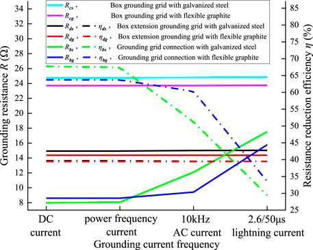
FIGURE 4. Grounding resistance and resistance reduction efficiency under different grounding current frequencies.
As shown in Figure 4, under different grounding current frequencies, the grounding resistance of the box grounding grid composed of galvanized steel and flexible graphite is constant at 24.8 and 23.7 Ω, respectively, and the grounding resistance of the box extension grounding grid composed of galvanized steel and flexible graphite is constant at 15 and 14.4 Ω, respectively. This is because the size of the grounding grid is relatively small so that the current at different frequencies can be fully dispersed in the grounding grid.
With an increase in grounding current frequency, the grounding resistance of connected ground grids increases. The flexible graphite grounding grid has lower grounding resistance than the steel one. It is caused by the weaker inductance effect, the skin effect, and better dispersion properties of the flexible graphite grounding electrode with lower magnetoconductivity.
It can also be seen from Figure 4 that the resistance reduction efficiency of the box extension grounding grid is constant at 40% under different grounding current frequencies. The resistance reduction efficiency of connected grounding grids varies with the grounding material and grounding current frequency. As the grounding current frequency increases, the resistance reduction efficiency of connected grounding grids decreases. Under DC or power frequency current, the resistance reduction efficiency of the grounding grid is greater than 62%, which is higher than that of the box extension grounding grid; under the AC current of 10 kHz, the resistance reduction efficiency of the flexible graphite grounding grid is higher than that of the galvanized steel grounding grid; under the standard lightning current of 2.6/50 μs, the large high-frequency component of lightning current causes a great inductance effect and skin effect of the grounding electrode, leading to a smaller resistance reduction efficiency of connected grounding grids.
Ground Potential Rise of the Grounding Conductor of the Grounding Grid Connection
The current dispersion in the grounding grid determines the potential distribution of the grounding conductor. In order to analyze the grounding characteristics and GPR of the grounding conductor of the three grounding grids shown in Figure 1, the edge length of the grounding grid L0 is 10 m, and the quad-angle extended grounding electrode L1 is 10 m. The connecting grounding electrode L2 and the grounding grid spacing d are 80 m. Galvanized steel grounding grids are buried in the soil with a resistivity of 500 Ω m. The power frequency grounding current of 40 kA is applied to wind turbine A. The grounding resistance results are shown in Table 1.
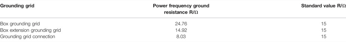
TABLE 1. Grounding resistance of three grounding grids.
As shown in Table 1, with the increasing grounding grid area, the grounding resistance decreases. The grounding resistance of the box grounding grid with the smallest grounding current dispersion area is 24.76 Ω, which is higher than the standard value of 15 Ω. The grounding resistance of the box extension grounding grid and the grounding grid connection is less than the standard value, and the minimum grounding resistance of the grounding grid connection is only 8.03 Ω. Due to more current flowing into the soil, the GPR of the grounding conductor decreases with the increasing grounding grid area. The maximum GPR of the box grounding grid is 995 kV. By adding an auxiliary extended grounding electrode, the maximum GPR value can be reduced to 598 kV, with a decrease of 39.9%. Meanwhile, the induced voltage of the wind turbine B grounding grid is 35.7 kV. The grounding grid connection further increases the current dispersion area so that the maximum GPR of the wind turbine A grounding grid is 322 kV, and the maximum GPR of the wind turbine B grounding grid is 302 kV. Therefore, the GPR of the wind turbine B grounding grid does not exceed the insulation level of the wind turbine at the same voltage level.
According to the abovementioned analysis, we can infer that when the voltage level or insulation level of wind turbines is close, the current dispersion from the lightning-struck wind turbine will not cause the back flashover of the connected wind turbine. With the increase of distance between adjacent wind turbines and the decrease of soil resistivity, the influence will be further reduced. Therefore, the grounding grid connection structure is conducive to reducing the GPR of the grounding grid and the lightning potential at the wind turbine top.
Conclusion
In this article, the grounding characteristics of the grounding grid connection and the box extension grounding grid are compared. The current dispersion effect of galvanized steel and the flexible graphite composite grounding electrode is analyzed. The GPRs of the grounding grid connection are studied. The conclusions are as follows:
1) Under the power frequency current, the grounding resistance of the grounding grid connection is smaller than that of the box and box extension grounding grid. The grounding resistance of the grounding grid decreases with the increase of the extended grounding electrode length and the decrease of soil resistivity. As the connecting grounding electrode length L2 exceeds 80m, the resistance reduction of the grounding grid gradually slows down; as the soil resistivity exceeds 1000 Ω m, the resistance reduction efficiency of the grounding grid connection is nearly saturated and constant at about 68%.
2) The higher the grounding current frequency, the more obvious the advantage of the flexible graphite composite grounding grid dispersing current to the far end. Meanwhile, the high-frequency grounding current limits the grounding reduction efficiency of the grounding grid connection.
3) The grounding grid connection increases the current dispersion area, making the GPR of the grounding conductor lower than that of the box extension grounding grid. When the voltage level or insulation level of wind turbines is close, the current dispersion of the lightning-struck wind turbine will not cause the back flashover of connected wind turbines.
Data Availability Statement
The original contributions presented in the study are included in the article/Supplementary Material, and further inquiries can be directed to the corresponding author.
Author Contributions
YH: conceptualization, writing—original draft preparation, and simulation; ZL: software and grounding test; TH: software and grounding test; YA: project administration and data arrangement; WS: supervision; SH: supervision and proofreading; CM: drawing; BA: figures; DC: revision.
Funding
This work was supported by the Natural Science Foundation of China under Grant 51807113, the Shandong Provincial Natural Science Foundation, China (ZR2021ME092), the Jiangsu Provincial Natural Science Foundation, China (SBK2020042717), and the China Southern Power Grid Science and Technology Project(CSGULAEMEST-2021-KF-05).
Conflict of Interest
TH and WS were employed by the company State Grid Jiangsu Electric Power Co., Ltd. SH was employed by the company China Southern Power Grid.
The remaining authors declare that the research was conducted in the absence of any commercial or financial relationships that could be construed as a potential conflict of interest.
Publisher’s Note
All claims expressed in this article are solely those of the authors and do not necessarily represent those of their affiliated organizations or those of the publisher, the editors, and the reviewers. Any product that may be evaluated in this article or claim that may be made by its manufacturer is not guaranteed or endorsed by the publisher.
References
Alipio, R., Conceição, D., De Conti, A., Yamamoto, K., Dias, R. N., and Visacro, S. (2019). A Comprehensive Analysis of the Effect of Frequency-dependent Soil Electrical Parameters on the Lightning Response of Wind-Turbine Grounding Systems. Electric Power Syst. Res. 175, 105927. doi:10.1016/j.epsr.2019.105927
Alipio, R., De Conti, A., Duarte, N., and Correia de Barros, M. T. (2021). Bare versus Insulated Conductors for Improving the Lightning Response of Interconnected Wind Turbine Grounding Systems. Electric Power Syst. Res. 197, 107320. doi:10.1016/j.epsr.2021.107320
Caetano, C. E. F., Lima, A. B., Paulino, J. O. S., Boaventura, W. C., and Cardoso, E. N. (2018). A Conductor Arrangement that Overcomes the Effective Length Issue in Transmission Line Grounding. Electric Power Syst. Res. 159, 31–39. doi:10.1016/j.epsr.2017.09.022
Chen, H., and Du, Y. (2019). Lightning Grounding Grid Model Considering Both the Frequency-dependent Behavior and Ionization Phenomenon. IEEE Trans. Electromagn. Compat. 61 (1), 157–165. doi:10.1109/TEMC.2017.2789210
Gao, Z., Cao, X., and Du, J. (2018). Study on the Effect of Vertical Rod on Reducing Tower's Impulse Grounding Resistance[J]. High Voltage Apparatus 54 (04), 182–187. doi:10.13296/j.1001-1609.hva.2018.04.027
Hu, Y., Ruan, J., Gong, R., et al. (2014). Flexible Graphite Composite Electrical Grounding Material and its Application in tower Grounding Grid of Power Transmission System[J]. Power Syst. Tech. 38 (10), 2851–2857. doi:10.13335/j.1000-3673.pst.2014.10.037
Hu, Y., Ruan, J., Xiao, W., et al. (2016). Study on Flexible Graphite Composite Material for Electrical Grounding and its Correlation Experimentations[J]. High Voltage Eng. 42 (06), 1879–1889. doi:10.13336/j.1003-6520.hve.20160616028
Kuklin, D. (2016). Choosing Configurations of Transmission Line tower Grounding by Back Flashover Probability Value. Front. Energ. 10 (2), 213–226. doi:10.1007/s11708-016-0398-6
Li, J., Jiang, J., and Li, L. (2013). Simulation and experiment Study on Resistance-Reducing Mechanism of Grounding Device with Spicules[J]. Power Syst. Tech. 37 (01), 211–217. doi:10.13335/j.1000-3673.pst.2013.01.037
Salarieh, B., De Silva, H. M. J., and Kordi, B. (2020). Electromagnetic Transient Modeling of Grounding Electrodes Buried in Frequency Dependent Soil with Variable Water Content. Electric Power Syst. Res. 189, 106595. doi:10.1016/j.epsr.2020.106595
Sekioka, S. (2019). Frequency and Current-dependent Grounding Resistance Model for Lightning Surge Analysis. IEEE Trans. Electromagn. Compat. 61, 419–425. doi:10.1109/temc.2018.2829923
Shen, X., and Pongsathorn, R. (2021). Pedestrian-aware Statistical Risk Assessment. IEEE Trans. Intell. Transportation Syst., 1-9. doi:10.1109/tits.2021.3074522
Shen, X., Zhang, Y., and Kota, S. (2020). Gaussian Mixture Model Clustering-Based Knock Threshold Learning in Automotive Engines. IEEE/ASME Trans. Mechatronics 25(6):2981-2991. doi:10.1109/tmech.2020.3000732
Shen, X., Zhang, Y., and Tielong, S. (2017). Spark advance Self-Optimization with Knock Probability Threshold for Lean-Burn Operation Mode of SI Engine. Energy 122 (MAR.1), 1–10. doi:10.1016/j.energy.2017.01.065
Sun, J., Tian, X., Li, Y., Wu, Y., Duan, Y., Chen, J., et al. (2021). Lightning Strike-Induced Dynamic Conduction Characteristics and Damage Behavior of Carbon Fiber-Reinforced Polymer Composites. Compos. Structures 275, 114391. doi:10.1016/j.compstruct.2021.114391
Taha, M. A., Li, L., and Wang, P. (2020). Estimation Performance of the Lightning protection System in an Urban 110 kV Grounding Grid Substation. Results Eng. 6, 100140. doi:10.1016/j.rineng.2020.100140
Wu, J., Zhang, B., He, J., and Zeng, R. (2014). Optimal Design of tower Footing Device with Combined Vertical and Horizontal Grounding Electrodes under Lightning. Electric Power Syst. Res. 113, 188–195. doi:10.1016/j.epsr.2014.03.021
Yuan, T., Lei, C., and Sima, W. (2012). Analysis of Grounding Resistance Reduction Effect Based on Enhancing Impulse Current Leakage Efficiency[J]. Trans. China Electrotechnical Soc. 27 (11), 278–284. doi:10.19595/j.cnki.1000-6753.tces.2012.11.037
Zhang, B., He, J., and Zeng, R. (2015). State of Art and Prospect of Grounding Technology in Power System[J]. High Voltage Eng. 41 (8), 2569–2582. doi:10.13336/j.1003-6520.hve.2015.08.010
Keywords: wind turbine, grounding grid connection, grounding resistance, ground potential rise, grounding resistance reduction
Citation: Hu Y, Liu Z, Huang T, An Y, Shen W, Hu S, Ma C, An B and Chen D (2022) A New Grounding Resistance Reduction Method for Wind Turbines by Grounding Grid Connection in Limited Areas. Front. Energy Res. 10:830628. doi: 10.3389/fenrg.2022.830628
Received: 07 December 2021; Accepted: 14 March 2022;
Published: 13 April 2022.
Edited by:
Xun Shen, Tokyo Institute of Technology, JapanReviewed by:
Xiaohan Shi, Shandong University, ChinaMing-Xiao Zhu, China University of Petroleum Huadong, China
Copyright © 2022 Hu, Liu, Huang, An, Shen, Hu, Ma, An and Chen. This is an open-access article distributed under the terms of the Creative Commons Attribution License (CC BY). The use, distribution or reproduction in other forums is permitted, provided the original author(s) and the copyright owner(s) are credited and that the original publication in this journal is cited, in accordance with accepted academic practice. No use, distribution or reproduction is permitted which does not comply with these terms.
*Correspondence: Yunzhu An, anyunzhu2006@163.com