 Chao Xing
 Junhao Chen1,2
- 1Electric Power Research Institute, Yunnan Power Grid Co., Ltd., Kunming, China
- 2School of Electric Power Engineering, Kunming University of Science and Technology, Kunming, China
When traditional STATCOM (Static Synchronous Compensator) performs large-capacity reactive power compensation, the control accuracy of the DC side voltage will be affected and the DC side voltage will fluctuate greatly. Therefore, this study proposes to use battery energy storage STATCOM (STATCOM/BESS) and gives the main circuit topology of STATCOM/BESS. By analyzing the working principle of STATCOM/BESS, the mathematical model and control method are derived and modeled, in which the Shepherd model is used as the energy storage battery in STATCOM/BESS. Aiming at the possible imbalance of the battery state of charge (SOC) in STATCOM/BESS, the phase-to-phase SOC balance control and phase control are proposed. At last, in PSCAD/EMTDC simulation software, STATCOM/BESS is tested for dynamic response and steady-state response performance of active power control, reactive power control, and transformation failure suppression test, which verifies the effectiveness and superiority of STATCOM/BESS commutation failure.
Introduction
High Voltage Direct Current (HVDC) plays an important role in China’s strategy of “West-East electricity transmission project and national network” by virtue of its advantages in long-distance and large-capacity power transmission and grid interconnection (Zhang et al., 2010). In HVDC transmission projects put into operation in China, the characteristics of “strong HVDC and weak AC, multi-infeed DC” are increasingly prominent, which leads to the safety, stability, and reliability of the power grid (Wang et al., 2018). When a fault occurs at the receiving end of the HVDC system, it is easy to cause the voltage sag of the AC busbar at the inverter side, leading to commutation failure of the HVDC system. STATCOM can realize dynamic reactive power compensation, suppress the bus voltage flicker, and improve the voltage transient stability of the system. When the traditional STATCOM performs high-capacity reactive power compensation, the control accuracy of the outer DC side voltage will be affected, leading to the DC side voltage oscillation and large amounts of harmonic components in the output current. At this time, the traditional STATCOM only compensates for the reactive power, and its supporting effect on the grid voltage will be not ideal (Li et al., 2014).
STATCOM by itself has no ability to control and compensate active power, and the energy-storage STATCOM combined with reactive power compensation technology can make up for the deficiency of traditional STATCOM in HVDC system applications (Authors Anonymous, 2016). At present, the energy storage in the field of power systems mainly includes pumped storage, flywheel energy storage, supercapacitor, and battery energy storage (Cheng et al., 2007). In the study of Castaneda et al. (2010), energy-storage STATCOM was applied to the grid-connected wind power planning, which effectively avoids voltage collapse in case of sudden failure and shorts the voltage recovery time. Yang et al. (2001) proposed a STATCOM/BESS device with parallel batteries on the DC side of STATCOM to improve the dynamic and transient stability and power transmission capacity of the system. Xie et al. (2009) studied the effect of energy-storage STATCOM on suppressing voltage phase change in the weak power grid. Through experiments and simulations, it is found that when the system fails, compared with traditional STATCOM, energy-storage STATCOM can suppress voltage phase transformation and reduce voltage sag by 7%. For the study of the topology and control method of energy storage type STATCOM, a static reactive generator/battery energy storage (STATCOM/BESS) integrated system consisting of high-pressure-resistant, high-power, and low-switching switching devices such as GTO, IGBT, and so on is designed (Fei et al., 2005), which can compensate for the power loss of the system itself while improving the system’s compensation capacity, thus damping oscillation and improving the system’s temporary stability. Compared with traditional STATCOM, STATCOM/BESS integrated system can effectively reduce fault voltage landing and significantly suppress oscillations during voltage recovery.
In this study, according to the existing research results and the actual system requirements, a STATCOM/BESS with an angle cascaded H-bridge structure is carried out, and the performance of the designed STATCOM/BESS is verified by simulation.
STATCOM/BESS Topology and Mathematical Model
DC/DC Section
Energy storage batteries are connected to the DC side in direct parallel connection, non-isolated two-way DC/DC connection, isolated two-way DC/DC connection, and so on. Isolated two-way DC/DC connection requires a low- or high-frequency transformer for boost, which is large in volume and high in cost (Fei et al., 2005; Xie et al., 2009; He, 2016). The non-isolated bi-directional DC/DC connection has a simple structure, is of low cost, and has good energy conversion efficiency. Its disadvantages are that the adjustment range of input and output is small and there is no electrical isolation between the battery pack and the power grid (Li et al., 2021).
The actual STATCOM/BESS phase contains 36/42 cascade H bridge modules, which is a large number. Therefore, considering the cost and technical difficulty of the device, the parallel capacitor of the energy storage battery is directly connected to the DC side of STATCOM, in which the parallel capacitor plays the role of energy buffer and flattens the power difference between the H bridge module and energy storage battery module.
DC/AC Section
In the conventional low-voltage distribution network, the DC/AC part of STATCOM usually adopts the low-voltage two-level topology. However, due to its low-voltage grade, high switching device frequency, and large loss, the multi-level topology is usually adopted in the HVDC transmission system (Shen and Raksincharoensak, 2021a). STATCOM/BESS uses the multilevel topology to make the output waveform have a better harmonic spectrum, and the voltage stress borne by each switching device is smaller, effectively reducing the capacity and voltage level of each battery pack (Li et al., 2014).
Figure 1 shows the angle-cascaded H-bridge STATCOM/BESS topology (Shen et al., 2022). There is a zero-sequence current in the angle structure, which can exchange active power between three-phase bridge chains. Several H-bridge submodules are cascaded to form a bridge chain. Each H-bridge submodule can output three levels of voltage, and the bridge chain series reactor can be directly integrated into the grid and withstand the gridline voltage. When the number of H-bridge sub-modules is n, 2n+1 levels can be output through modulation, and the AC side output of the converter is a multi-level waveform, so changing the number of H-bridge sub-modules can change the output voltage of the converter (He, 2016). Compared with the diode clamp three-level topology and capacitor clamp three-level topology, the cascaded H-bridge topology has a simple structure and convenient maintenance, requiring only the minimum number of components in the case of the same number of output levels (Cui et al., 2011), and avoiding the problem of unbalanced charge and discharge when multiple battery groups are connected in series.

FIGURE 1. STATCOM/BESS topology.
Based on the above considerations, this study adopts the angle-cascaded H-bridge topology.
STATCOM/BESS Working Principle
The H-bridge-cascaded STATCOM/BESS each phase bridge chain can be directly integrated into the power grid after series reactor L. The network between each phase bridge chain and the connection point is equivalent to the two-terminal network as shown in Figure 2A; Yang et al., 2022. Each phase bridge chain can be regarded as a controllable voltage source, with output voltage UA, connection point grid US, and internetwork current IA. By controlling the amplitude and phase angle of the output voltage UA, mutual compensation of the active and reactive power between STATCOM/BESS and the power grid is realized.
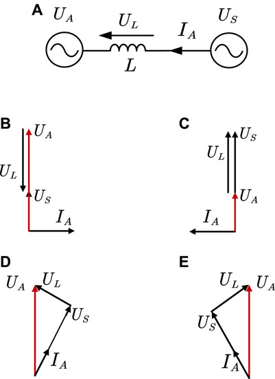
FIGURE 2. Schematic diagram of power regulation.
In Figure 2B, the grid voltage at the US grid-connected point controls UA and US in the same direction and makes UA amplitude greater than US amplitude. At this point, STATCOM/BESS sends perceptual reactive power to the grid. In Figure 2C, the UA is controlled in the same direction as the US, and the UA amplitude is smaller than the US amplitude. At this time, the STATCOM/BESS sends capacitive reactive power to the grid. In Figure 2D, the UA phase is controlled to lead the US phase, and the STATCOM/BESS sends active power to the grid at this time. In Figure 2E, the UA phase is controlled to lag BEHIND US phase, at which time STATCOM/BESS absorbs active power from the grid. By controlling the amplitude and phase angle of the output voltage UA, STATCOM/BESS, and the power grid can complement each other with active and reactive power.
The STATCOM/BESS Mathematical Model
Assuming that the parameters of each phase of the angle cascade STATCOM/BESS are completely consistent, one three-phase STATCOM can be decomposed into three single-phase STATCOM to facilitate the analysis and derivation of the mathematical model. Taking the AB phase as an example, its single-phase equivalent circuit is shown in Figure 3; Shen et al., 2020.
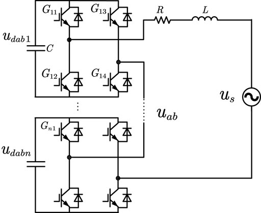
FIGURE 3. Single-phase circuit structure diagram.
According to Kirchhoff’s voltage theorem, The single-phase bridge chain voltage drop under the angle-cascaded structure is the grid-connected point line voltage us, uab is the bridge chain output voltage, and iab is the grid-connected phase current.
The H-bridge sub-module is composed of four switching devices in parallel with a DC capacitor( Yang et al., 2019). Suppose that the switch state of Gj1 is 1 when it is on and 0 when it is off. The same is true for Gj3. At this time, the difference between the switch states of Gj1 and Gj3 is used to define the switch state Hj of the entire H-bridge module; then Hj is
Eq. 3 can be used to obtain the current icj of the DC container in parallel with the jth H bridge sub-module:
According to Eq. 3, the state equation of the capacitor voltage can be obtained, where udabj is the capacitor voltage of the jth H bridge module on the AB bridge chain:
Define the sum of the switching states of the H bridge at all levels as the switching state N of the phase converter, then
Using Eq. 6, one can obtain the output voltage of the jth H bridge sub-module uabj:
Assume that the capacitor voltages of all modules in the bridge chain are equal; then, udab is the sum of capacitor voltages of all modules in the bridge chain, and the output voltage uab of the bridge chain can be obtained by combining Eq. 5:
Combining Eq. 4, we can get
After substituting Eq. 7 into Eq. 1, we can get
Assume that the grid-connected current iab and the total capacitor voltage udab are state variables, and establish their state equation by combining Eqs 8 and 9; Shen and Raksincharoensak, 2021b. After discretization, the discrete state equation can be obtained as
where iab(k+1) and udab(k+1) indicate the AB-phase grid-connected current and bridge-chain capacitor voltage value at time (k+1), and N(k) and usab(k) indicate the AB bridge-chain switch at time k and state and grid-connected point line voltage, respectively and, Tk is the sampling period (Shen et al., 2021).
Energy Storage Element and SOC Equalization Control
Parameter Extraction of the Shepherd Model
The Shepherd model directly describes the electrochemical behavior of batteries including the port voltage, open-circuit voltage, internal resistance, discharge current, and state of charge (SOC) through an equation. The model can be used to describe the charging and discharging process of the battery. The circuit diagram of the Shepherd model is shown in Figure 4, where Eb is the no-load voltage of the battery, Ub is the output voltage of the battery, Rb is the internal resistance of the battery and ib is the output current of the battery.
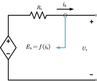
FIGURE 4. Shepherd model circuit diagram.
The nonlinear function shown in Eq. 11 describes the relationship between battery no-load voltage and output current (Zhu et al., 2020):
In Eq. 11, E0 is the voltage constant (V), K is the polarization voltage (V), Q is the battery capacity (Ah), A is the voltage constant in the exponential discharge zone (V), B is the time constant in the exponential discharge zone (Ah−1) (Zhou et al., 2016), and it = ∫ibdt is the actual cumulative output charge of the battery.
Figure 5 shows the charge and discharge waveform of the battery( Shen et al., 2017). It can be seen that the change in the battery terminal voltage can be roughly divided into three areas: exponential change area, relatively stable area, and rapid change area. The terminal voltage of the battery in the area of exponential change rises or falls with the change of charge in the form of exponential, and the corresponding voltage value of the battery in the state of full charge is Efull. When the battery runs in the relatively stable region, the terminal voltage changes slowly with the charge quantity, and the critical voltage corresponding to the transition from the exponential changing region to the relatively stable region is Eexp. In the rapidly changing region, the battery terminal voltage changes rapidly with the amount of charge, and the critical voltage corresponding to the transition from the relatively stable region to the rapidly changing region is Enom.

FIGURE 5. Typical charge and discharge waveform of a battery.
Estimation of battery internal resistance R: The internal resistance R affects the output voltage of the battery and then affects the working efficiency of the battery. Therefore, the internal resistance of the battery can be estimated by measuring the working efficiency of the battery. The working efficiency of the battery η can be easily calculated as follows (Liu et al., 2020):
where Inom is the nominal discharge current of the battery and Vnom is the nominal voltage. Typical values of the working efficiency of batteries can be obtained by statistical methods in the practical project, and the calculation equation of internal resistance R can be obtained from Eq. 13:
To determine the remaining parameters of the model, three sets of data can be obtained from the measured discharge curve given by the manufacturer: full charge voltage Efull, exponential area boundary voltage Eexp, discharge capacity Qexp, stable discharge area boundary voltage Enom ,and boundary capacity Qnom.
The exponential zone discharge voltage time constant A can be determined by Eq. 14:
The exponential zone discharge voltage time constant B can be determined by Eq. 15:
After extracting the parameters A and B, the polarization voltage K can substitute the first group of data and the third group of data in Eq. 11 to obtain Eq. 16:
Finally, the voltage time constant E0 can be derived from the full charge voltage Efull to obtain Eq. 17:
SOC Equalization Control
There are many chained STATCOM/BESS modules, which may lead to different charge and discharge times of each phase energy storage battery and sub-module batteries in the phase. Especially when the grid-connected voltage is not symmetrical, the disequilibrium of charge and discharge between energy storage batteries will be more serious, reducing the efficiency of energy storage batteries. Therefore, a state of charge (SOC) equalization control strategy for STATCOM/BESS is proposed, as shown in Figure 6; Yang et al., 2021a.
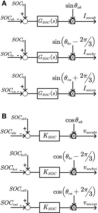
FIGURE 6. STATCOM/BESS SOC equalization control: (A) phase-to-phase SOC equalization control and (B) in-phase sub-module SOC equalization control.
In Figure 6A, SOCab-SOCca is the SOC of each phase, SOC0 is the average SOC of the phase, and are calculated using Eqs 18 and 19, respectively:
The basic idea of phase-to-phase SOC equalization control is as follows: the difference between each phase SOCm and the phase average SOC0 passes through the PI controller Gsoc(s) to obtain the phase SOC equalization active current command Isocm (Yang et al., 2021b), which is then sent to the current inner loop control. If the SOCm is less than SOC0, a positive active power command is obtained, and the energy storage battery of this phase is in the state of charge as a whole so that the SOCm increases and the SOC balance of the phase is achieved, and vice versa.
In Figure 6B, SOCmi is the SOC of the sub-module battery in the phase and SOCm0 is the average SOC of the sub-module battery in the phase. The basic idea of SOC control of sub-module in phase is as follows (Yang et al., 2018): If SOCmi is greater than SOCm0, then the difference value is proportionally controlled to obtain the submodule SOC to adjust the additional modulation signal vsocmi. Since vsocmi is ahead of the line voltage corresponding to the link, the submodule will output active power to the grid and SOCmi decreases so as to achieve the SOC balance of the submodule, and vice versa.
System Control Strategy
The goal of the STATCOM/BESS control system is to maintain a stable phase transformation voltage and reduce the probability of its occurrence when it detects that the commutation failure of the DC transmission system may occur (Zhang et al., 2021). In order to suppress commutation failure of the DC transmission system, after STATCOM/BESS detects the AC system failure, it switches the corresponding control strategy according to the severity of the failure and proposes the STATCOM/BESS power coordinated control method. When the AC system fails, STATCOM/BESS performs fast with reasonable compensation of reactive and active power, provides effective voltage support to the receiving end power grid, and effectively suppresses the occurrence of commutation failure. The power coordination control system is shown in Figure 7, Feng et al., 2021.
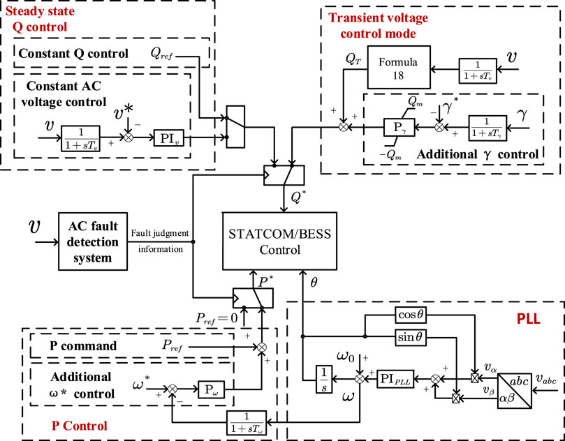
FIGURE 7. Power coordinated control system.
On the basis of receiving the upper active power command, the active power control module adds active power adjustment control based on frequency deviation, which can enhance the damping of the interconnected system and suppress power oscillation (Qi et al., 2006); the active power command is set to 0 under fault conditions and reactive power control The module starts to work, including steady-state constant reactive power control and constant AC voltage control, while the transient voltage control mode is based on the dynamic reactive power support based on voltage sag, with additional DC transmission system inverter station shutting-off the angle control.
It can provide more reactive power compensation for the grid under fault conditions to ensure the normal progress of the phase transformation process. The dynamic reactive power QT injected into the grid by STATCOM/BESS should track the voltage changes at the grid-connected point in real time, and satisfy the following equation (Oghorada et al., 2021):
In the equation, v represents the STATCOM/BESS grid-connected point voltage per unit value, IN represents the STATCOM/BESS rated current, vmax and vmin, respectively, represent the upper and lower limits of the bus voltage at the grid-connected point during the dynamic reactive power support process, and kT1 represents the reactive power proportional coefficient in the process of dynamic reactive power compensation.
Simulation Analysis
In this study, PSCAD/EMTDC software is used to build the electromagnetic transient simulation model. The overall framework of the electromagnetic transient model is shown in Figure 8. In the model, the main circuit of the LCC-HVDC system adopts the single-pole 12 pulse structure, and the main parameters are selected by referring to Yongfu DC Project, as shown in Table 1. The DC control system is the same as the controller in the CIGRE standard model.
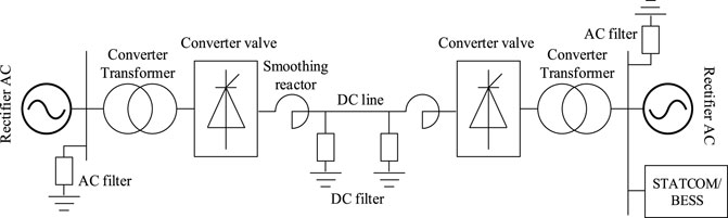
FIGURE 8. LCC-HVDC simulation system.
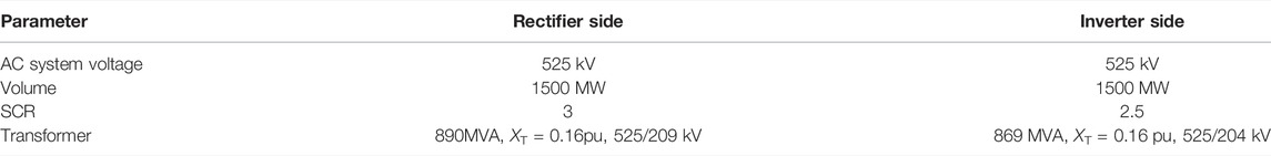
TABLE 1. LCC-HVDC system parameters.
Limited by the simulation speed, the STATCOM/BESS electromagnetic transient simulation model in this article is equipped with three H-bridge modules per phase, with a total capacity of 150 Mvar, which is connected to the LCC-HVDC inverter side AC bus through a 35/525 kV transformer.
Active and Reactive Power Control
The response performance of STATCOM/BESS is simulated. The STATCOM output active power instruction is set as 60 MW and reactive power instruction as 60 Mvar, respectively, and the output power changes are observed. Figure 9A shows the constant active power control power response graph. During the dynamic response process, the active power output by STATCOM quickly follows the active command; the rise time is about 0.18 s, the maximum output is 66 MW, and the overshoot is less than 11%. In the steady-state process, the active power output by STATCOM fluctuates between 59 and 61.5 MW, and the steady-state response error is less than 3%. Figure 9B shows the power response diagram of constant reactive control. Its dynamic response process is also good, with a rising time of 0.178 s, a maximum output value of 67.6 Mvar, and an overshoot of less than 13%. It enters the steady state at 0.24 s. The STATCOM output reactive power fluctuates between 58 Mvar and 62.5, and the steady-state response error is less than 5%. The simulation results show that the STATCOM/BESS used in this study has good output performance and can respond quickly to a given power command.
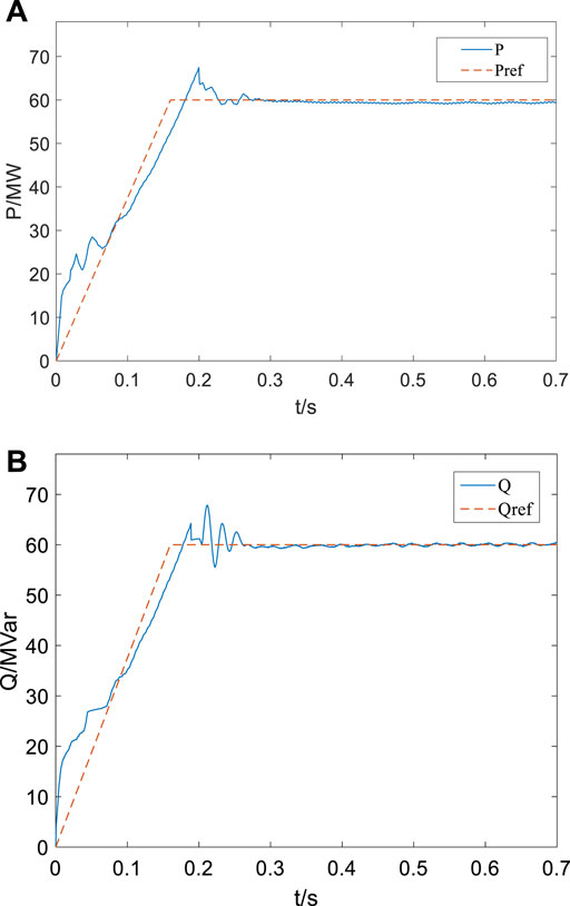
FIGURE 9. Power output response diagram: (A) active power output response diagram and (B) reactive power output response diagram.
Single-Phase Ground Fault
When the setting is 2 s, a single-phase ground fault occurs in the AC system on the inverter side and the fault lasts for 0.2 s. Figure 10 shows the effective value of the AC voltage on the inverter side before and after the fault, the extinction angle of commutation failure, the transmission power of the system, and the DC. In Figure 10A, when STATCOM is not connected, the AC voltage on the inverter side drops to 0.7 pu after the fault occurs and basically recovers to 0.96 pu after 2.5 s. After STATCOM is connected, the voltage sag is reduced to 0.83 pu, and the recovery is increased to 0.96 pu, reducing the impact of faults on the AC system. In Figure 10B, when STATCOM is not connected, the extinction-angle γ decreases to 0° after the fault occurs, indicating that the first commutation failure occurs. After STATCOM access, the extinction-angle γ is about 10°, and commutation failure is inhibited. In Figures 10C,D, when STATCOM is not connected, the power transmitted by the system drops dramatically and the DC increases sharply, seriously affecting the system operation and equipment safety. After STATCOM is connected, the transmission power and DC voltage of the system are less affected by the fault and will be stabilized in a short time. According to this group of simulation, when a single-phase grounding short-circuit occurs on the inverter side, voltage sag will occur, which will lead to commutation failure. After STATCOM/BESS is connected, the terminal voltage can be effectively supported, constant-extinction-angle can be improved, and the commutation failure and subsequent chain reaction caused by the fault can be inhibited.
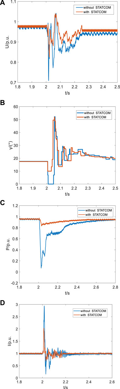
FIGURE 10. Typical characteristic quantities of single-phase faults. (A) Effective value of AC voltage on inverter side in single-phase fault. (B) Extinction angle of commutation failure in single-phase fault. (C) System transmission power in single-phase fault. (D) System DC current in single-phase fault.
Three-Phase Ground Fault
When the setting is 2 s, a three-phase ground fault occurs in the AC system on the inverter side, and the fault lasts for 0.2 s. Figure 11 shows the effective value of the AC voltage on the inverter side before and after the fault, the extinction angle of commutation failure, the transmission power of the system, and the DC current. As shown in Figure 11A, when STATCOM is not connected, AC voltage sag on the inverter side is obvious after the fault occurs, and the lowest drops to 0.5 pu, which basically recovers to 0.96 pu after 2.5 s. After STATCOM is connected, the voltage sag is reduced to 0.7 pu, and the power supply is restored more quickly. As shown in Figure 11B, when STATCOM is not connected, the extinction-angle γ decreases to 0° after the fault occurs and the first commutation failure occurs, and again to 0° at 2.15 s, indicating that continuous commutation failure occurs during the fault process.
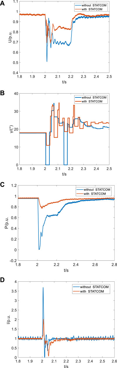
FIGURE 11. Typical Characteristic quantities of three-phase fault. (A) Effective value of the AC voltage on the inverter side in three-phase fault. (B) Extinction angle of commutation failure in three-phase fault. (C) System transmission power in three-phase fault. (D) System DC in three-phase fault.
With/Without BESS Simulation Verification
In order to compare the commutation failure suppression effect between STATCOM/BESS and conventional STATCOM, a serious single-phase grounding fault is set at 1 s in this experiment. Figures 12A,B show the AC voltage and inverter current at the inverter side of the HVDC system when an A-phase at the inverter side suddenly has a grounding fault after a period of normal operation. At this time, the system is equipped with conventional STATCOM. After the fault occurred, the A-phase voltage begin to drop, and the AC voltage on the inverter side is greatly distorted. The inverter current dropped to 0 at the same time in the vicinity of 1 s, indicating that commutation failure occurred.
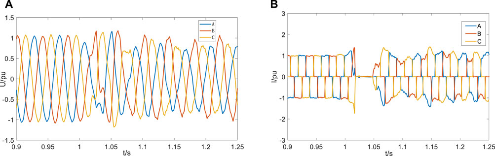
FIGURE 12. Simulation waveform diagram after installing conventional STATCOM: (A) AC voltage on the inverter side and (B) inverter current of the converter valve.
When STATCOM/BESS is installed in the system, the grounding fault occurs in A-phase in 1 s. It can be seen from Figures 13A,B that the AC voltage distortion on the inverter side is relatively small, and the phenomenon that the three-phase current is zero at the same time during the fault period does not occur, which indicates that STATCOM/BESS has restrained the occurrence of commutation failure under the single-phase fault condition.
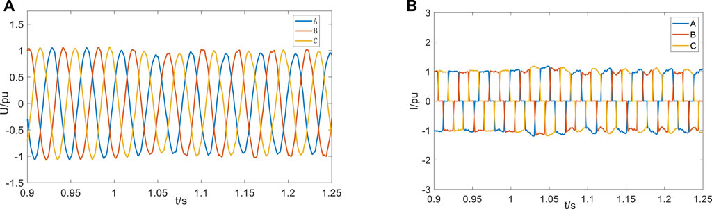
FIGURE 13. Experimental waveform diagram of installing STATCOM/BESS: (A) AC voltage on the inverter side and (B) inverter current of the converter valve.
Conclusion
In this study, the mathematical model of STATCOM/BESS is established, a suitable battery model is selected as its energy storage element, and a SOC equilibrium control strategy is put forward. The model is built in PSCAD/EMTDC simulation software and its function is tested and the following conclusions are obtained:
1) STATCOM/BESS adopts coordinated power control, which is divided into two modules: active power control and reactive power control. It can compensate active power and reactive power quickly and reasonably in case of fault.
2) Shepherd model is selected as the energy storage element, and the SOC equilibrium control strategy is proposed to improve the working efficiency of the energy storage battery.
3) Compared with the traditional STATCOM that can only compensate for reactive power, STATCOM/BESS can track active power commands and respond quickly when the active power output is required. At the same time, it can also compensate reactive power quickly when a serious fault occurs, thereby supporting the grid voltage by suppressing the commutation failure, which is of great significance in improving the operation stability of the AC/DC system with a weak receiving end.
4) The STATCOM/BESS device is installed in the single-pole 12-pulse HVDC transmission system, a single-phase ground fault is set, and a comparison experiment is carried out with the traditional STATCOM system; by comparing the two typical electrical quantities of AC voltage and inverter current, the effectiveness of the STATCOM/BESS designed in this study is verified in suppressing commutation failure.
Data Availability Statement
The raw data supporting the conclusion of this article will be made available by the authors, without undue reservation.
Author Contributions
CX was responsible for providing ideas and methods and providing an experimental platform. SC was responsible for deriving formulas, reviewing, and verifying. JC was responsible for model building, simulation, data analysis, and manuscript writing. XX, ZX, XH, and SL wrote sections of the manuscript. All authors participated in the reading and approved the submitted version.
Funding
This work was supported by the National Natural Science Foundation of China (52067009).
Conflict of Interest
CX, JC, XX, ZX, XH, and SL are employed by Yunnan Power Grid Co., Ltd.
The remaining authors declare that the research was conducted in the absence of any commercial or financial relationships that could be construed as a potential conflict of interest.
Publisher’s Note
All claims expressed in this article are solely those of the authors and do not necessarily represent those of their affiliated organizations, or those of the publisher, the editors, and the reviewers. Any product that may be evaluated in this article, or claim that may be made by its manufacturer, is not guaranteed or endorsed by the publisher.
References
Authors Anonymous, (2016). Research on Control Strategy and Application for STATCOM/BESS. Harbin, China: Harbin Institute of Technology.
Castaneda, J., Enslin, J., Elizondo, D., Abed, N., and Teleke, S. (2010). “Application of STATCOM with Energy Storage for Wind Farm Integration,” in IEEE Transmission and Distribution Conference and Exposition, New Orleans, USA, 19-22 April 2010, 1–6.
Cheng, S., Yu, W., and Wen, J. (2007). Energy Storage Technology and its Application in Power System Stability Control[J]. Power Syst. Technol. 31 (20), 97–108. doi:10.13335/j.1000-3673.pst.2007.20.009
Cui, Y., Yang, R., Gao, Q., and Xu, D. (2011). Design and Simulation of Cascaded SVG Control System[J]. High-power Convert. Technol. 5, 45–49. doi:10.13889/j.issn.2095-3631.2011.05.002
Fei, W., Zhang, Y., and Lu, Z. (2005). Integration of Large-Capacity Static Reactive Power Generator and Battery Energy Storage[J]. Automation Electr. Power Syst. 29 (10), 41–44.
Feng, S., Wu, X., Wang, Z., Niu, T., and Chen, Q. (2021). Damping Forced Oscillations in Power System via Interline Power Flow Controller with Additional Repetitive Control. Prot. Control Mod. Power Syst. 6, 21. doi:10.1186/s41601-021-00199-7
Hailian Xie, H., Angquist, L., and Nee, H.-P. (2009). Investigation of StatComs with Capacitive Energy Storage for Reduction of Voltage Phase Jumps in Weak Networks. IEEE Trans. Power Syst. 24 (1), 217–225. doi:10.1109/tpwrs.2008.2008611
He, Z. (2016). Research on the Key Technology and Application of Cascaded Multilevel Static Synchronous Compensator. Changsha, China: Hunan University.
Li, N., Yanchao, J., and Wang, J. (2014). Overview of Static Synchronous Compensator (STATCOM/BESS) with Battery Energy Storage Device[J]. New Technol. Electr. Eng. Energy 33 (4), 48–53.
Li, Z., Jiang, W., Abu-Siada, A., Li, Z., Xu, Y., and Liu, S. (2021). Research on a Composite Voltage and Current Measurement Device for HVDC Networks. IEEE Trans. Ind. Electron. 68 (9), 8930–8941. doi:10.1109/tie.2020.3013772
Liu, Y., Yang, N., Dong, B., Wu, L., Yan, J., Shen, X., et al. (2020). Multi-Lateral Participants Decision-Making: A Distribution System Planning Approach with Incomplete Information Game. IEEE Access 8, 88933–88950. doi:10.1109/access.2020.2991181
Oghorada, O. J. K., Zhang, L., Han, H., Esan, A. B., and Mao, M. (2021). Inter-cluster Voltage Balancing Control of a Delta Connected Modular Multilevel Cascaded Converter under Unbalanced Grid Voltage. Prot. Control Mod. Power Syst. 6, 23. doi:10.1186/s41601-021-00203-0
Qi, X., Zeng, D., Shi, D., Fang, X., Lan, L., Su, H., et al. (2006). Research on the Impact of UHV DC Transmission on System Security and Stability. Power Syst. Technol. 30 (02), 1–6.
Shen, X., and Raksincharoensak, P. (2021b). Statistical Models of Near-Accident Event and Pedestrian Behavior at Non-signalized Intersections. J. Appl. Statistics. doi:10.1080/02664763.2021.1962263
Shen, X., Ouyang, T., Khajorntraidet, C., Li, Y., Li, S., and Zhuang, J. (2022). Mixture Density Networks-Based Knock Simulator. IEEE/ASME Trans. Mechatron. 27, 159–168. doi:10.1109/TMECH.2021.3059775
Shen, X., Ouyang, T., Yang, N., and Zhuang, J. (2021). Sample-based Neural Approximation Approach for Probabilistic Constrained Programs. IEEE Trans. Neural Netw. Learn. Syst., 1–8. doi:10.1109/TNNLS.2021.3102323
Shen, X., and Raksincharoensak, P. (2021a). Pedestrian-aware Statistical Risk Assessment. IEEE Trans. Intell. Transp. Syst. 2021, 1–9. doi:10.1109/TITS.2021.3074522
Shen, X., Zhang, X., Ouyang, T., Li, Y., and Raksincharoensak, P. (2020). Cooperative Comfortable-Driving at Signalized Intersections for Connected and Automated Vehicles. IEEE Robot. Autom. Lett. 5 (4), 6247–6254. doi:10.1109/LRA.2020.3014010
Shen, X., Zhang, Y., Sata, K., and Shen, T. (2020). Gaussian Mixture Model Clustering-Based Knock Threshold Learning in Automotive Engines. IEEE/ASME Trans. Mechatron. 25 (6), 2981–2991. doi:10.1109/TMECH.2020.3000732
Shen, X., Zhang, Y., Shen, T., and Khajorntraidet, C. (2017). Spark Advance Self-Optimization with Knock Probability Threshold for Lean-Burn Operation Mode of SI Engine. Energy 122, 1–10. doi:10.1016/j.energy.2017.01.065
Wang, X., Hong, W., Ou, Z., Fu, Y., and Yu, J. (2018). A STATCOM Compensation Scheme to Suppress HVDC Commutation Failure[J]. Power Syst. Prot. Control 46 (05), 135–142. doi:10.7667/PSPC170230
Yang, N., Huang, Y., Hou, D., and Liu, S. (2019). Adaptive Nonparametric Kernel Density Estimation Approach for Joint Probability Density Function Modeling of Multiple Wind Farms[J]. Energies 12. doi:10.3390/en12071356
Yang, N., Ye, D., Zhou, Z., Cui, J., Chen, D., and Wang, X. (2018). Research on Modelling and Solution of Stochastic SCUC under AC Power Flow Constraints. IET Generation Transm. Distribution 12 (15), 3618–3625. doi:10.1049/iet-gtd.2017.1845
Yang, N., Huang, Y., Hou, D., Liu, S., Ye, D., Dong, B., et al. (2019). Adaptive Nonparametric Kernel Density Estimation Approach for Joint Probability Density Function Modeling of Multiple Wind Farms. Energies 12, 1356. doi:10.3390/en12071356
Yang, N., Liu, S., Deng, Y., and Xing, C. (2021b). An Improved Robust SCUC Approach Considering Multiple Uncertainty and Correlation. IEEJ Trans. Elec Electron Eng. 16, 21–34. doi:10.1002/tee.23265
Yang, N., Yang, C., Wu, L., Shen, X., Jia, J., Li, Z., et al. (2022). Intelligent Data-Driven Decision-Making Method for Dynamic Multisequence: An E-Seq2Seq-Based SCUC Expert System. IEEE Trans. Ind. Inf. 18, 3126–3137. doi:10.1109/TII.2021.3107406
Yang, N., Yang, C., Xing, C., Ye, D., Jia, J., Chen, D., et al. (2021a). Deep Learning‐based SCUC Decision‐making: An Intelligent Data‐driven Approach with Self‐learning Capabilities. IET Generation Trans Dist 16, 629–640. doi:10.1049/gtd2.12315
Yang, Z., Shen, C., Zhang, L., Crow, M. L., and Atcitty, S. (2001). Integration of a StatCom and Battery Energy Storage. IEEE Trans. Power Syst. 16 (2), 254–260. doi:10.1109/59.918295
Zhang, L., Xie, Y., Ye, J., Xue, T., Cheng, J., Li, Z., et al. (2021). Intelligent Frequency Control Strategy Based on Reinforcement Learning of Multi-Objective Collaborative Reward Function[J]. Front. Energy Res. 9 doi:10.3389/fenrg.2021.760525
Zhang, W., Tang, Y., and Zeng, N. (2010). Multi-terminal HVDC Transmission Technologies and its Application Prospects in China[J]. Power Syst. Technol. 34 (9), 1–6. doi:10.13335/j.1000-3673.pst.2010.09.001
Zhou, R., Lu, J., Long, X., Zhang, X., and Chao, L. (2016). Research on the Optimization of the Discharge Balance of Hybrid Energy Storage Battery Packs. J. Nav. Univ. Eng. 28 (S1), 105–109. doi:10.7495/j.issn.1009-3486.2016.03(z).022
Keywords: HVDC, STATCOM/BESS, mathematical model, commutation failure, SOC
Citation: Xing C, Chen J, Xi X, Xu Z, He X, Li S and Chen S (2022) Research on the STATCOM Mathematical Model of Battery Storage in HVDC Transmission System. Front. Energy Res. 10:827914. doi: 10.3389/fenrg.2022.827914
Received: 02 December 2021; Accepted: 26 April 2022;
Published: 23 June 2022.
Edited by:
Chia-Chi Chu, National Tsing Hua University, TaiwanReviewed by:
Binxin Zhu, China Three Gorges University, ChinaJiyong Li, Guangxi University, China
Jian-Hong Liu, Yuan Ze University, Taiwan
Copyright © 2022 Xing, Chen, Xi, Xu, He, Li and Chen. This is an open-access article distributed under the terms of the Creative Commons Attribution License (CC BY). The use, distribution or reproduction in other forums is permitted, provided the original author(s) and the copyright owner(s) are credited and that the original publication in this journal is cited, in accordance with accepted academic practice. No use, distribution or reproduction is permitted which does not comply with these terms.
*Correspondence: Shilong Chen, Y2hlbnNoaWxvbmczQDEyNi5jb20=