 Baiyang Li
 Jianye Mou*
 Xinfang Ma
 Fei Wang
- MOE Key Laboratory of Petroleum Engineering, China University of Petroleum (Beijing), Beijing, China
To investigate the impact of CO2 on rocks during the whole period of CO2 pre-pad energized fracturing operation for thin interbedded shale reservoir, including fracturing and well shut-in, a series of laboratory triaxial fracturing experiments and CO2 soaking experiments were conducted on thin interbedded shale (from Jimsar formations). In these experiments, combined with computed tomography (CT), the effect of fracturing fluid, horizontal principal stress difference, vertical principal stress, and natural fractures on fracture morphology were studied respectively. And based on X-ray diffraction (XRD) and scanning electron microscopy (SEM) experiments, the dissolution of minerals and the changes of pore structure before and after CO2 soaking were analyzed. The results of the fracturing experiment show that the bedding planes are easy to be opened by low viscosity of CO2 and the longitudinal fractures intersect with bedding planes to build a complex fracture network. During CO2 fracturing of thin interbedded shale, the horizontal principal stress difference is no longer a crucial factor to form a complex fracture network, but the vertical stress and natural fractures play important roles. And the soaking experiments indicate that the main dissolved mineral is carbonate whose dissolution ratio can reach 45.2% after soaking for 5 days, leading to the expansion of original pores or the exposure of new pores.
Introduction
With the increasing demand for oil and gas resources worldwide, unconventional oil and gas resources, such as tight oil, shale oil, and shale gas, have become an important supplement to conventional oil and gas resources and a new development hotspot (Jia et al., 2012; Yang and Zou, 2019; Liu et al., 2020; Zou et al., 2021). North American marine shale oil has obtained large-scale commercial development (Chen Z et al., 2021). Although the exploration and development of unconventional resources started late in China, tight gas has also entered the stage of large-scale development and utilization (Song et al., 2017; Liu, 2021). The development of unconventional oil and gas resources mainly depends on hydraulic fracturing, which has been proved in conventional reservoirs such as sandstone and carbonate as an effective means of reservoir reconstruction (Cipolla et al., 2009; Palisch et al., 2010; Shakib et al., 2014). However, the difference is that unconventional reservoirs are denser, oil and gas generally occur in nanoscale pores, and the seepage capacity is worse (Jiang et al., 2016). Therefore, in the process of fracture propagation, it is necessary to communicate as many bedding planes and natural fractures as possible to construct complex fracture networks (Jamison and Azad, 2017). Research shows that fracturing fluid is one of the important factors affecting the complexity of fractures (Ahmed et al., 2014). In the past few decades, water-based fracturing fluid has been widely used in the fracturing reconstruction of conventional reservoirs and achieved good results (Lecampion and Zia, 2019). However, in fact, conventional water-based fracturing fluid is not suitable for shale in many cases, because the clay minerals will swell when they come into contact with water, resulting in reduction of reservoir permeability. In addition, the shortage of water resources and groundwater pollution are also problems that must be faced. To avoid this drawback, liquid or supercritical CO2 fracturing technology is gradually rising and becoming a research hotspot (Curtis, 2002; Ishida et al., 2016; Arif et al., 2021; Hou et al., 2021). And in particular, a new operation named CO2 pre-pad energized fracturing operation is emerging in Jimsar Oilfield and Sulige gas field in China. Its main construction steps are to inject CO2 fracturing fluid to breakdown the formation, and then inject water-based fracturing fluid to extend the fracture. This operation takes full advantage of the excellent rock-breaking ability of CO2 to create a complex fractures network in the near-well zone, which are oil and gas channels with high conductivity. Subsequent injection of water-based fracturing fluid can extend the main fracture in the direction of height and length on the one hand, resulting a large fracture control voleum. On the other hand, it dissolves CO2 to form carbonic acid, which dissolves the reservoir rocks and improves the seepage ability.
As introducted in the previous section, the currently accepted is that CO2 plays an important role in the whole stage of CO2 pre-pad energized fracturing operation, including fracturing and shut-in stage. A series of fracturing experiments indicate that CO2 tends to induce more complex fracture morphology (Zhou and Burbey, 2014; Bennour et al., 2015; Zhang et al., 2016; Ribeiro et al., 2017). Of course, during CO2 fracturing, both rock properties and experimental conditions also influence the fracture propagation behavior. The former includes the mechanical properties of rock skeleton, and the bonding strength of bedding plane. And stress loading, injection rate, and the viscosity of fracturing fluid are generally considered in the experimental conditions (Chuprakov et al., 2010; Li et al., 2019a). King (2010) suggested that a low pumping rate may make CO2 more likely to invade the bedding planes, so as to inhibit the opening and extension of hydraulic fractures, which has been verified by Hou et al. (2014) and Zou et al. (2017). Li et al. (2018) carried out fracturing experiments on specimens with bedding planes and natural fractures, through which he suggested that high viscosity fracturing fluid should be injected in advance to block the weak position before the injection of CO2 fracturing fluid.
In addition, CO2 and water will continue to interact with reservoir rocks during shut-in period, which is mainly manifested in the dissolution of some minerals in rocks, thereby changing the porosity and permeability conditions of reservoirs. However, this change is not necessarily benign. On the one hand, CO2 solution can dissolve rocks and expand pore and throats to improve permeability. On the other hand, the bonding strength of the rock decreases after dissolution, and the reaction products and the falling debris particles may block the pore and throat with the fluid migration, thus reducing the permeability. Therefore, the mineral composition, pore distribution and bonding strength of different reservoirs are different, and the conclusions may even be opposite (Yu et al., 2012; Xiao et al., 2018). At present, many scholars have carried out research on the dissolution of rock minerals by CO2. The results generally believe that CO2 is weakly acidic in water and mainly acts on carbonate rocks. Du et al. (2018) studied the physical and chemical reactions after CO2 solution was injected into coal rock, and proposed that dolomite and calcite were preferentially dissolved by CO2 solution in the reaction system, followed by feldspar and clay minerals, while quartz and pyrite hardly reacted with CO2. Li et al., 2019b further studied the corrosion of CO2 on clay minerals. Through the CO2 solution soaking experiment on tight sandstone, they found that the content of illite and chlorite decreased and the content of kaolinite increased after soaking.
So far, although CO2 fracturing technology has been a relatively mature technology after decades of research, the research objectives of most experiments are mainly focused on granite, sandstone, carbonate, or artificial samples (Guo et al., 2015; Guo et al., 2019). Few studies have investigated the characteristics of fracture induced by liquid or supercritical CO2 fracturing in thin interbedded shale. In this study, on the basis of our previous research, the effect of CO2 on the rock of Jimsar reservoir in two stages was studied. Firstly, in the tri-axial fracturing system, water, liquid CO2, and supercritical CO2 are used as fracturing fluids to conduct horizontal well fracturing simulation experiments on thin interbedded shale specimens under different conditions. At the same time, the distribution law and development degree of internal fractures in the specimen were obtained by means of CT, and the main controlling factors of a complex fracture network in thin interbedded shale were clarified. Secondly, the soaking experiment was carried out to simulate the interaction between rock, CO2, and water during the soaking process, and the changes of mineral composition and pore structure were analyzed by X-ray diffraction (XRD) and scanning electron microscopy (SEM). In this paper, multi-scale measurement methods such as CT scanning, XRD, and SEM are used to comprehensively evaluate the post-fracturing effect of CO2 pre-pad energized fracturing operation, which helps to provide guidance for field construction.
Experimental Approach
A series of true triaxial fracturing experiments and soaking experiments respectively were conducted to explore the role of liquid/supercritical CO2 in the fracturing stage and the influencing factors of CO2–water–rock interaction during the shut-in period. Based on these two main experiments, CT scanning, XRD experiment, and SEM experiments were introduced to further analyze the experimental results.
Experimental Setup
A tri-axial fracturing system is used for the liquid/supercritical CO2 fracturing experiment as shown in Figure 1 (Li et al., 2019b). A large number of fracturing experiments concerning the initiation and propagation of hydraulic fracture have been conducted successfully via this apparatus. The apparatus qconsists of a hydraulic stress loading system, cubic specimen chamber, syringe pump, data acquisition device, and additional auxiliary devices. The apparatus is capable of loading principal stress on specimens in three independent directions. The X-axis is for minimum horizontal principal stress, Y-axis is for maximum horizontal principal stress, and Z-axis is for vertical stress, respectively. And the maximum confining stress of the stress loading system is 30 MPa. The syringe pump has a maximum injection rate of 300 ml/min and a maximum fluid injection pressure of 60 MPa. Although according to experience, the amount of CO2 used during fracturing is limited, the syringe pump has two independent liquid cylinders to realize circulating injection to meet the sufficient supply of fracturing fluid. The pressure sensor with a range of 0–60 MPa is used to detect the injection pressure of fracturing fluid, which will be synchronized to the software in real-time for recording and monitoring. Once the pressure reaches the set safety pressure (e.g. 55 MPa) and the rock is still not broken, we will actively stop the experiment and check whether the equipment and pipeline links are abnormal. The additional auxiliary devices include a CO2 cooling unit, an intermediate vessel, a heating jacket, and an incubator. The cooling unit with a minimum temperature of −10°C was used to sufficiently lower the temperature of CO2 so that it could be converted to a liquid state. The intermediate vessel is made of Hastelloy, which can slow down the corrosion of carbon dioxide under long-term use. According to the phase diagram of CO2 (Lyu et al., 2018), supercritical CO2 can be formed only when the temperature is higher than 31.26°C and the pressure is higher than 7.29 MPa. Therefore, the heating jacket wrapped outside the intermediate vessel is necessary. Its maximum temperature can reach 100°C, which fully meets the demand of CO2 critical temperature.

FIGURE 1. The tri-axial fracturing system. (A) Sketch of the apparatus; (B) photo of the apparatus (Li et al., 2019b).
The apparatus used for the soaking experiment is similar to the fracturing experiment. It is only necessary to replace the cubic specimen chamber with a reactor where CO2-water-rock interaction occurs. Like the intermediate vessel, the reactor is also made of Hastelloy. The diameter of the inner cavity is 5 cm and the depth is 8 cm, which can easily hold rock samples. The reaction tank is sealed with fluororubber ring, and the maximum pressure is limited to 50 MPa.
Specimen Preparation
The outcrops of Permian Lucaogou formation in Jimsar Sag, Junggar Basin, China were selected for CO2 fracturing study. All specimens were cut from these outcrops to make the experimental results more comparable. And it is worth mentioning that the Jimsar reservoir is a kind of thin interbedded shale reservoir with complex lithology, fast longitudinal change, and many horizontal bedding planes. Therefore, to ensure the representativeness of the selected outcrops, it is necessary that the outcrops also have a thin interbedded structure. In addition, we also compared the matching between outcrops and underground core from three aspects, including mineral composition, physical properties, and rock mechanical properties (Table 1). The parameters of outcrops and core are relatively close, which indicates that the outcrops are proper for the experiments.
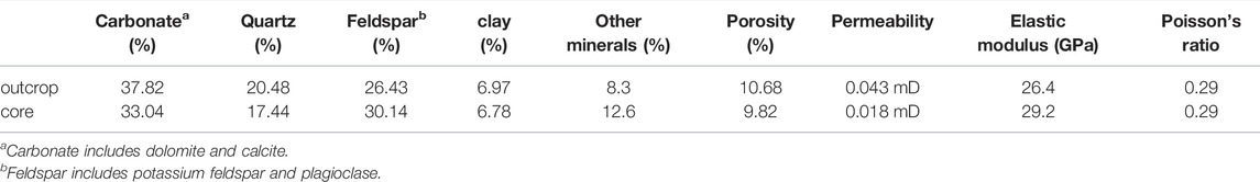
TABLE 1. Property comparison of cores and outcrop.
After the weathered surfaces were removed, the outcrops were cut into 300 × 300 × 300 mm3 cubes with a CNC sandline cutting machine. To simulate the horizontal bedding planes of the reservoir, one surface of the cubes needs to parallel to the bedding planes. Then a borehole parallel to the bedding planes with a length and diameter of 165 and 16 mm, respectively, was drilled in the center of the cube to simulate a horizontal well. After that a 150 mm steel cylinder is placed and cemented into the wellbore with high-strength epoxy resin, leaving a 15 mm long open hole section. The final processed and schematic specimen are shown in Figure 2A. Generally, we mark the surface where the wellbore is located as S1, and the opposite surface is S6, which will be perpendicular to the minimum horizontal principal stress. And the two planes parallel to the bedding are marked as S2 and S5 planes respectively, and the remaining two planes are marked as S3 and S4 planes, as shown in Figure 2B. In this study, to simulate horizontal well fracturing, the vertical stress is applied perpendicular to the bedding planes, and the minimum horizontal principal stress is applied along the wellbore.
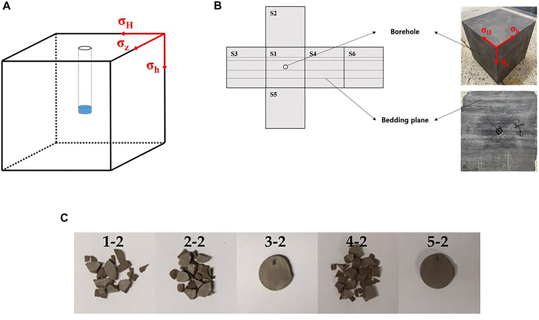
FIGURE 2. The specimens for fracturing experiments and soaking experiments. (A) Sketch of the thin interbedded specimen; (B) Display of thin interbedding and six surfaces (C) The specimens for soaking experiments.
The cores of Permian Lucaogou formation in Jimsar Sag, Junggar Basin, China were selected for CO2 soaking study. Total of 12 specimens were selected from six adjacent cores obtained from the same batch and cut into thin slices with a diameter of 2.5 cm and a thickness of 1 cm. The corresponding relationship between a core number and specimen number is shown in Table 2. Among them, specimen 6# and 7# were used to study the changes of micro pore structure after CO2-water-rock interaction through SEM experiments, and the other 10 specimens were used to study the influence on mineral composition through the XRD experiment. Due to the SEM experiment will not damage the specimen, the changes of pore structure before and after soaking in the same specimen or even in the same position can be directly compared. On the contrary, each XRD experiment will cause irreversible damage to the specimen and make it impossible to reuse. Therefore, specimens 1-1#, 2-1#, 3-1#, 4-1#, and 5-1# were directly used for testing the original mineral composition, while specimens 1-2#, 2-2#, 3-2#, 4-2#, and 5-2# were used for testing the mineral composition after soaking. According to the experimental scheme described below, specimens 1-2, 2-2, and 4-2 need to be broken into fragments before soaking, as shown in Figure 2C.
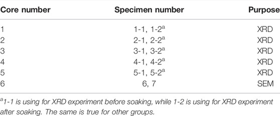
TABLE 2. The corresponding relationship between core number and specimen number.
Before the soaking experiment, according to the crude oil properties of the Jimsar reservoir, carbon tetrachloride and ethanol were mixed 1:1 to form an oil washing agent used to pretreat specimens. The whole pretreatment lasted for 30 days to ensure that all crude oil in the specimens was cleaned out.
Experimental Scheme
According to field data from the Jimsar reservoir (Chen C et al., 2021; Cheng, 2021; Zhang, 2021), the horizontal stress difference ranges from 4 to 12 MPa but is mainly close to 8 MPa. Hence, the horizontal stress difference was set as 4, 8, and 12 MPa respectively in accordance with the practical designs of the Jimsar reservoir during the fracturing experiments. At the same time, considering that horizontal well was widely employed in Jimsar reservoirs, the minimum horizontal principal stress was applied along the wellbore, while the vertical stress was applied perpendicular to the bedding planes, for the purposes of simulating horizontal well fracturing. The vertical stress is generally set at 20 MPa, but 30 MPa is used in the comparative experiment to study the initiation and propagation behavior of fractures under high vertical stress. During specimen processing, natural fractures in two specimens are retained, which will be used to study the effect of natural fractures on CO2 fracturing. In addition, to study the influence of fluid type on the characteristics of fractures, water, liquid CO2, and supercritical CO2 were used for fracturing experiments in specimens without nature fractures. The experimental schemes were designed as shown in Table 3. In order to reduce the influence of accidental factors, two specimens were prepared for each experimental scheme. And taking the experimental scheme of specimen 5# and 6# as the standard, other experiments only change one experimental condition, so as to form a contrast.

TABLE 3. The experimental schemes of fracturing experiment.
For soaking experiments, the temperature of 90°C and pressure of 40 MPa were realized in a reactor to simulate the CO2–water–rock interaction during the shut-in period of CO2 pre-pad energized fracturing operation in Jimsar reservoirs. And three factors, namely specimen specification, soaking medium, and reaction time, which can affect the CO2–water–rock interaction, were investigated in detail. The experimental schemes were designed as shown in Table 4.

TABLE 4. Scheme of soaking experiment.
Experimental Procedure
True Triaxial Fracturing Experiment
Unlike water-based fluids, the physical properties of CO2-based fluids, especially those of supercritical CO2, were temperature-sensitive. CO2 keeps liquid at a low temperature and transforms supercritical when the critical temperature and critical pressure are simultaneously exceeded. Thus, the temperatures of both the supercritical CO2 and the specimen need to be strictly controlled during supercritical CO2 fracturing experiments. The experimental procedures are as follows:
Preparation of CO2 and Preheating of Specimen
Before the fracturing experiment, CO2 needs to be transformed into the target phase. In case of liquid CO2 fracturing, the CO2 in the gas cylinder needs to be released into the cooling unit to cool down to −4°C, then pumped into the intermediate vessel and pressurized to 8 MPa. If supercritical CO2 was needed, on the previous basis, the intermediate vessel should be heated to 90°C by a heating jacket for at least 8 h to ensure that the CO2 is fully transformed into a supercritical state. On the other hand, the specimen also needs to be preheated before supercritical CO2 fracturing. However, due to the large size of the specimen, it cannot be carried out directly on the cubic specimen chamber. The specimen will be preheated to 90°C through the incubator and maintained for 8 h. After taking out the specimen, it should be placed on the cubic specimen chamber as soon as possible to prepare for fracturing.
Specimen Fixing
The specimen was placed in the cubic specimen chamber with the borehole oriented horizontally in the x-direction and the bedding planes oriented perpendicular to the z-direction (Figure 1).
Stress Loading
Firstly, the triaxial stresses were all preloaded to 3 MPa by the hydraulic pump. Then, the vertical stress, the minimum horizontal principal stress, and the maximum horizontal principal stress were loaded to the target value in turn.
Fracturing
Fracturing fluids were injected into the bottom hole at the target injection rate by a syringe pump. And the wellhead pressure will be monitored in real-time and transmitted to the control software during the whole process. When the continuously rising pressure drops suddenly, accompanied by a dull sound from the specimen, it means that the specimen was broken down. If the subsequent pressure remains stable, it means that fractures have extended to the surface of the specimen, which is a sign of the end of the experiment. It is worth mentioning that, at this time, the specimen will emit a violent sound of gas leakage, which is caused by the instantaneous vaporization of liquid or supercritical CO2 after contact with the atmosphere.
Fracture Protruding
Since the fractures opened by CO2 are too thin to distinguish, water mixed with yellow dye was injected into the specimen with a low pump rate (10 ml/min) after fracturing. After the water flows out along the fractures, it leaves traces on the surface of the specimen, so that the fracture becomes eye-catching.
Analysis After Fracturing
Based on the analysis of the fracturing curve (wellhead pressure versus time) and fracture morphology on the specimen, we introduced CT scanning technology to clarify the propagation of fractures in the specimen. Then the specimen was dissected to determine the internal connection of the fractures.
Soaking Experiments
The principle of the soaking experiment is to place the specimen in a reactor filled with CO2 solution and simulate the continuous contact process between CO2, water, and reservoir rocks during well soaking through external heating and pressurization. The experimental procedures are as follows:
Confirmation of Initial Mineral Composition and Microstructure
After 30 days of pretreatment, we believe that there is no crude oil in the specimen. According to the experimental scheme, SEM or XRD experiments were conducted on the specimens before soaking to obtain the original pore structure information and initial mineral composition.
Preparation of CO2 and Preheating of Specimen
Put the specimen into the reactor and add 100 ml water. After placing the fluororubber ring, installed the reactor and fastened it with screws. Then the reactor was preheated to 90°C using an incubator for 8 h. During specimen preheating, CO2 also needed to be pressurized to 40 MPa in the intermediate vessel and preheated to 90°C. The specific method is completely consistent with the operation in the fracturing experiment.
Injection of CO2 and Soaking
After preheating, opened the valve between the intermediate vessel and the reactor to connect them, which led to the release of CO2 into the reactor. It should be noted that once connected, the pressure in the intermediate vessel will decrease significantly and finally reach equilibrium with the pressure in the reactor. Therefore, it is necessary to continue to operate the syringe, and finally, make the pressure reach 40 MPa again. After that, disconnected all valves to turn the reactor into an independent system. And still placed the reactor in the incubator until the target time.
Confirmation of Final Mineral Composition and Microstructure
When reaching the target time, the reactor was taken out. Slowly open the vent valve on the reactor to release CO2 into the atmosphere. Then opened the reactor and took out the specimen. After drying the specimen, the SEM or XRD experiment was conducted again to obtain the pore structure information and mineral composition after dissolution. Notably, based on the advanced positioning technology, two SEM experiments can observe the pore structure at the same point. Therefore, the dissolution degree can be judged by directly comparing the changes of pore structure before and after soaking at the target position.
Results and Discussion of CO2 Fracturing Experiment
Notably, except for specimen 1# and specimen 2# fractured by water, similar results were obtained from the two experiments conducted under identical conditions. Therefore, eight representative experiments under different conditions were selected for analysis in this section.
Pressure Curve
The pressure curve records the fluctuation of bottom hole pressure (BHP) with time. And compared with the hydraulic fracturing for other types of specimens, there are two significant differences in the pressure curve of CO2 fracturing applied in thin interbedded shale. As shown in Figure 3. The first difference is the initial pressure. In hydraulic fracturing experiment, the pressure always rises from zero, while in CO2 fracturing, whether in liquid or supercritical state, the initial pressure is 8MPa, that is, the pressure of CO2 in the intermediate vessel. And another difference is that there are two kinds of pressure curves among all experiments, corresponding to two different fracture processes. In the first case, similar to the conventional hydraulic fracturing, the CO2 fracturing fluid silt in the bottom hole, which causes the BHP to rise gradually until it reaches the highest point, namely breakdown pressure, and then the pressure drops instantly after the specimen breaking. In this case, the breakdown point can be clearly observed on the curve (Figure 3A). The second case is that the break occurs immediately after the injection of CO2 accompanied by an obvious sound of gas release, and the pressure maintains near the initial pressure in the subsequent injection process, without a distinct breakdown point observed (Figure 3B).
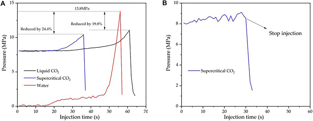
FIGURE 3. The pressure curves: (A) Pressure cruves with an obvious breakdown point of water, liquid CO2 and supercritical CO2; (B) Pressure cruve without breakdown point.
Breakdown Pressure
In this study, three different fracturing fluids, namely water, liquid CO2, and supercritical CO2 were used to fracture the Jimsar thin interbedded shale specimens respectively. The maximum breakdown pressure (13.8 MPa) appears on specimen 2#, which own to the highest friction and the least filtration effect of water. While for specimen 1#, which was also fractured by water, the breakdown pressure shown in the pressure curve is much lower than that of specimen 2#, because it only opened one bedding plane. Moreover, the breakdown pressure of other specimens fractured by liquid or supercritical CO2 is also significantly smaller. Compared with specimen 2#, it decreased by 19.8% in specimen 3# and 24.4% in specimen 5# respectively, as shown in Figure 3A. This phenomenon is attributed to the fact that ultra-low viscosity and high diffusivity can make CO2 enter the pores more easily, to increase the pore pressure and reduce the effective normal stress, and finally lead to the opening of fractures at lower pressure (Zhang et al., 2016; Wang et al., 2018). Based on the statistic, it can be inferred that if a water-based fracturing fluid with higher viscosity is used, the corresponding breakdown pressure will be greater. Therefore, CO2 can fracture thin interbedded shale at lower breakdown pressures than water-based fracturing fluid, which is a major advantage of CO2 fracturing. Similar conclusions were also summarized by other experiments and numerical simulations (Kizaki et al., 2012; Chen et al., 2015; Zhang et al., 2017; Liu et al., 2018).
Fracture Morphology
Compared with the fractures opened by fracturing operation in the formation, the fractures opened by fracturing experiment in the laboratory are thinner in width, especially by CO2 fracturing. The fractures on the surface of the specimen are even difficult to distinguish with the naked eye. Therefore, in order to clearly observe the fracture morphology, the water mixed with dye was injected into the specimen at a low speed after fracturing, so as to outline the fracture trace on the specimen surface. The effects of different experimental conditions on fracture morphology were analyzed. At the same time, CT scanning was introduced to observe the extension of fractures inside the specimen. Based on these two methods, the impacts of fracturing fluid type, vertical principal stress, horizontal principal stress difference and natural fractures on fracture characteristics were discussed.
Impact of Fracturing Fluid
Figure 4 show the fracture morphology induced by water on specimen 1#, liquid CO2 on specimen 3# and supercritical CO2 on specimen 5#, respectively. It can be seen intuitively from the figure that only one horizontal bedding plane is opened on specimen 1#, while a complex fracture network including two horizontal bedding planes and a longitudinal fracture appears on specimen 3# and specimen 5# by direct observation.
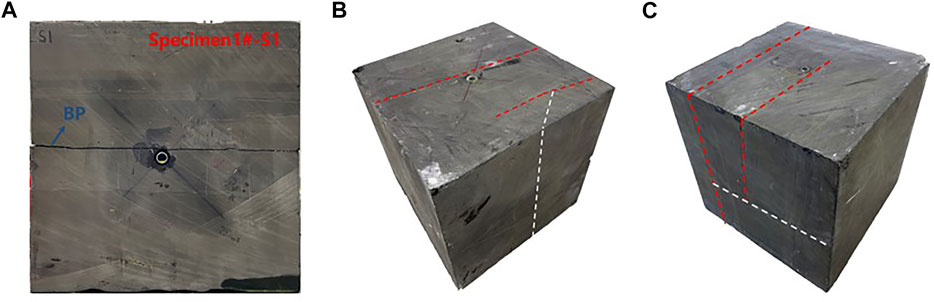
FIGURE 4. Fracture morphology created by water, liquid CO2, and supercritical CO2 respectively: (A) A completely propagated bedding plane created by water on specimen 1#; (B) Three fractures created by liquid CO2 on specimen 3#; (C) Three fractures created by created by liquid CO2 on specimen 5#.
There is another difference between the three specimens. The fracture created by water penetrates through the entire specimen, which means that the fracture is completely opened. Nevertheless, the fracture created by liquid or supercritical CO2 is propagated incompletely. Neither bedding nor longitudinal fracture appearing on one surface can be observed on the opposite surface. Therefore, to find out the distribution of fractures in the specimen, we scanned specimen 3# and 5# respectively and obtained an internal section containing fractures of the specimen. The schematic diagram of the scanning position and actual scanning results are shown in Figure 5. In the schematic diagram (Figures 5A,D), the black dotted line indicates the fractures that can be directly observed from the specimen surface, and the blue and orange rectangles indicate the scanned position. In the scanning task of two specimens, scanning section 1 that is passing through the wellbore passes vertically through two bedding planes. From this section, the starting and ending positions of the two bedding planes extending along the wellbore direction and the potential communication relationship between them can be revealed. And scanning section 2 is located between and parallel to two bedding planes. From this section, the extension degree of longitudinal fracture can be reflected. Since the scanning section 2 does not contain the wellbore, the relative position of the wellbore is indicated by a black dotted line in the scanning diagram.
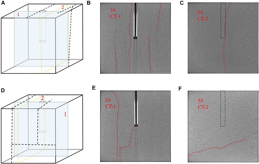
FIGURE 5. CT scanning images of the specimens 3#: (A) Scanning position of specimen 3#; (B) Scanning section 1 of specimen 3#; (C) Scanning section 2 of specimen 3#; (D) Scanning position of specimen 5#; (E) Scanning section 1 of specimen 5#; (F) Scanning section 2 of specimen 5#.
As can be seen from the CT scan results (Figure 5), no matter specimen 3# or 5#, there are more than two actually activated bedding planes in the cube as shown on the surface. With the help of longitudinal fractures, they connect with each other to build a fracture network. It is noteworthy that most bedding planes are not completely open. As shown in Figure 5B, four bedding planes are activated in the specimen, but only one of them runs through the whole specimen, while the other three extend to the rock surface only along one side of the longitudinal fracture. This phenomenon means that although CO2 has a strong rock-breaking capacity, its fracture expansion ability is weak. Another difference between the two specimens is the sequence of fracture initiation. In specimen 3#, a longitudinal fracture is directly connected with the wellbore (Figure 5C). The longitudinal fracture started to breakdown first and activates the bedding plane after met it during propagation. While in specimen 5#, a bedding plane just passes through the wellbore, so it was activated directly in the open hole section (Figure 5E). From this feature, it can be inferred that the bedding plane has an advantage in the competition of fracture initiation. This can be attributed to the weak cementation strength of the bedding plane, the strong penetration of CO2, and the vibration damage to the bedding plane during drilling, which may even open the bedding plane to a certain extent in advance.
In addition, the width of the fracture caused by water and CO2 is obviously different. Although the number and complexity of fractures on specimens 3# and 5# are more, the fracture width of them is smaller than specimen 1#. On the surface of specimens 3# and 5#, the fractures are so thin that it is difficult to be directly identified. While on the surface of specimen 1#, the fracture is quite obvious.
Based on the results, it can be concluded that compared to hydraulic fracturing, CO2 fracturing can form a more complex fracture morphology, which is beneficial for production, but CO2 has less capability to propagate the fracture. It is necessary to inject high viscosity fracturing fluid to enhance the fracture length. And the narrow fracture width formed by CO2 necessitates a smaller proppant.
Impact of Horizontal Principal Stress Difference
In the current understanding of hydraulic fracturing operation of conventional reservoirs, a complex fracture network is more likely to be formed under low horizontal stress difference. However, this conclusion seems not to be able to extend to the CO2 fracturing of Jimsar shale. In this study, three horizontal stress difference of 4, 8 and 12 MPa were simulated for three specimens, and the fractures morphology are shown in Figures 6A–C. From experimental results, it can be counted that two horizontal bedding planes and one vertical fracture are opened in the three specimens, which indicates that there is no apparent difference in fracture complexity under low, medium, and high horizontal stress differences.
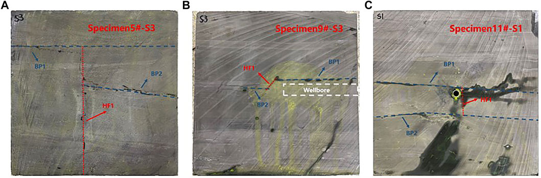
FIGURE 6. Fracture morphology created by supercritical CO2 under different horizontal principal stress difference: (A) Specimen 5#; (B) Specimen 9#; (C) Specimen 11#.
This phenomenon can also be attributed to the ultra-low viscosity of CO2 and the weak bonding strength of the horizontal bedding planes. Compared with water-based fracturing fluid, the ultra-low viscosity of CO2 brings stronger penetration ability, which makes it more easily enter the bedding planes and further weaken its bonding strength, so as to open the bedding regardless of horizontal principal stress difference. Based on this phenomenon, we can infer that for Jimsar thin interbedded shale reservoir, there is no obvious advantage of forming a complex fracture network under low horizontal stress difference.
Impact of Vertical Principal Stress
From the discussion of fracturing fluid type and horizontal principal stress difference, it can be inferred that there is competition in the process of fracture opening in different directions, and the horizontal bedding planes always occupy the advantage. Considering that this experiment simulates horizontal well fracturing and the wellbore direction is parallel to the bedding plane, the stress perpendicular to the bedding plane, that is, the vertical stress, will also play a vital role in the opening of the bedding plane. As shown in Figure 7A. When the vertical stress increased to 30 MPa, one bedding plane and two longitudinal fractures can be observed from the surface of the fractured specimen 7#. Two longitudinal fractures are also incomplete fractures, which only propagated to S3 and S4 planes respectively, rather than the whole specimen. In fact, there is another possibility that the two fractures on S3 and S4 are actually the same fracture, which tilts or bends inside the sample, resulting in different heights after propagating to the two surfaces. In order to determine the actual morphology of the longitudinal fractures and whether other potential branch fractures exist, specimen 7# was scanned by CT. The schematic diagram of the scanning position and actual scanning results are shown in Figures 7B,C. Same as specimen 3# and 5#, two sections passing through the wellbore were selected for scanning, and their positions were marked with blue and orange rectangular boxes respectively. Section 1 is perpendicular to the bedding plane to observe the propagation of the fractures. In this section, three independent fractures can be clearly distinguished. According to the spatial relationship, the two transverse fractures in the CT scan images represent the longitudinal fractures in the cube specimen, while the vertical fracture is the bedding plane. Compared with CT images of specimen 3# and 5#, there are significantly fewer bedding planes opened in specimen 7#, which means that the larger vertical stress has an inhibitory effect on the opening of the bedding plane and promotes the opening of longitudinal fractures to a certain extent. Section 2 is parallel to the bedding plane, and the morphology of longitudinal fractures is shown on it. Obviously, the two longitudinal fractures are also incomplete propagation.
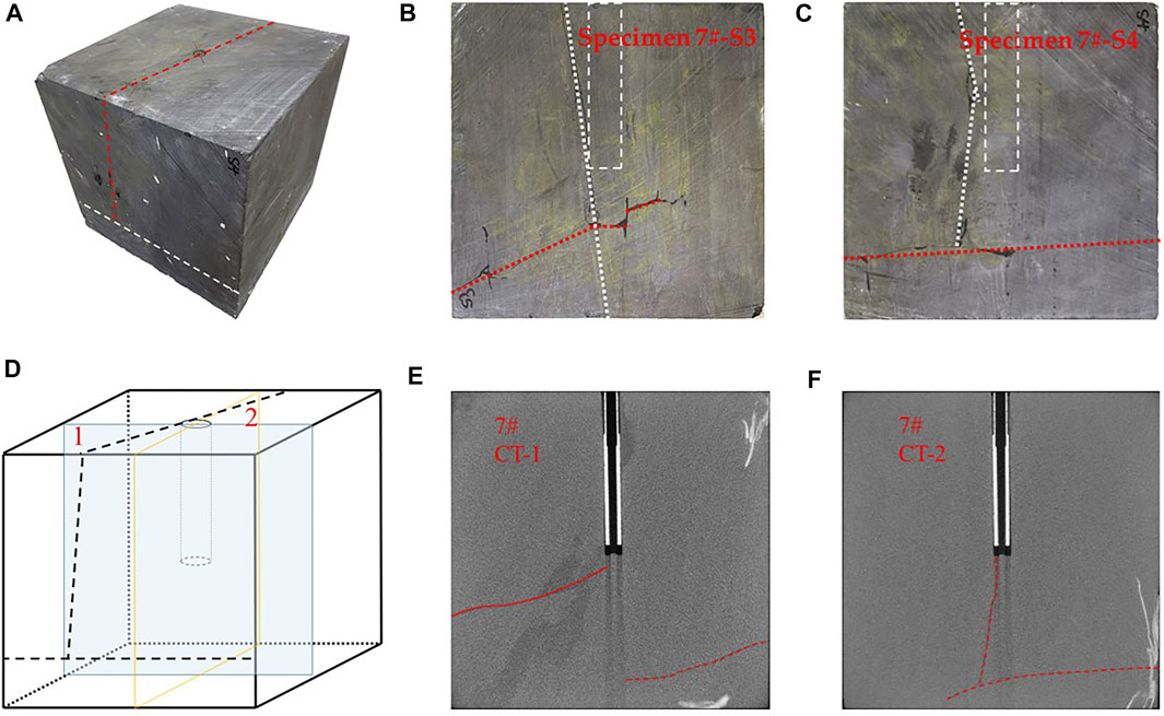
FIGURE 7. Fracture morphology created by supercritical CO2 under high vertical stress: (A) Fracture morphology of specimen 7#; (B) S3 surface of specimen 7#; (C) S4 surface of specimen 7#; (D) Scanning position of specimen 7#; (E) Scanning section 1 of specimen 7#; (F) Scanning section 2 of specimen 7#.
Impact of Natural Fractures
By comparing specimen 13# and specimen 3#, it can be found that the fracture morphology of specimens with different natural fractures is quite different. It can be seen intuitively that specimen 13# (Figure 8A) has complex fracture morphology. On this specimen, there are three kinds of fractures namely horizontal bedding planes, natural fractures, and longitudinal fractures. After the supercritical CO2 is injected into the specimen, longitudinal fracture starts along the direction of maximum horizontal principal stress at the bottom of the well. Then the bedding planes and natural fractures closest to the wellbore are connected to the new longitudinal fracture so that the pressure can spread in and open them. According to the statistical, there are four horizontal bedding planes, five natural fractures, and three longitudinal fractures that can be observed.
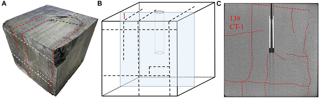
FIGURE 8. Fracture morphology created by supercritical CO2 on a specimen with nature fractures: (A) Fracture morphology of specimen 13#; (B) Scanning position of specimen 13#; (C) Scanning image of specimen 13#.
The section of CT scanning that is parallel to the wellbore but perpendicular to the bedding plane was applied to specimen 13#, which can be used to observe the distribution of the fractures in the specimen (Figure 8B). As shown in Figure 8C, specimen 13# with natural fractures has the largest number and the most complex distribution of fractures. Obviously, the natural fractures were activated when connected to extending bedding planes and longitudinal fractures. Moreover, the activated natural fractures continue to expand, which is also conducive to linking the distal bedding planes. And finally, the three types of fractures constructed a complex fracture morphology together. So there is no doubt that the development degree of natural fractures is the most important factor affecting the complexity of fractures.
Results and Discussion of Soaking Experiment
Variation of Mineral Composition
According to the experimental scheme, XRD experiments were conducted on the specimens before and after soaking experiments to obtain the initial mineral composition and the mineral composition after dissolution. The results are shown in Table 5.
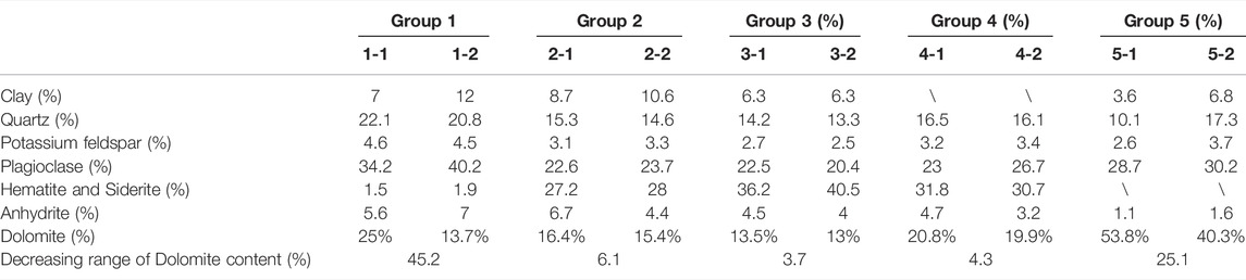
TABLE 5. Changes of mineral composition of Jimsar before and after soaking.
Through comparison, it can be judged that the initial mineral types of the five groups of specimens are roughly the same, but the distribution is different, showing a certain heterogeneity. On the whole, Jimsar reservoir contains fewer clay minerals, with an average of only 5.12%; Other components include quartz of about 16%, feldspar (potassium feldspar and plagioclase) of about 30%, dolomite of about 25%, hematite and siderite of about 20%. After soaking, the most significant change is that the content of dolomite decreases evidently, and the percentage content of other minerals increases accordingly. From this phenomenon, it can be deduced the main dissolved mineral in the interaction between CO2, water, and rock during soaking is dolomite. In order to clarify the influence of different factors on CO2-water-rock interaction, the dolomite content of five groups of specimens was extracted and further analyzed separately, as shown in the last row of Table 5.
Combined with the experimental scheme in Table 4, the experimental results of five groups of specimens are discussed as follow, which can provide guidance for on-site construction.
In groups 1 and 2, the fragment specimens were soaked with CO2 solution for 5 and 2 days respectively. It can be seen from Table 5 that the dolomite decreased by 45.2% after 5 days, much higher than 6.1% after 2 days, indicating that prolonging the soaking time is conducive to the dissolution of dolomite. Group 5 is to soak the intact rock slice with CO2 solution for 5 days, and the final dolomite reduced by 25.1%, which indicates that even if the contact area between CO2 and rock is small, CO2 solution can invade the rock for dissolution under long-time soaking, so as to obtain excellent dissolution effect. This means that prolonging the soak time during on-site construction, that is, increasing the interaction time of CO2-water-rock, is an effective method to strengthen the dissolution.
In group 2 and 3, the intact rock slice specimen and fragment specimen were soaked with CO2 solution for 2 days. After soaking, the dolomite content in the two groups of specimens decreased by 6.1 and 3.7% respectively, which indicates that compared with the intact rock slice, fragments have a larger contact surface with CO2 solution, which is conducive to dolomite dissolution. The same conclusion can be obtained by comparing the experiments of group 1 and group 5. After soaking intact rock slices and fragments with CO2 solution for 5 days, the dolomite content decreased by 45.2 and 25.1% respectively. At the same time, it can be found that the dissolution difference caused by rock fragmentation will further increase with the extension of soaking time. This result shows that the construction of a complex fracture network in CO2 pre-pad energized fracturing operation can not only obtain more oil and gas channels but also be of great significance for dissolving carbonate minerals, both of which will contribute to improving production.
In groups 2 and 4, CO2 solution and pure CO2 (supercritical state) were used to soak fragment specimens for 2 days respectively The experimental results show that the content of dolomite decreased by 6.1% after soaking with CO2 solution, which is higher than 4.3% after soaking with pure CO2, indicating that CO2 solution has better dissolution ability than pure CO2. This means that in CO2 pre-pad energized fracturing operation, the combined fracturing method of CO2 + water (or other water-based fracturing fluid) has more advantages in enhancing dolomite dissolution than conventional CO2 fracturing.
Variation of Pore Structure
According to the experimental scheme, the pore structure before and after soaking at the target position was acquired after two SEM experiments and one soaking experiment. Evidently, compared with pure CO2, the CO2 solution has a stronger corrosion ability.
Soaking the Specimen With CO2 Solution
As shown in Figures 9A,B, the micro surface morphology of specimen No.6# obtained by two SEM experiments changed significantly. The five positions marked by the red frame are the most remarkable. Under the condition of formation temperature and pressure, after soaking the specimen with CO2 solution for 7 days, these positions became rough, and the originally covered rocks were dissolved to expose the pores in the lower part. From the previous XRD experiments, it can be inferred that these dissolved rocks are dolomite. And this can also be confirmed by energy dispersive spectrum (EDS) analysis technology. In the first SEM experiment, several targets were selected for EDS analysis. After soaking, some targets remained as they were, while others were dissolved. EDS results (Figures 9C,D) shows that the main elements of the dissolved rock include Ca, Fe, C, O, and Mg, indicating that the mineral is dolomite (ferrodolomite). The almost unchanged rock include C, O, Na, Al, and Si, indicating that the mineral is feldspar. And in order to observe the change of pore structure more intuitively, we specially marked two positions (Ⅰ and Ⅱ) and further enlarged them, as shown in Figures 9E–H.
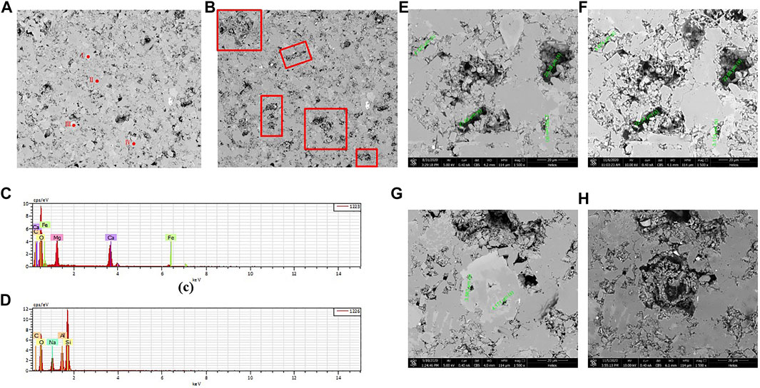
FIGURE 9. The pore structure before and after soaking with CO2 solution and EDS analysis results: (A) The pore structure before soaking; (B) The pore structure after soaking; (C) EDS analysis results of Position Ⅰ; (D) EDS analysis results of Position Ⅱ. (E) Position Ⅲ before dissolution; (F) Position Ⅲ after dissolution; (G) Position Ⅳ before dissolution; (H) Position Ⅳ after dissolution.
There are two kinds of surface changes after soaking in CO2 solution. The first case is that the original pore size is slightly affected because the main mineral around the pore is insoluble, as shown in Figures 9E,F. The dimensions of the four pores in the field of view were calibrated, which were 4.322, 21.65, 22.38 and 2.780 μm before soaking and 4.874, 22.14, 22.66 and 3.119 μm after soaking. Increased by 12.77, 2.26, 1.25 and 12.19% respectively. In the second case, as shown in Figures 9G,H, after soaking, the original mineral is dissolved and emptied to form new pores. Therefore, expanding the original pores, forming new pores, or even causing communication between pores, is the main mechanism of CO2 solution soaking rock to improve porosity and permeability.
Soaking the Specimen With Pure CO2
After soaking with pure CO2 for 7 days at the same temperature and pressure, the original pore structure of specimen No.7# was hardly affected and few new pores were formed, as shown in Figures 10A,B. Similarly, we magnify it to observe the change of pore structure, as shown in Figures 10C,D.

FIGURE 10. The pore structure before and after soaking with pure CO2: (A) Before soaking; (B) After soaking; (C) Enlarged view of a typical position before soaking; (D) Enlarged view of a typical position after soaking.
This is an area with complex pore distribution. After measurement, the dimensions of the three pores before soaking are 10.12, 11.40 and 3.877 μm respectively. And it expanded to 10.70, 11.70 and 3.951 μm after soaking. The increase was only 5.7, 2.63, and 1.91% respectively. Compared with the previous dissolution results of CO2 solution, the dissolution effect of pure CO2 on rock Jimsar is weaker.
Conclusions
This study aims to explore the unique advantages of carbon dioxide on thin interbedded shale in CO2 pre-pad energized fracturing operation, including early rock breaking stage and later CO2-water-rock interaction. The characteristics of fractures created by CO2 fracturing fluids, the dissolution law of minerals, and the change of pore structure were investigated via a series of fracturing experiments and soaking experiments combined with CT, XRD, and SEM experiments. The findings are summarized as follows:
1) By analyzing pressure curves, it can be found that the fracture pressure of liquid CO2 and supercritical CO2 is significantly lower than that of water-based fracturing fluid, by 19.8 and 24.4%, respectively.
2) For thin interbedded rocks, either water or CO2 is used as fracturing fluid, the bedding planes are easily opened during fracturing. However, in this study, longitudinal fractures can be induced by CO2 and intersect the bedding planes to build a fracture network. However, by analyzing the distribution of fractures on the different surfaces of the specimen, it can be found that most fractures can only extend along one side of the wellbore to the rock surface or extend for a short distance, which indicates that although CO2 has a strong rock-breaking ability, its fracture expansion ability is weak.
3) Due to the ultra-low viscosity and strong penetration ability of liquid/supercritical CO2 and the weak bonding strength of the bedding planes, bedding planes are still the easiest to be opened compared with fractures in other directions even under low horizontal stress difference. Therefore, compared with other conventional reservoirs, the horizontal stress difference is not a crucial factor affecting the fracture complexity in Jimsar thin interbedded reservoir. However, the larger vertical stress has an inhibitory effect on the opening of bedding planes and a facilitating effect on the opening of the longitudinal fractures, which facilitates the construction of complex fracture networks.
4) In this study, the specimen with natural fractures has the largest number and the most complex distribution of fractures. Natural fractures can be activated simultaneously with bedding planes, which will induce a complex fracture network. By contrast, if there are few natural fractures, the opened bedding planes usually expand directly to the specimen surface, and CO2 diffuses into the atmosphere along the fracture, resulting in the subsequent failure to hold up high pressure and form new fractures.
5) Compared with pure CO2, the CO2 solution has better dissolution capacity, and the main dissolved minerals is carbonate. For fragmentary specimens, the dissolution ratio of carbonate reached 6.1% after 2 days of soaking in CO2 solution at formation temperature and pressure (90°C, 40 MPa) and 45.2% after 5 days, which is 20.1% higher than that of lamellar specimens. After the dissolution of carbonate, original pores were enlarged or new pores were exposed, causing more pore connectivity relationships.
6) For the CO2 pre-pad energized fracturing operation of Jimsar shale reservoir, constructing a complex fracture network can not only expand the range of the oil seepage channel but also increase the contact area between CO2 solution and rock. Prolonging the soaking time can increase the interaction time between CO2 solution and rock. After CO2 fracturing the formation, continued injection of water-based fracturing fluid can prolong the fractures and enhance the dissolution of carbonate. These are all effective means to increase production.
Data Availability Statement
The raw data supporting the conclusions of this article will be made available by the authors, without undue reservation.
Author Contributions
Conceptualization, BL and JM; Investigation, BL and SZ; Data curation, BL, JM, and XM; Writing—original draft prepara-tion, BL and XM; Writing—review and editing, BL and FW. All authors have read and agreed to the published version of the manuscript.
Funding
This paper is supported by Project of Research and application of key technologies for exploration and development of conti-nental medium and high maturity shale oil (Grant No. 2019E-26).
Conflict of Interest
The reviewer LT declared a shared affiliation, with no collaboration, with the authors to the handling editor at the time of the review.
The authors declare that the research was conducted in the absence of any commercial or financial relationships that could be construed as a potential conflict of interest.
Publisher’s Note
All claims expressed in this article are solely those of the authors and do not necessarily represent those of their affiliated organizations, or those of the publisher, the editors and the reviewers. Any product that may be evaluated in this article, or claim that may be made by its manufacturer, is not guaranteed or endorsed by the publisher.
References
Ahmed, M. G., Qi, Q., Russell, M., Scott, N., and Ted, R. (2014). “New Insights into Hydraulic Fracturing of Shale Formations,” in International Petroleum Technology Conference, Doha, Qatar, 20-22 January 2014, SPE17594. 0.2523/17594-MS.
Arif, M., Zhang, Y., and Iglauer, S. (2021). Shale Wettability: Data Sets, Challenges, and Outlook. Energy Fuels 35, 2965–2980. doi:10.1021/acs.energyfuels.0c04120
Bennour, Z., Ishida, T., Nagaya, Y., Chen, Y., Nara, Y., Chen, Q., et al. (2015). Crack Extension in Hydraulic Fracturing of Shale Cores Using Viscous Oil, Water, and Liquid Carbon Dioxide. Rock Mech. Rock Eng. 48 (4), 1463–1473. doi:10.1007/s00603-015-0774-2
Chen, C., Wang, B., Wang, J., Xu, Y., Qin, Y., and Li, X. (2021). Fracturing Technologies for Horizontal Wells in the Second-Class Shale Oil Reservoirs of the Lower Sweet Spot Areas in Jimusar. Pet. Dill. Tec. 49 (04), 112–117. doi:10.11911/syztjs.2021089
Chen, Y., Nagaya, Y., and Ishida, T. (2015). Observations of Fractures Induced by Hydraulic Fracturing in Anisotropic Granite. Rock Mech. Rock Eng. 48 (4), 1455–1461. doi:10.1007/s00603-015-0727-9
Chen, Z., Liu, H. L., Li, Y. J., Shen, Z. Q., and Xu, G. Q. (2021). The Current Status and Development Suggestions for Shale Oil Reservoir Stimulation at Home and Abroad. Pet. Dill. Tec. 49 (04), 1–7. doi:10.11911/syztjs.2021081
Cheng, L. M. (2021). Exploration of Geological Engineering Integrated 3D Fracturing Design for Horizontal wells in Jimsar Shale Oil Reservoirs. Pet. Geo. Eng. 35 (02), 88–92. doi:10.3969/j.issn.1673-8217.2021.02.018
Chuprakov, D. A., Akulich, A. V., Siebrits, E., and Thiercelin, M. (2010). Hydraulic Fracture Propagation in a Naturally Fractured Reservoir. SPE Prod. Oper. 26 (1), 88–97. doi:10.2118/128715-MS
Cipolla, C. L., Lolon, E. P., and Mayerhofer, M. J. (2009). Resolving Created, Propped, and Effective Hydraulic-Fracture Length. SPE Prod. Oper. 24 (04), 619–628. doi:10.2118/0309-0058-JPT10.2118/129618-pa
Curtis, J. B. (2002). Fractured Shale-Gas Systems. Bulletin 86 (11), 1921–1938. doi:10.1306/61EEDDBE-173E-11D7-8645000102C1865D
Du, Y., Sang, S., and Wang, W. (2018). Study and Review on Geochemical Effect of Coal and Rock Injected with Super-critical CO_2. Coal Sci. Tec. 46 (3), 10–18. doi:10.13199/j.cnki.cst.2018.03.002
Guo, C., Xu, J., Wei, M., and Jiang, R. (2015). Experimental Study and Numerical Simulation of Hydraulic Fracturing Tight sandstone Reservoirs. Fuel 159, 334–344. doi:10.1016/j.fuel.2015.06.057
Guo, Y., Hou, L., Yao, Y., Zuo, L., Wu, Z., and Wang, L. (2020). Experimental Study on Influencing Factors of Fracture Propagation in Fractured Carbonate Rocks. J. Struct. Geology. 131, 103955. doi:10.1016/j.jsg.2019.103955
Hou, B., Chen, M., Cheng, W., and Tan, P. (2014). Fracturing Mechanism of Shale Gas Reservoir with Variable Pump Rates. Chin. J. Geot. Eng. 36, 2149–2152. doi:10.11779/CJGE201411023
Hou, L., Zhang, S., Elsworth, D., Liu, H., Sun, B., and Geng, X. (2021). Review of Fundamental Studies of CO2 Fracturing: Fracture Propagation, Propping and Permeating. J. Pet. Sci. Eng. 205, 108823. doi:10.31224/osf.io/3tgps10.1016/j.petrol.2021.108823
Ishida, T., Chen, Y., Bennour, Z., Yamashita, H., Inui, S., Nagaya, Y., et al. (2016). Features of CO 2 Fracturing Deduced from Acoustic Emission and Microscopy in Laboratory Experiments. J. Geophys. Res. Solid Earth 121 (11), 8080–8098. doi:10.1002/2016JB013365
Jamison, W., and Azad, A. (2017). The Hydraulic Fracture - Natural Fracture Network Configuration in Shale Reservoirs: Geological Limiting Factors. J. Pet. Sci. Eng. 159, 205–229. doi:10.1016/j.petrol.2017.09.017
Jia, C. Z., Zheng, M., and Zhang, Y. F. (2012). Unconventional Hydrocarbon Resources in China and the prospect of Exploration and Development. Petrol. Explor. Dev. 39 (02), 129–136. doi:10.1016/s1876-3804(12)60026-3
Jiang, Z., Tang, X. L., Li, Z., Huang, H., Yang, P., Yang, X., et al. (2016). The Whole-Aperture Pore Structure Characteristics and its Effect on Gas Content of Longmaxi Formation Shale in the southeastern Sichuan basin. Earth Sci. Front. 23 (2), 126–134. doi:10.13745/j.esf.2016.02.013
King, G. E. (2010). “Thirty Years of Gas Shale Fracturing: what Have We Learned,” in SPE Annual Technical Conference And Exhibition, Florence, Italy, 19-22 September 2010, SPE133456. doi:10.2118/133456-MS
Kizaki, A., Tanaka, H., Sakaguchi, K., Sakaguchi, K., and Matsuki, K. (2013). Hydraulic Fracturing in Inada Granite and Ogino Tuff Using Super Critical Carbon Dioxide and Water as Fracturing Fluids. J. Mining Mater. Process. Inst. Jpn. 129, 461–466. doi:10.2473/journalofmmij.129.461
Lecampion, B., and Zia, H. (2019). Slickwater Hydraulic Fracture Propagation: Near-Tip and Radial Geometry Solutions. J. Fluid Mech. 880, 514–550. doi:10.1017/jfm.2019.716
Li, S., Zhang, S., Zou, Y., Ye, L., Ma, X. F., Ge, Q., et al. (2018). Experimental study on the features of hydraulic fracture created by slickwater, liquid carbon dioxide, and supercritical carbon dioxide in tight sandstone reservoirs, in The 52nd US Rock Mechanics Geomechanics Symposium held in Seattle, Washington, USA, 17–20 June 2018. ARMA 18, 767.
Li, S., Ma, X., Zhang, S., Zou, Y., Li, N., Zhang, Z., et al. (2019b). Experimental Investigation on the Influence of CO2-Brine-Rock Interaction on Tight Sandstone Properties and Fracture Propagation. Xinjiang Pet. Geology. 40 (3), 312–318. doi:10.7657/XJPG20190309
Li, S., Zhang, S., Ma, X., Zou, Y., Li, N., Chen, M., et al. (2019a). Hydraulic Fractures Induced by Water-/carbon Dioxide-Based Fluids in Tight Sandstones. Rock Mech. Rock Eng. 52 (9), 3323–3340. doi:10.1007/s00603-019-01777-w
Liu, G. Q. (2021). Challenges and Countermeasures of Log Evaluation in Unconventional Petroleum Exploratio. Petrol. Explor. Dev. 48 (05), 891–902. doi:10.1016/s1876-3804(21)60089-7
Liu, H., Kuang, L. C., and Li, G. X. (2020). Considerations and Suggestions on Optimizing Completion Methods of continental Shale Oil in china. Acta Petrol. Sin. 41 (04), 489–496. doi:10.7623/syxb202004011
Liu, L., Zhu, W., Wei, C., Elsworth, D., and Wang, J. (2018). Microcrack-based Geomechanical Modeling of Rock-Gas Interaction during Supercritical CO2 Fracturing. J. Pet. Sci. Eng. 164, 91–102. doi:10.1016/j.petrol.2018.01.049
Lyu, X., Zhang, S., Ma, X., Wang, F., and Mou, J. (2018). Numerical Study of Non-isothermal Flow and Wellbore Heat Transfer Characteristics in CO2 Fracturing. Energy 156, 555–568. doi:10.1016/j.energy.2018.05.126
Palisch, T. T. T., Vincent, M. C. C., and Handren, P. J. J. (2010). Slickwater Fracturing: Food for Thought. SPE Prod. Oper. 25 (03), 327–344. doi:10.2118/115766-PA
Ribeiro, L. H., Li, H., and Bryant, J. E. (2017). Use of a CO2-Hybrid Fracturing Design to Enhance Production from Unpropped-Fracture Networks. SPE Prod. Oper. 32 (01), 28–40. doi:10.2118/SPE-173380-MS10.2118/173380-pa
Song, Y., Li, Z., Jiang, Z. X., Luo, Q., Liu, D. D., and Gao, Z. Y. (2017). Progress and Development Trend of Unconventional Oil and Gas Geological Researc. Petrol. Explor. Dev. 44 (04), 638–648. doi:10.1016/s1876-3804(17)30077-0
Taheri Shakib, J., Akhgarian, E., and Ghaderi, A. (2015). The Effect of Hydraulic Fracture Characteristics on Production Rate in thermal EOR Methods. Fuel 141, 226–235. doi:10.1016/j.fuel.2014.10.063
Wang, J., Elsworth, D., Wu, Y., Liu, J., Zhu, W., and Liu, Y. (2018). The Influence of Fracturing Fluids on Fracturing Processes: A Comparison between Water, Oil and SC-CO2. Rock Mech. Rock Eng. 51, 299–313. doi:10.1007/s00603-017-1326-8
Xiao, N., Li, S., and Lin, M. Q. (2018). Effect of CO2-water-rock Interaction on Porosity, Permeability and Pore Structure Characters of Reservoir Rock: A Case Study of 35-3 Well in Yanchang Oilfield. Oilfield Chem. 2018 (1), 85–90. doi:10.19346/j.cnki.1000-4092.2018.01.016
Yang, Z., and Zou, C. N. (2019). Exploring Petroleum inside Source Kitchen”: Connotation and Prospects of Source Rock Oil and Gas. Petrol. Explor. Dev. 46 (01), 173–184. doi:10.1016/s1876-3804(19)30018-7
Yu, Z., Yang, S., Liu, L., Li, S., and Yang, Y. (2012). An Experimental Study on Water-Rock Interaction during Water Flooding in Formations Saturated with CO2. Acta Petrol. Sin. 33 (06), 1032–1042. doi:10.7623/syxb201206016
Yushi, Z., Xinfang, M., Tong, Z., Ning, L., Ming, C., Sihai, L., et al. (2017). Hydraulic Fracture Growth in a Layered Formation Based on Fracturing Experiments and Discrete Element Modeling. Rock Mech. Rock Eng. 50 (9), 2381–2395. doi:10.1007/s00603-017-1241-z
Zhang, J. (2021). Effective Development Practices of Geology-Engineering Integration on Unconventional Oil Reservoirs: Taking Lucaogou Formation Shale Oil in Jimsar Sag, Junggar Basin for Example. Fault-Block Oil & Gas Field 28 (02), 151–155. doi:10.6056/dkyqt202102002
Zhang, X., Lu, Y., Tang, J., Zhou, Z., and Liao, Y. (2017). Experimental Study on Fracture Initiation and Propagation in Shale Using Supercritical Carbon Dioxide Fracturing. Fuel 190, 370–378. doi:10.1016/j.fuel.2016.10.120
Zhang, X., Wang, J. G., Gao, F., and Ju, Y. (2017). Impact of Water, Nitrogen and CO 2 Fracturing Fluids on Fracturing Initiation Pressure and Flow Pattern in Anisotropic Shale Reservoirs. J. Nat. Gas Sci. Eng. 45, 291–306. doi:10.1016/j.jngse.2017.06.002
Zhou, X., and Burbey, T. J. (2014). Fluid Effect on Hydraulic Fracture Propagation Behavior: a Comparison between Water and Supercritical CO2-like Fluid. Geofluids 14 (2), 174–188. doi:10.1111/gfl.12061
Keywords: thin interbedded shale, carbon dioxide fracturing experiment, complex fracture morphology, CO2-water-rock interaction, mineral composition, pore structure
Citation: Li B, Mou J, Zhang S, Ma X, Zou Y and Wang F (2022) Experimental Study on the Interaction Between CO2 and Rock During CO2 Pre-pad Energized Fracturing Operation in Thin Interbedded Shale. Front. Energy Res. 10:825464. doi: 10.3389/fenrg.2022.825464
Received: 30 November 2021; Accepted: 08 April 2022;
Published: 25 April 2022.
Edited by:
Hui Pu, University of North Dakota, United StatesReviewed by:
Sen Wang, China University of Petroleum, Huadong, ChinaLeng Tian, China University of Petroleum, China
Zhifeng Luo, Southwest Petroleum University, China
Copyright © 2022 Li, Mou, Zhang, Ma, Zou and Wang. This is an open-access article distributed under the terms of the Creative Commons Attribution License (CC BY). The use, distribution or reproduction in other forums is permitted, provided the original author(s) and the copyright owner(s) are credited and that the original publication in this journal is cited, in accordance with accepted academic practice. No use, distribution or reproduction is permitted which does not comply with these terms.
*Correspondence: Jianye Mou, bW91amlhbnllQGN1cC5lZHUuY24=