 Ying Zhou1
 Jiyun Qin
95% of researchers rate our articles as excellent or good
Learn more about the work of our research integrity team to safeguard the quality of each article we publish.
Find out more
ORIGINAL RESEARCH article
Front. Energy Res. , 09 May 2022
Sec. Process and Energy Systems Engineering
Volume 10 - 2022 | https://doi.org/10.3389/fenrg.2022.824421
This article is part of the Research Topic Sustainable Planning and Life-Cycle Thinking of Energy Infrastructure View all 23 articles
Geothermal Aided Power Generation (GAPG) technology is a geothermal hybrid power system that geothermal energy has been integrated into the fossil fired plant to preheat the feedwater, and displace the extraction steam of fossil fired plant. In such a power system, the heat exchange process between extraction steam and geo-fluid occurs in a heat exchange between. When the geo-fluid in the heat exchanger quench to lower temperature for heat transfer purpose, silica scaling would occur in the heat exchanger system. The performance of the GAPG plant would be influenced by the configuration of the heat exchanger and silica scaling in the heat exchanger. For a GAPG plant, it has two possible configurations for a heat exchanger system: series arrangement and parallel arrangement. The different configuration also impacts on the technical performance of the GAPG plant. The silica scaling in the heat exchanger system would harm the performance of the GAPG plant. In this study, a GAPG power system from a 300 MW power plant is used as a case study to understand the impact of displacement selections and heat exchanger arrangement on the performance of the GAPG plant. It was found that there is no silica scaling occurring in heat exchangers system if geo-fluid is used to displace to high-grade extraction steam only. Furthermore, the Parallel arrangement is better than the Series arrangement in terms of the additional power output. Moreover, the GAPG plant has protentional to reduce carbon dioxide emissions by 13%.
With rapid economic development, the consumption of electricity has supplied an increasing share of the world’s total consumption of energy (Christina et al., 2020). Coal is the most widely used fuel to produce electricity (Christina et al., 2020). However, with the increasing awareness of the negative environment impacts from carbon dioxide, which is emission from coal fired power plants, the use of other kinds of energy resources to produce electricity has become more attractive (Hargreaves and Jones, 2020). Renewable resources, such as geothermal energy, solar energy and wind energy, are receiving growing attention for the production of electricity purpose (Hargreaves and Jones, 2020). However, some of the renewable energy resources such as solar and wind energy have the disadvantage of being intermittent nature. Compared with other renewable energy such as solar and wind energy, geothermal energy has the advantage of being non-intermittent.
For the low to medium temperature geothermal resources in the range of 90°C–300°C, from the thermodynamic points of view, the thermal efficiency of a geothermal alone power plant is capped by the temperature of the geothermal fluid entering geothermal power plants (Zhao et al., 2021). On the other hand, fossil fuel power plants are presently still the backbone of electricity production, which have relatively high thermal efficiency as the combustion temperature is much higher (Seyfettin, 2021). Therefore, a hybrid power plan is a practical way to efficiently use geothermal energy and reduce emission from electricity production (Hao et al., 2021).
The concept of a hybrid geothermal power plant was first presented in the late 1970s by DiPippo (DiPippo et al., 1978). It was pointed that there are three kinds of hybrid power systems (Kingston Reynolds Thom and Allardice Ltd, 1980; DiPippo et al., 1981). The first choice is integrating geothermal fluid into the boiler for superheating, the second choice is using geothermal fluid to preheating feedwater to the boiler, and the third choice is to compound these two choices. Comparing these three choices, DiPippo found that the second choice has the advantages of easy control over than other two choices. In the present study, the second choice is termed geothermal aided power generation (GAPG) technology.
The GAPG technology is a method of integrating geothermal energy into a conventional regenerative Rankine cycle (RRC) power plant technology (Hao et al., 2021). In such a technology, geothermal energy carried by the geothermal fluid is used to displace extraction steam from the steam turbine by preheating feedwater to the boiler. Therefore, the displaced extraction steam is then can be expended further in the steam turbine. The GAPG plant can be operated both for power-boosting and fuel-saving purposes by adjusting the mass flow rate of feedwater entering the boiler (Kolb, 1998).
The major thermodynamic advantage of the GAPG technology is that the efficiency of geothermal to power efficiency is no longer capped by the temperature of the geothermal fluid, but the combustion temperature of the plant. Thermodynamic analysis shows that the GAPG technology has an overall improvement in the utilisation of low to medium temperature geothermal resources (Khalifa, 1978; Khalifa et al., 1978). Kestin et al. found that, for geothermal fluid at 200°C, a GAPG plant can theoretically produce 4% more electricity than the original RRC plant and 60% more work than a geothermal alone power plant (Kestin et al., 1978). Buchta analysed a GAPG plant modified from a 200 MW power plant, and geothermal energy is used to displace extraction steam to low-pressure feedwater heaters, it was found that even for the geothermal fluid temperature at 90°C, the geothermal to power efficiency can achieve to about 10% (Buchta, 2009; Buchta and Wawszczak, 2010). For a 500 MW power plant, GAPG technology can increase electricity production by up to 19% (Zhou et al., 2014). However, it was found that the thermodynamic of the GAPG plant over other kinds of geothermal alone power plant is dependent on the distance between the geothermal well and RRC power plant (Liu et al., 2016). Except thermodynamic advantages, it was also pointed that GAPG plants have advantage of lower cost of electricity than other kinds of geothermal alone power plants (Battye et al., 2010; Borsukiewicz-Gozdur, 2010).
Besides geothermal resources, solar thermal energy can also be used for preheating purpose, this kind of renewable preheating power system is termed as Solar Aided Power Generation (SAPG) technology (Zhou et al., 2015). Previous studies found that this kind of SAPG power system still has thermodynamic and economic advantages over solar alone power plants (Zhao et al., 2016a; Zhao et al., 2016b; Zhao et al., 2016c; Waqar et al., 2017; Zhang et al., 2017; Zhang et al., 2019). However, due to the intermittent nature of solar resources, a storage system is needed for the SAPG system (Qin et al., 2017; Qin et al., 2018; Qin et al., 2022). Compared with GAPG and SAPG plant system, the GAPG power system can be operated without thermal storage system, and can overcome the disadvantage of the intermittent nature for the SAPG power system (Sudhakar et al., 2018; Kumar, 2019; Agyekum et al., 2021a; Agyekum et al., 2021b).
In a GAPG plant, the additional power is not generated directly from the geothermal heat but from displaced/saved extraction steam. Therefore, displacement of extraction steam at different stages leads to different technical benefit (Hao et al., 2021). This means that the geothermal to power efficiencies of a GAPG plant might be dependent on the displacement stage selection. Previous studies pointed that there are two possible heat exchanger arrangements for the GAPG plant, which were series arrangement and parallel arrangement (Khalifa, 1978; Khalifa et al., 1978). In the series arrangement, the heat exchanger is arranged in series with the feedwater heater system of the Rankine cycle power plant. In the parallel arrangement, the heat exchanger is arranged in parallel with the feedwater heater system of the Rankine cycle power plant. It was found that series arrange had the advantages of being easy to control. However, there is a lack of study on the performance of the GAPG plant with different heat exchanger arrangements for a given displacement selection.
In addition, a GAPG plant faces the specific problem of silica scaling in heat exchangers, which would not be allowed for the safe operation of the plant (Setiawan et al., 2019). In the GAPG technology, with the geothermal fluid from (production) well head for preheating purpose, the temperature of the geothermal fluid would be dropped. Then, the dissolved silicon dioxide might precipitate from the geothermal fluid, and the silica scaling would then occur in the heat exchangers of the GAPG plant. The precipitation rate of silicon dioxide is mainly dependent on the geothermal fluid temperature and silica concentration in the fluid. Therefore, when determining the displacement selection, the potential silica scaling problem in the heat exchangers must be considered.
In the present study, the silica scaling process in heat exchangers with different displacement selections has been considered for studying the impact of displacement selections and heat exchanger arrangement on the performance of the GAPG plant.
Figure 1 presents a schematic diagram of a regenerative Rankine cycle power plant. In such a power system, some steams are extracted from the steam turbine through various stages to the feedwater system of the power plant. In the feedwater heater system, the extraction steam is used to preheat the feedwater of the boiler. By doing this, the overall efficiency of the RRC power plant could be increased but it would lead to a decrease in the net power output per kilogram of the steam flow through the boiler.
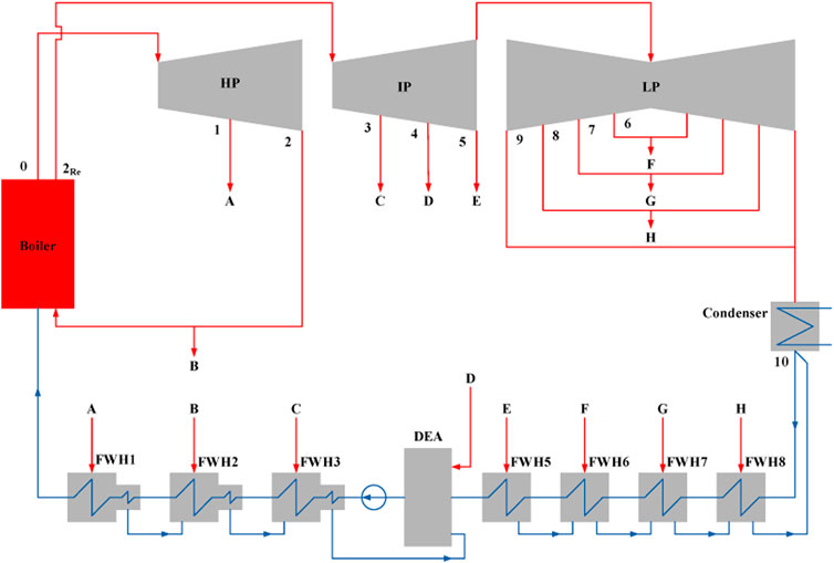
FIGURE 1. Schematic diagram of a typical 300 MW regenerative Rankine cycle power plant with seven feedwater heater (FWH) and one deaerator.
The GAPG plant is based on the RRC power plant. In such a plant, the geothermal energy carried by the geothermal fluid enters a heat exchanger, also termed geo-preheater, sub-system to displace extraction steam for feedwater preheating purpose. The extraction steam replaced by geothermal energy, sometimes termed as saved steam, could then expand further in the lower stages of the steam turbine to generate (more) power. After the feedwater of the RRC power plant is preheated by the geothermal fluid, the geothermal fluid is sent back to the geothermal (injection) well. In order to integrate geothermal energy into the power plant, there are two kinds of arrangement for the heat exchanger sub-system, i.e. the parallel and the series arrangements.
Figure 2 shows the schematic diagram of a GAPG plant with the parallel heat exchanger arrangement. As shown in Figure 2, in a parallel GAPG plant each high pressure FWHs of the RRC power plant (FWH1 to FWH3 in Figure 2) would potentially have one geo-preheater to transfer of the geothermal heat to the feedwater. Namely, each geo-preheater is in parallel with the displaced FWH. The FWHs that could be displaced by geothermal fluid depends on the geothermal fluid temperature. If the temperature of the geothermal fluid can be used to displace FWH1 in Figure 2, the temperature of the geothermal fluid at point G1 must be higher than the temperature of the feedwater at point 1. In this arrangement, shown in Figure 2, the valves A to C require to be adjusted according to the geothermal fluid flow rate to make sure the feedwater temperatures at the exit of each FWH remain unchanged.
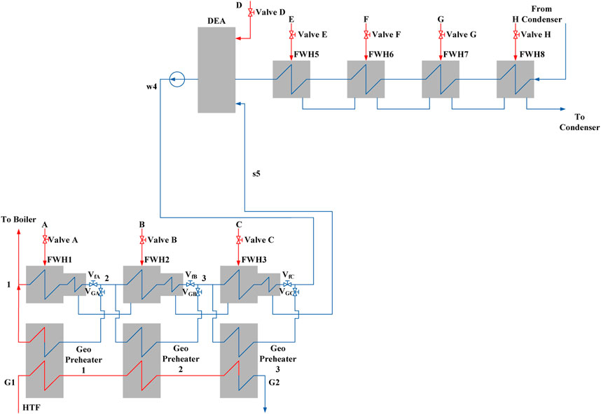
FIGURE 2. Schematic diagram of parallel GAPG plant feedwater heater system.
Figure 3 shows the schematic diagram of the series arrangement of the heat exchanger or geo heater arrangement. As shown in Figure 3, in the series arrangement, there is only two heat exchangers required to preheat feedwater. The geo-preheater 1 is used to displace FWH1 to FWH3 (high pressure FWHs) and the geo-preheater 2, if allowed, is used to displace FWH5 to FWH8 (low pressure FWHs). Similarly (to the parallel arrangement), the Valves A-C, should be adjusted according to the flow rate and the temperature of the geo-fluid at point G1, to make sure the temperature of the feedwater at ws1 remain unchanged.
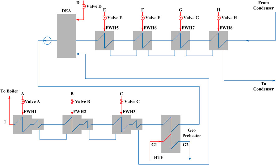
FIGURE 3. Schematic diagram of Series GAPG plant feedwater heater system.
In a GAPG plant, besides the temperature of geo-fluid, there is another factor that would determine which stage of FWH cloud be displaced, that is silica scaling. As the geothermal fluid transfers heat (to feedwater) in geo-preheaters, its temperature drops. When the temperature of geothermal fluid drops, the dissolved silicon dioxide in the geothermal fluid would precipitate from the fluid. the precipitation rate of silicon dioxide is a function of the temperature and silica concentration of the geothermal fluid (Bhuana et al., 2009) (Sudhakar et al., 2018). The precipitation of the silicon dioxide would cause the silica scaling in the heat exchanger and pipelines, which could not be allowed to occur for the safe operation of the plant. Therefore, determining or selecting the right FWH(s) to be displaced, according to the temperature and SiO2 concentration of the geo-fluid, would help to minimize/reduce silica scaling.
To calculate the performance of the GAPG plant, a simulation model has been developed. The simulation model consists of two parts. The first part is used to calculate the GAPG plant’s technical performance, and the second part is used to simulate the silica scaling process that occurred in the geo-preheater.
For a GAPG plant, the simulation of the GAPG plant is actually simulating the energy and mass balance of the FWH system, in which the Matrix Method is often used (Huang et al., 2019). In this paper, the Matrix Method is used to simulate the extraction steam’s mass flow rate variations after geothermal energy integration. Then, the power output of steam turbine can be calculated by using new calculated mass flow rate.
For a GAPG plant with 8 FWHs (including three high pressure FWHs, one deaerator, and four low pressure FWHs), and extraction steam to all high pressure FWHs has been displaced by geothermal energy, the Matrix for FWH system can be expressed as:
Where,
The extraction steam flow rates of each extraction steam at each FWHs with various geothermal energy integration could be calculated by Eq. 1.
In a GAPG plant, the increased power output after geothermal input can be termed as geothermal power output. Therefore, the power efficiency for the whole GAPG plant can be given as:
Where
In a GAPG plant, the silicon dioxide becomes supersaturated as the geo-fluid flows up and quenches to a lower temperature (Chan, 1989). Polymerization happens when the concentration of silica is supersaturated and polymerization proceeds to silica (Gunnarsson and Arnórsson, 2005). The silica scaling takes place in geothermal wells, well pipes, and heat exchanger in the GAPG plant. In geothermal fluid, the rates of silica deposition and polymerization is determined by the PH and salt concentration of geothermal fluid, the residence time, and temperature of geothermal fluid (Gunnarsson and Arnórsson, 2005). The rate of silica deposition can be controlled by adjusting PH through the addition acid of by adding salt (Gunnarsson and Arnórsson, 2005). However, adding salt might still have a negative effect on the pipes of power system and environment of geothermal wells. In the present paper, it is assumed that the solubility of silicon dioxide is only controlled by the temperature of the geothermal fluid and the silica scaling occurs in the heat exchanger system of the GAPG system.
In order to optimise the displacement selections of the GAPG plant with different silica concentrations, the net precipitation rate of silicon dioxide should be calculated. The approaches taken to calculate the silica precipitation and deposition rate of silicon dioxide are quite complex and poorly understood (Brown and Bacon, 2009). A simplified approach using experimental data from Brown and Bacon is used in the present paper to calculate the deposition rate of silicon dioxide.
The precipitation rate of silicon dioxide is mainly determined by the kinetics of amorphous silica in the geothermal fluid. For a geothermal fluid at temperatures ranging from 0 to 300°C, the kinetics of amorphous silica precipitation have been determined by the study of Rimstidt and Barnes (Rimstidt and Barnes, 1980). The reversible reaction of silicon dioxide is shown as:
For this reversible reaction, H4SiO4 (aq) is the precipitation of silicon dioxide. The net precipitation rate can be expressed as (Bhuana et al., 2009):
Where the k+ is the forward rate constant, K is the equilibrium constant and Q is the activity quotient. The Q/K is the degree of saturation (S).
Q is then calculated by
Where, ai is the activity of species i. In the mathematical model,
Rimistidt and Barnes provide a method to calculate k+ and K as a function of the geothermal fluid temperature (Rimstidt and Barnes, 1980). The forward rate constant k+ and the equilibrium constant are given by:
Rimistidt and Barnes provide the a1, a2, b1, c1, c2 which is shown in Table 1.
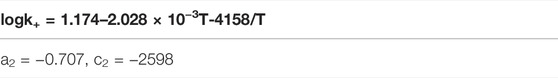
TABLE 1. Temperature functions of the rate constants for silica-water reactions (Rimstidt and Barnes, 1980).
From Eq. 3 to Eq. 6, the net precipitation rate of silica with various geothermal fluid temperature and silica concentration can be expressed as follows:
By using Eq. 6, the silica scaling process in the heat exchanger system of the GAPG plant can be simulated.
A GAPG plant, modified from a 300 MW subcritical RRC power plant, was chosen to be the study case, which is shown in Figure 1. The key parameters of the 300 MW power plant are given in Table 2. As there is no existing GAPG plant, the validation of the GAPG plant is based on the real operation data. In this study, the simulated results of the Rankine cycle plant model have been compared with real operated data with the case study plant. The simulation results for the power output and mass flow rate to the boiler without geothermal input are 303 MW and 241.5 kg/s, while the real operation data are 300 MW and 245.8 kg/s. It can be seen that the comparison results of the GAPG plant show further agreement between the simulation model and reference data.
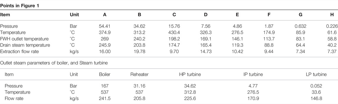
TABLE 2. Key parameters of case study power plant (300 MW subcritical power plants).
According to Figure 1, the 300 MW subcritical RRC power plant has seven feedwater heaters and one deaerator. Four different displacement scenarios have been evaluated in the present study, which are given in Table 3.
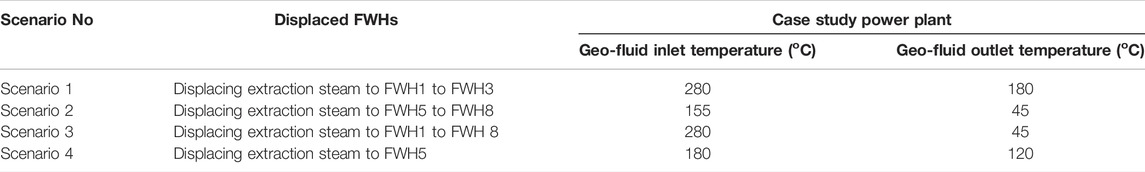
TABLE 3. Case study scenarios.
In Scenario 1, extraction steam to FWH 1 to FWH 3 has been displaced by the geothermal energy. In Scenario 2, the geo-fluid is used to displace extraction steam to FWH5 to FWH8. In Scenario 3, all FHWs have been displaced by the geo-fluid. In Scenario 4, it is assumed that the geothermal fluid from the Scenario 1 (180°C) is used to displace extraction steam at points E only.
In the present study, the minimum temperature difference required for heat transfer in heat exchangers is assumed to be 10°C. At the (production) well, silica is present as quartz, and the concentration of silica in the reservoir ranges from 500 to 700 mg/kg SiO2, which is dependent on the temperature at the well head (Fournier and Rowe, 1966).
In this study, the silicon dioxide precipitation in the geo-preheater system for four scenarios has been simulated. Based on the simulation results, the displacement selection with minimum silica scaling occurring would be selected. The technical performance of the optimal displacement selection with two heat exchanger arrangements has been compared.
Figure 4 presents the variation of silicon dioxide precipitation rate for scenario 1. It can be found from Figure 4 that temperature at which silicon dioxide precipitation starts and the temperature at which its rate reaches maximum depend on the silicon dioxide concentration in the geothermal fluid. When the silicon dioxide concentration is 700 mg/kg, the silicon dioxide begins to precipitate at about 162°C, and the maximum precipitation rate occurs at around 140°C. If the silicon dioxide concentration was to 550 mg/kg, these two temperatures would be 136 and 116°C, respectively. This trend provides a mechanism to decrease the precipitation of silicon dioxide in the Geo-preheater system.
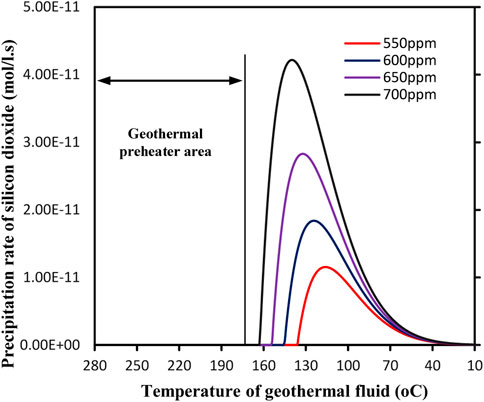
FIGURE 4. Variation of silicon dioxide precipitation rate in the heat exchanger/geo-preheater system for scenario 1.
For Scenario 1, the geo-fluid temperature at the inlet of the heat exchangers for the 300 MW power plant is assumed to be 280°C, and that at the outlet is 180°C. Both temperatures i.e. 280°C and 180°C are well above the precipitation starting temperature, according to Figure 4, even for the highest SiO2 concentration of 700 ppm. In other words, precipitation of silicon dioxide or silica scaling would not occur in Scenario 1.
Figure 5 presents the variations of precipitation rate in the Geo-preheater system of the GAPG plant for Scenario 2. For Scenario 2, the geothermal inlet temperature is 155°C, and the geothermal outlet temperature is 45°C. From Figure 5, it can be found that when the geo-fluid with the concentration of silica at 650 and 700 mg/kg, silicon dioxide begins to precipitate from geo-fluid when they enter the Geo-preheater system. When the concentrations of silica are 550 and 600 mg/kg, about 90 and 80% of the Geo-preheater system are susceptible to fouling by silicon dioxide. This means that Scenario 2 is not suitable for the GAPG plant.
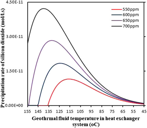
FIGURE 5. Variation of silicon dioxide precipitation rate in the heat exchanger system/geo-preheater for Scenario 2.
The variations of precipitation rate of silicon dioxide in the Geo-preheater system for Scenario 3 is plotted in Figure 6. For Scenario 3, the geothermal inlet and outlet temperatures are 280°C and for 45°C. As can be seen in Figure 6, when the temperature decreases to about 160°C, the geothermal fluid becomes saturated. This means that about 50% of the heat exchanger system is susceptible to fouling by silicon dioxide. This area is the heat exchanger system parallel with low-pressure heat exchanger system. This means that geothermal fluid with the concentration of silica at 550–700 mg/kg is also not suitable for the GAPG plant.
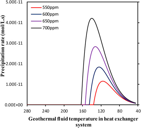
FIGURE 6. Precipitation rate as a function of temperature in the heat exchanger system/geo-preheater for Scenario 3.
Figure 7 presents the variation of silicon dioxide precipitation rate in the heat exchanger system for Scenario 4. In this Scenario, the geothermal temperature at the inlet is about 180°C, which is higher than Scenario 2. However, it can be found that there is still about 30–70% of the heat exchanger system is susceptible to fouling by silicon dioxide for the concentration of silica ranging from 550 to 700 mg/kg. This means that Scenario 4 is also not suitable for the GAPG plant.
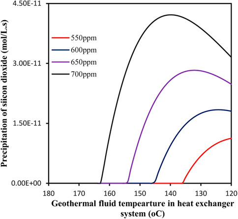
FIGURE 7. Precipitation rate as a function of temperature in the heat exchanger system for Scenario 4.
From Figure 4 to Figure 7, it can be concluded that the best displacement option for the GAPG plant is geo-fluid used to displace all high-pressure FWHs, due to the low silica scaling during the preheating process. Therefore, the technical performance of the GAPG plant with two structures for scenario 1 has been compared.
Figure 8 shows the Extra power output of the steam turbine after different geothermal fluid flow rate integration. Figure 8 shows that when the FWH1 to FWH3 are fully displaced by geothermal energy, the two kinds of GAPG plants have the same power output. When the extraction steam from FWH1 to FWH3 is fully displaced by the geothermal energy, the extra output of steam turbine is 38.9 MW for both of the GAPG plants. When the extraction steam to all high pressure FWHs has been displaced, the power output can be increased by 13%. This means that if the GAPG plant has been operated for reducing boiler consumption. It has protentional to reduce the 13% of carbon dioxide emissions. However, when the extraction steam from FWH1 to FWH3 is partly displaced by the geothermal energy, the power output of the Parallel GAPG plant is higher than the Series GAPG plant. The reason is thought that in the Series GAPG plant, the lower pressure FWH is displaced firstly, this leads to the lower power output than the Parallel GAPG plant.
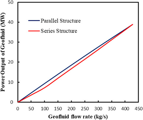
FIGURE 8. The power output of geothermal energy of two kinds of GAPG plants with different geothermal fluid integration.
Figure 9 shows the power output percentage difference of two kinds of GAPG arrangements. As shown in Figure 9, when 50 kg/s geothermal fluid is integrated into two kinds of GAPG plant, the extra output of the Parallel GAPG plant is 29.3% higher than the Series GAPG plant. With the increase of geothermal fluid, the power output difference percentage decrease with the amount of geothermal energy integration.
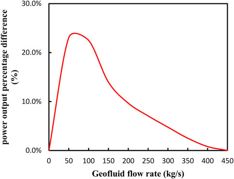
FIGURE 9. Comparison of two kinds of GAPG plant output with same amount of geothermal integration.
Figure 10 shows the power output difference of two kinds of the GAPG plant with different geothermal fluid input. Figure 10 indicates that when the flow rate of geothermal fluid is integrated into two kinds of GAPG plant from 50 to 100 kg/s, the output difference increases from 1.1 to 2.1 MW. After the geothermal fluid flow rate is 100 kg/s, with the increase of geothermal fluid flow rate, the output difference of two kinds of GAPG plant decrease to 0.
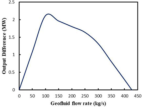
FIGURE 10. Power output difference between two kinds of GAPG plants with the same amount of geothermal integration.
Table 4 shows the hybrid efficiencies of two kinds of GAPG plant with different geothermal energy integration. The hybrid efficiency is defined as the total output of the steam turbine divided by the boiler fuel consumption and geothermal input. As shown by Table 4, with the same amount of geothermal thermal energy input, the two kinds of GAPG plant have almost the same hybrid efficiencies.

TABLE 4. Hybrid efficiencies of two kinds of GAPG plant with different amount of geothermal energy integration.
In a GAPG plant, geothermal fluid at different temperatures is used to displace different grade extraction steam to different stages of feedwater heater. Different displacement selections lead to different technical performances. As the rate of silica deposition is mainly dependent on the temperature of geothermal fluid, adjusting displacement selections can be used to control the silica scaling process that occurred in the heat exchanger system. Also, there are two configurations for the GAPG plant, Parallel, and Series configurations.
In this study, the silica scaling that occurred in the heat exchanger system for different GAPG plant’s displacement selections is simulated to optimise displacement selections. The technical performance for the optimal displacement selections with two structures has been compared. To achieve this aim, a 300 MW subcritical power plant GAPG plant has been used as a case study. Four different displacement selections are used as scenarios for assessment. The results indicate that:
When extraction steam to all high pressure FWHs has been displaced by geo-fluid, there is no silicon dioxide scaling occurred for the GAPG plant. In other words, for scenario 1, there is no energy loss caused by silica scaling with different silico dioxide concentrations in the geothermal fluid.
When extraction steam to all low pressure FWHs has been displaced by geo-fluid, it was found that there is at least 30% of heat exchanger system is susceptible to fouling by silicon dioxide.
Considering the silicon dioxide scaling in the GAPG plant’s heat exchanger system, displacement of extraction steam to all high pressure FWHs is the best displacement selection for the GAPG plant.
When geo-fluid is used to partly displace the extraction steam of the power plant, the Parallel GAPG plant’s geothermal power output is higher than that of the Series GAPG plant. When the geo-fluid flow rate is 100 kg/s, there is a maximum power output difference which is 2.1 MW. However, extraction steam has been fully displaced by the geo-fluid, two kinds of GAPG plants have the same geothermal output. Under this condition, the GAPG plant has protentional to reduce the emissions of Rankine cycle power plant by 13%.
The original contributions presented in the study are included in the article/Supplementary Material, further inquiries can be directed to the corresponding author.
YZ is responsible for the investigation, conceptualization. JQ contributes to conceptualization, methodology, formal analysis. EH contributes to contributes to data curation, formal analysis. QZ contributes to investigation and validation.
The authors declare that the research was conducted in the absence of any commercial or financial relationships that could be construed as a potential conflict of interest.
This paper is supported by the National Natural Science Foundation of China (51875332).
All claims expressed in this article are solely those of the authors and do not necessarily represent those of their affiliated organizations, or those of the publisher, the editors and the reviewers. Any product that may be evaluated in this article, or claim that may be made by its manufacturer, is not guaranteed or endorsed by the publisher.
Agyekum, E. B., Adebayo, T. S., Bekun, F. V., Kumar, N. M., and Panjwani, M. K. (2021). Effect of Two Different Heat Transfer Fluids on the Performance of Solar Tower CSP by Comparing Recompression Supercritical CO2 and Rankine Power Cycles, China. Energies 14 (12), 3426. doi:10.3390/en14123426
Agyekum, E. B., Ali, E. B., and Kumar, N. M. (2021). Clean Energies for Ghana-An Empirical Study on the Level of Social Acceptance of Renewable Energy Development and Utilization. Sustainability 13 (6), 3114. doi:10.3390/su13063114
Battye, D. L., Ashman, P. J., and Nathan, G. J. (2010). “Economic of Geothermal Feedwater Heating for Steam Rankine Cycles,” in Progressing of Australian Geothermal Conference, Adelaide, Australia, November 16–19, 2010 (Australia: Geoscience).
Bhuana, D. S., Ashman, P. J., and Nathan, G. J. (2009). “Silica Deposition in Enhanced Geothermal Systems,” in Progressing of Australia Geothermal Energy Conference, Brisbane, Australia, November 11–13, 2009 (Australia: Geoscience).
Borsukiewicz-Gozdur, A. (2010). Dual-fluid-hybrid Power Plant Co-powered by Low-Temperature Geothermal Water. Geothermics 39, 170–176. doi:10.1016/j.geothermics.2009.10.004
Brown, K. L., and Bacon, L. G. (2009). Pilot Plant Experiments at Wairakei Power Station. Geothermics 38, 64–71. doi:10.1016/j.geothermics.2008.11.004
Buchta, J. (2009). “Green Power from Conventional Steam Power Plant Combined with Geothermal Well,” in Progressing of IEEE International Conference on Industrial Technology, Churchill, Australia, February 10–13, 2009 (IEEE), 2009. doi:10.1109/icit.2009.4939553
Buchta, J., and Wawszczak, A. (2010). “Economical and Ecological Aspects of Renewable Energy Generation in Coal Fired Power Plant Supported with Geothermal Heat,” in Progressing of Electric Power and Energy Conference (EPEC), Halifax, Canada, August 25–27, 2010 (IEEE), 2010. doi:10.1109/epec.2010.5697179
Chan, S. H. (1989). A Review on Solubility and Polymerization of Silica. Geothermics 18, 49–56. doi:10.1016/0375-6505(89)90009-6
Christina, W., Petra, Z., and Andrea, S. (2020). Review of Power-To-X Demonstration Projects in Europe. Front. Energ. Res. 8, 191. doi:10.3389/fenrg.2020.00191
DiPippo, R., DiPippo, E. A., Kestin, J., and Khalifa, H. E. (1981). Compound Hybrid Geothermal-Fossil Power Plants: Thermodynamic Analyses and Site-Specific Applications. J. Eng. Power 103, 797–804. doi:10.1115/1.3230804
DiPippo, R., Khalifa, H., Correia, R., and Kestin, J. (1978). “Fossil Superheating in Geothemral Steam Ower Plants,” in Progressing of the Intersoc Energy. (San Diego, CA: Convers Eng Conference 13th).
Fournier, R., and Rowe, J. (1966). Estimation of Underground Temperatures from the Silica Content of Water from hot springs and Wet-Steam wells. Am. J. Sci. 264, 685–697. doi:10.2475/ajs.264.9.685
Gunnarsson, I., and Arnórsson, S. (2005). Impact of Silica Scaling on the Efficiency of Heat Extraction from High-Temperature Geothermal Fluids. Geothermics 34, 320–329. doi:10.1016/j.geothermics.2005.02.002
Hao, L., Fu, L. J., Zhang, Y., and Xiong, &Y. Y. (2021). A Dynamic and Cooperative Control Strategy for Multi-Hybrid Energy Storage System of DC Microgrid Based on SOC. Front. Energ. Res. 9, 795513. doi:10.3389/fenrg.2021.795513
Hargreaves, J. J., and Jones, R. A. (2020). Long Term Energy Storage in Highly Renewable Systems. Front. Energ. Res. 8, 219. doi:10.3389/fenrg.2020.00219
Huang, C., Hou, H., Hu, E., Yu, G., Peng, H., Yang, Y., et al. (2019). Performance Maximization of a Solar Aided Power Generation (SAPG) Plant with a Direct Air-Cooled Condenser in Power-Boosting Mode. Energy 175, 891–899. doi:10.1016/j.energy.2019.03.133
Kestin, J., DiPippo, R., and Khalifa, H. (1978). Hybrid Geothermal-Fossil Power Plants. Mech. ENgineering 100, 28–35.
Khalifa, H., DiPippo, R., and Kestin, J. (1978). “Geothermal Preheating in Fossil-Fired Steam Power Plants,” in Progressing of Intersoc Energy Convers Eng Conf 13th, San Diego, CA, August 20–25, 1978.
Khalifa, H. (1978). “Hybrid Power Plants for Geo-Pressured Resources,” in Progressing of 5th Annual Geothermal Conference and Workshop, Washington, DC, June 23–25, 1981.
Kolb, G. J. (1998). Economic Evaluation of Solar-Only and Hybrid Power Towers Using Molten-Salt Technology. Solar Energy 62, 51–61. doi:10.1016/s0038-092x(97)00075-3
Kumar, N. M. (2019). Performance of Single-Sloped Pitched Roof Cadmium telluride (CdTe) Building-Integrated Photovoltaic System in Tropical Weather Conditions. Beni-Suef Univ. J. Basic Appl. Sci. 8 (1), 1–9. doi:10.1186/s43088-019-0003-2
Liu, Q., Shang, L., and Duan, Y. (2016). Performance Analyses of a Hybrid Geothermal-Fossil Power Generation System Using Low-Enthalpy Geothermal Resources. Appl. Energ. 162, 149–162. doi:10.1016/j.apenergy.2015.10.078
Qin, J., Hu, E., Nathan, G. J., and Chen, L. (2018). Mixed Mode Operation for the Solar Aided Power Generation. Appl. Therm. Eng. 139, 177–186. doi:10.1016/j.applthermaleng.2018.04.118
Qin, J., Hu, E., and Nathan, G. J. (2017). Impact of the Operation of Non-displaced Feedwater Heaters on the Performance of Solar Aided Power Generation Plants. Energ. Convers. Manage. 135, 1–8. doi:10.1016/j.enconman.2016.12.061
Qin, J., Zhang, Q., Hu, E., Duan, J., Zhou, Y., and Zhang, H. (2022). Optimisation of Solar Aided Power Generation Plant with Storage System Adopting Two Non-displaced Extraction Steam Operation Strategies. Energy 239, 121937. doi:10.1016/j.energy.2021.121937
Kingston Reynolds ThomAllardice Ltd (1980). An Investigation into Hybrid Geothermal/gas Power Plants, Auckland: New Zealand Energy Research and Development Committee.
Rimstidt, J., and Barnes, H. (1980). The Kinetics of Silica-Water Reactions. Geochimica et Cosmochimica Acta 44, 1638–1639. doi:10.1016/0016-7037(80)90220-3
Setiawan, F. A., Rahayuningsih, E., Petrus, H. T. B. M., Nurpratama, M. I., and Perdana, I. (2019). Kinetics of Silica Precipitation in Geothermal Brine with Seeds Addition: Minimizing Silica Scaling in a Cold Re-injection System. Geothermal Energy 7 (22). doi:10.1186/s40517-019-0138-3
Seyfettin, G. (2021). Can, “Steam Turbine—Quo Vadis? Front. Energ. Res. 8, 612731. doi:10.3389/fenrg.2020.612731
Sudhakar, K., Samykano, M., and Jayaseelan, V. (2018). “BIPV Market Growth: SWOT Analysis and Favorable Factors,” in 2018 4th International Conference on Electrical Energy Systems (ICEES), Chennai, India, February 7–9, 2018 (IEEE), 412–415.
Waqar, A., Shahbaz Tanveer, M., Ahmad, J., Aamir, M., Yaqoob, M., and Anwar, F. (2017). Multi-objective Analysis of a CHP Plant Integrated Microgrid in Pakistan. Energies 10, 1625. doi:10.3390/en10101625
Zhang, G., Cao, Y., Cao, Y., Li, D., and Wang, L. (2017). Optimal Energy Management for Microgrids with Combined Heat and Power (CHP) Generation, Energy Storages, and Renewable Energy Sources. Energies 10, 1288. doi:10.3390/en10091288
Zhang, N., Hou, H., Yu, G., Hu, E., Duan, L., and Zhao, J. (2019). Simulated Performance Analysis of a Solar Aided Power Generation Plant in Fuel Saving Operation Mode. Energy 166, 918–928. doi:10.1016/j.energy.2018.10.014
Zhao, Y., Du, B., Chen, S., Zhao, J., Gong, Y., Bu, X., et al. (2021). Thermo-Economic Comparison Between Organic Rankine Cycle and Binary-Flashing Cycle for Geothermal Energy. Front. Energ. Res. 9, 759872. doi:10.3389/feart.2021.759872
Zhao, Y., Hong, H., and Jin, H. (2016a). Appropriate Feed-In Tariff of Solar-Coal Hybrid Power Plant for China's Inner Mongolia Region. Appl. Therm. Eng. 108, 378–387. doi:10.1016/j.applthermaleng.2016.07.062
Zhao, Y., Hong, H., and Jin, H. (2016b). Effectiveness Analysis of Solar Replacement Scenarios in a Typical Solar–Coal Hybrid System. Energy Sourc. A-Recovery Utilization Environ. Effects 38, 1798–1804. doi:10.1080/15567036.2014.1004003
Zhao, Y., Hong, H., and Jin, H. (2016c). Effectiveness Analysis of Solar Replacement Scenarios in a Typical Solar–Coal Hybrid System. Energ. Sourc. Part A-Recovery Utilization Environ. Effects 38, 1969–1974. doi:10.1080/15567036.2014.1004003
Zhou, C., Doroodchi, E., and Moghtaderi, B. (2014). Assessment of Geothermal Assisted Coal-Fired Power Generation Using an Australian Case Study. Energ. Convers. Manage. 82, 283–300. doi:10.1016/j.enconman.2014.03.011
Keywords: geothermal aided power generation, configuration, power system, silica scaling, displacement selection
Citation: Zhou Y, Qin J, Hu E and Zhang Q (2022) Technical Performance Optimization of a Novel Geothermal Hybrid Power Generation System. Front. Energy Res. 10:824421. doi: 10.3389/fenrg.2022.824421
Received: 30 November 2021; Accepted: 07 January 2022;
Published: 09 May 2022.
Edited by:
Idiano D'Adamo, Sapienza University of Rome, ItalyReviewed by:
Nallapaneni Manoj Kumar, City University of Hong Kong, Hong Kong SAR, ChinaCopyright © 2022 Zhou, Qin, Hu and Zhang. This is an open-access article distributed under the terms of the Creative Commons Attribution License (CC BY). The use, distribution or reproduction in other forums is permitted, provided the original author(s) and the copyright owner(s) are credited and that the original publication in this journal is cited, in accordance with accepted academic practice. No use, distribution or reproduction is permitted which does not comply with these terms.
*Correspondence: Jiyun Qin, cWluLmppeXVuQGZveG1haWwuY29t
Disclaimer: All claims expressed in this article are solely those of the authors and do not necessarily represent those of their affiliated organizations, or those of the publisher, the editors and the reviewers. Any product that may be evaluated in this article or claim that may be made by its manufacturer is not guaranteed or endorsed by the publisher.
Research integrity at Frontiers
Learn more about the work of our research integrity team to safeguard the quality of each article we publish.