 Xinan Yu1,2
 Xiaoping Li
- 1State Key Laboratory of Oil and Gas Reservoir Geology and Development Engineering, Southwest Petroleum University, Chengdu, China
- 2Chongqing University of Science and Technology, Chongqing, China
- 3Exploration and Development Research Institute, Shengli Oilfield, Sinopec, Dongying, China
Multi-component thermal fluid (MCTF) huff and puff technology is an innovative heavy oil development technology widely used in China offshore oilfields. MCTFs mainly include steam, N2 and CO2. Under high temperature and high pressure, the physical and chemical reactions between thermal fluids and rocks occur, damaging the reservoir permeability and production effect. In this paper, 16 groups of core comparison experiments were carried out by MCTF device, the influence of original permeability, temperature and component on reservoir damage was quantitatively studied, and a mathematical model was established. Finally, the influence of reservoir damage on heavy oil development was investigated through numerical simulation. The experimental study reveals that MCTF has an obvious damage effect on the reservoir, where temperature and PV dominate the damage degree; with the increase of MCTF injection volume (PV), the core permeability rapidly decreases initially and stabilizes later (>6 PV). The numerical simulation results show that reservoir damage could lead to a recovery drop by 6.9% during MCTF development; on the premise of considering reservoir damage, MCTF huff and puff will further improve oil recovery by 9.68% compared with pure steam. The research is of great significance for understanding the production law of MCTF huff and puff and helpful for promoting the development of offshore heavy oil reservoir.
1 Introduction
At present stage, the potential of conventional sandstone reservoirs has gradually declined, and heavy oil reservoirs have become one of the key areas to increase production in China (Jiang et al., 2020; Li, 2021; Yang, 2021). Among heavy oil reservoirs, offshore reservoirs attract more attention because of good physical conditions and high production capacity (Deng, 2006; Deng et al., 2021). However, thermal recovery methods widely used in onshore heavy oil reservoirs are not suitable for offshore development platforms due to the requirements of large fluid volume and equipment area (Zhang et al., 2014). Offshore heavy oil development platform has been seeking a new thermal recovery method, where injection material is easy to obtain, transport and store, and the equipment is light and able to produce enough heat. Fortunately, these requirements coincide with the target of aeroengine, which provides a new idea of thermal recovery technology for offshore heavy oil reservoirs.
To reduce weight and generate more heat energy, aeroengines use multiple thermal fluids to obtain powerful kinetic energy. First, fuel and air are pressurized into the combustion chamber. The combustion will produce a high temperature of 2000°C and N2 and CO2 with high temperature is discharged. At the same time, the water around the combustion chamber is rapidly gasified at high temperature and mixed with N2 and CO2 in the mixing chamber to form a large number of high-temperature gases, which are sprayed at high speed to form a strong thrust. The basic schematic diagram of aeroengine device is shown in Figure 1. The multi-component fluid heating method can make full use of heat energy, and its thermal efficiency can reach 95%. Compared with the conventional method, more than 16% hot steam can be produced with the same fuel.
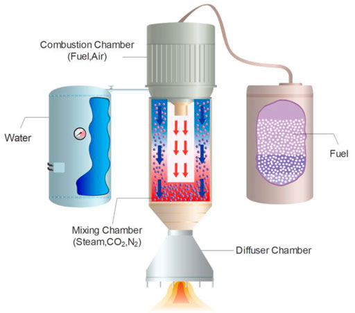
FIGURE 1. Schematic diagram of aeroengine device.
Inspired by the mechanical principle of aeroengine, offshore development platform develops heat engine equipment and forms the MCTF recovery technology. The technology ignites the fuel and air to obtain a large amount of heat, gasifies the formation water to produce sufficient steam, and then mixes N2 and CO2 to inject into the formation. The application of MCTF recovery technology in offshore heavy oil field has achieved good results. In 2008, CNOOC adopted MCTF huff and puff thermal recovery technology in Nanpu 35-2 offshore heavy oil field. The production of one well is as high as 620 t/d, which is 2–3 times that of cold recovery methods (Liu et al., 2011). In 2009, SINOPEC Shengli Oilfield used MCTF huff and puff technology in well GDN5-604. The water cut of this well decreased by 27% within half a year, the daily oil production increased by about 3 times, and the cumulative oil increase was 1009t (Ren, 2013).
However, with more cycles of MCTF huff and puff, it is found that the production effect is gradually lower than theoretical expectation, in which reservoir damage is an important reason. The fluid temperature at the outlet of new thermal recovery equipment reaches 150–300°C and the pressure is about 20 MPa. In addition, the compaction and cementation of offshore heavy oil reservoir are usually poor. Under such high temperature and pressure environment, complex physical and chemical reactions will occur between hot steam, CO2, N2, formation fluid and rock, which will cause continuous damage to the reservoir in the process of long-term huff and puff production, making it difficult to accurately predict, evaluate and adjust reservoir development.
Scholars have carried out a series of studies on MCTF technology, but most of the studies focus on enhanced oil recovery (EOR) mechanisms such as reducing crude oil viscosity and interfacial tension and increasing reservoir energy. There are few studies focusing on the formation damage. Actually, there are more research on formation damage caused by hot steam components. These studies found that in the process of steam huff and puff or steam flooding, the PH value of steam reaches 8–9. Gradually, the pore structure and physical properties of reservoir rock change greatly on the flowing path of steam, which has a serious impact on the later development effect (Qing-Xiang C and Yi-Kui, 2012). Physical simulation experiments show that steam can swell clay, block pore throat, dissolve quartz particles and silicates in reservoir (Reed, 1980; McCorriston et al., 1981; Bennion et al., 1992; Liu et al., 2017). After mineral dissolution, the content of SiO2, Al2O3 and K2O in solution will increase, and these metal ions will produce analcime, stone, calcium zeolite and calcite, which further block the pore throat (Pang et al., 2010). Apart from reacting with rocks, steam also interacts with crude oil to produce asphalt precipitation, which ultimately reducing the reservoir permeability (Mohnot et al., 1987; Okoye et al., 1991; Fan, 2002). In addition, CO2 is a typical acid gas, which will increase the concentration of CO32- and HCO3− in the reservoir, make it easier to generate calcium carbonate precipitation, and then block the formation to cause damage. Bikkina et al. confirmed that the long-term existence of injected CO2 and high salinity brine will cause significant damage to the physical properties of the reservoir (Bikkina et al., 2016). Wang Qian et al. studied the impact of CO2, formation water and rock interaction on heterogeneous reservoirs in the development mode of CO2-Water Alternating Gas (CO2-WAG). They found that after CO2-WAG, the permeability of high, medium and low reservoirs decreased by 29.4, 16.8 and 6.9% respectively. The above research was only performed under conventional development methods such as steam huff and puff, CO2 drive and CO2-WAG etc. However, in the process of MCTF huff and puff, the temperature, pressure and composition are different. At present, there are few studies focusing on the reservoir damage of MCTF huff and puff development method. It is necessary to further strengthen relevant research to provide guidance for offshore heavy oil reservoir development.
Based on the cores from heavy oil reservoir, this paper studies the reservoir damage degree of MCTF huff and puff by high temperature and high pressure resistant experimental equipment. According to the experimental data, we establish a mathematical model to characterize reservoir damage, and use the numerical simulation method to compare the development effect considering reservoir damage on oilfield scale.
2 Experimental Method
2.1 Experimental Equipment
The experimental flow of MCTF reservoir damage is shown in Figure 2. The system consists of five parts: Oil-water injection system (constant pressure and speed pump, steam generator, intermediate container, etc.), Gas injection system (N2 cylinder, CO2 cylinder, gas mass flow controller, etc.), Temperature control system (temperature controller, heating belt, temperature sensor, etc.,), Model system (heating spiral tube, core holder, back pressure controller, etc.,) and Metering system (condenser, measuring cylinder, etc.). The constant pressure and speed pump is ISCO 260D pump. Its pressure range is 0–50 MPa, the flow rate range is 0.001–80 ml/min, and the accuracy is ±0.5%. The two manual pumps’ pressure range is 0–50 MPa, and the accuracy is ±2%. The measuring range of pressure gage is 0–1.0 Mpa and the accuracy is 0.001 Mpa. The core holder is designed for 2.54 cm core and can withstand 35 MPa pressure and 400°C temperature.
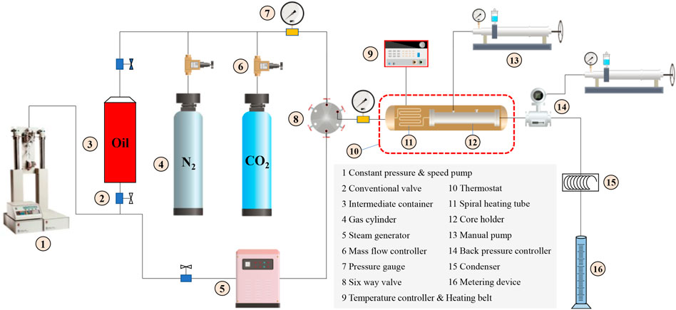
FIGURE 2. Experimental equipment and flow chart.
2.2 Experimental Design
When the offshore platform works with MCTF generators, the water for one-time consumption is about 1,000–2500 t, producing CO2 about 3500–7000 Nm3 and N2 about 16,000–35000 Nm3. Taking the typical heavy oil reservoir in Bohai Sea as an example, the reservoir pressure is 12.7 MPa and the temperature is 43°C. Under the formation conditions, the volume of CO2 is about 30–55 m3 and N2 is about 145–275 m3. And the amount of steam injected on site is generally measured by water consumption. According to the fluid proportion and experimental situation, the injection parameters of each component are determined as follows: steam 1.0 ml/min (L), CO2 0.032 ml/min (g) and N2 0.150 ml/min (g).
This experiment uses oilfield crude oil and simulated formation water. The gas is 99.99% CO2 and N2. The core is obtained from a heavy oil reservoir of China. The average content of clay minerals in the core samples is 20.0%, including 34.1% kaolinite, 27.0% illite-montmorillonite mixed-layer, 24.3% illite and 14.6% chlorite. 16 groups of experiments were designed and divided into 4 groups according to the permeability level of cores, marked as K1 (≈1200 mD), K2 (≈900 mD), K3 (≈700 mD), K4 (≈500 mD). Four experiments were carried out for each group of cores to study the effects of permeability (Table 1), temperature (Table 2), component proportion of steam, N2 and CO2 (Table 3) on reservoir damage. The experimental parameters are as follows:

TABLE 1. Experimental parameter scheme for studying the influence of permeability.
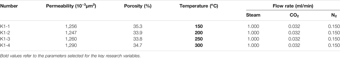
TABLE 2. Experimental parameter scheme for studying the influence of temperature.
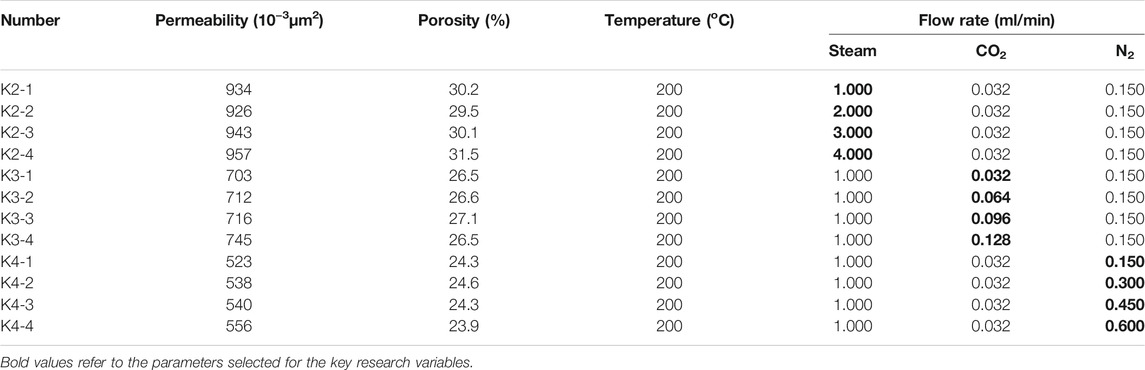
TABLE 3. Experimental parameter scheme for studying the influence of composition.
2.3 Experimental Procedures
First, record the weight of the dry core and vacuum the core for 12 h. Then saturate the core pore volume with the prepared formation water and weigh the wet core. Calculate the core’s porosity according to the weight difference between wet core and dry core, water density and core size. In addition, measure the core’s initial permeability by formation water flooding method. To simulate the original oil saturation, the core oil saturation is made by oil displacement water. After the cores are ready, keep the cores and equipment at specified temperature for 24 h to maintain at the same temperature. Connect the experimental equipment, open the air pump and valve, start the multi-component hydrothermal huff and puff experiment according to the parameter design scheme, record the experimental data, and invert the permeability change curve according to the pressure change. When the pressure is basically stable within 1 h, stop the experiment (actually about 24 PV) and remeasure the permeability with formation water. Finally, change the temperature, proportion and other experimental parameters, and repeat the above experimental steps.
3 Analysis of Experimental Results
In order to quantitatively evaluate the damage degree of reservoir permeability, two damage coefficients are defined, where Dremain = (k/ki) × 100%, Dloss = (ki-k)/ki × 100%. k is current permeability, ki is original permeability and they can be calculated according to the initial permeability and pressure change ratio. To determine the key influencing factors, we study the influence of original permeability level, temperature and thermal fluid component proportion on reservoir damage degree.
3.1 The Influence of Permeability on Damage Degree
Table 4 shows the final permeability of cores with different permeability levels after MCTF flooding. Experiments show that the MCTF will bring obvious damage to the core permeability, and the smaller the permeability, the higher the damage degree.
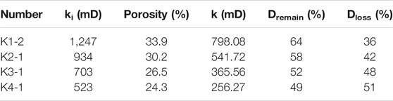
TABLE 4. Permeability damage of cores with different permeability levels.
The permeability damage coefficient Dloss of K4-1 core is the largest. Figure 3 shows that after the thermal fluid flow, the adhesion of clay minerals becomes worse in a short time. It is easier for the thermal fluid to carry it to migrate, resulting in the blockage of original pores, which may be one of the reasons for the decline of core’s permeability (Zhuang, 2017). And the experimental results show that the smaller the original permeability of the core, the greater the permeability damage. Because the pores of low permeability cores are more likely to be blocked by migrating particles. In general, when the permeability changes by 2.4 times (1247 mD to 523 mD), the reservoir permeability damage only changes by 1.3 times (36–51%). The original permeability has limited influence on the degree of reservoir damage.
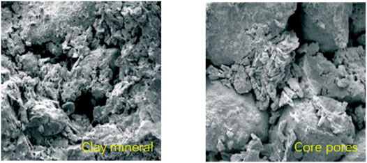
FIGURE 3. The distribution of clay minerals and pores in the core.
3.2 The Influence of Temperature on Damage Degree
In this paper, the core with K1 (≈1,200) permeability level is used to carry out four groups of temperature influence experiments at 150, 200, 250 and 300°C. The experimental results are as Table 4.
Table 5 shows the permeability damage degree at different temperatures. Under the same conditions, the higher the temperature of MCTF, the greater damage to the permeability. The experimental data show that when the temperature is 250°C, the permeability will be reduced to half of the original permeability. And when the experimental temperature changes twice (150–300°C), the degree of permeability damage will increase by 2.3 times (28–68%), so temperature is one of the important factors affecting reservoir damage.
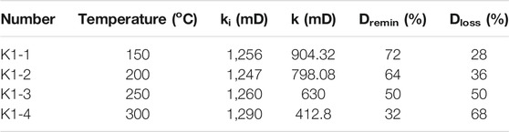
TABLE 5. Permeability damage of cores with different temperature.
3.3 The Influence of Component Proportion on Damage Degree
In this experiment, the proportion of steam, CO2 and N2 in various thermal fluids was adjusted. Four gradient parameters were set for each component, so 12 groups of experiments were carried out to study the effect of different components proportion on reservoir damage.
3.3.1 The Influence of Stream Proportion on Damage Degree
When steam is injected at different flow rates, the component proportion of steam, CO2 and N2 injected will change. In this experiment, four different steam flow rates of 1, 2, 3 and 4 ml/min were tested.
Table 6 shows the final damage results caused by MCTF. It is found that the damage degree of permeability in different steam proportion is basically the same. It shows that the change of steam proportion has little impact on reservoir damage. Because the change of steam content is very limited.
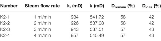
TABLE 6. Permeability damage of cores with different stream proportion.
3.3.2 The Influence of CO2 Proportion on Damage Degree
In this experiment, four different CO2 flow rates of 0.032, 0.064, 0.096, 0.128 ml/min were tested.
Table 7 show that the amount of CO2 injected affect the damage of multicomponent thermal fluid to reservoir weakly. And the higher the proportion of CO2, the smaller the degree of reservoir damage. Under the condition of high temperature and high pressure, the injected CO2 reacts with water to generate carbonic acid, which can reduce the pH value of the reservoir, while the acidic environment will increase the stability of clay minerals (Yuan et al., 2017; Wang et al., 2018; Lanxiang et al., 2019), so it will reduce the degree of damage caused by multicomponent thermal fluid. When the proportion of CO2 changes by 4 times, the reservoir damage degree is less than 1.2 times (48–41%).
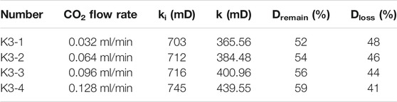
TABLE 7. Permeability damage of cores with different CO2 proportion.
3.3.3 The Influence of N2 Proportion on Damage Degree
We carried out experiments on four flow rates between 0.15–0.6 ml/min. Table 8 show that with the increase of N2 proportion, the degree of reservoir damage decreases slightly, but this effect is very small. When the proportion of N2 changes 4 times (0.15–0.6 ml/min), the damage degree of hot fluid reservoir is only reduced by 2% (51–48%).
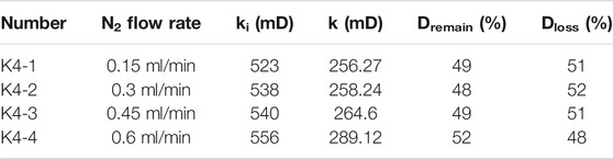
TABLE 8. Permeability damage of cores with different N2 proportion.
4 Mathematical Model of Reservoir Damage Caused by Multicomponent Thermal Fluid
Figure 4 is the dimensionless curve of permeability (Dremain = k/ki × 100%) change in the experimental process at different temperatures. The permeability coefficient (Dremain) is affected by the temperature and the PV (Pore Volume). With the MCTF displacement undergoes, the core permeability decreases rapidly in the early stage and slows down in the later stage. At 150°C, 200°C, 250 °C and 300°C, the reservoir damage caused by the first 6 PV for 95.3, 95.0, 96.0 and 98.5% of their total damage respectively, so the PV of thermal fluid injection is one of the most important factors affecting reservoir damage.
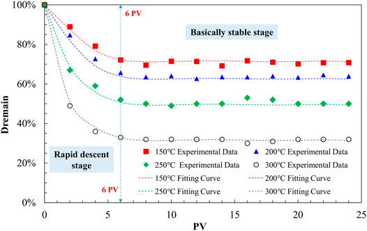
FIGURE 4. Change curve of core permeability with injected multicomponent thermal fluid PV.
In order to establish a mathematical model to calculate the damage degree of multicomponent thermal fluid to the reservoir, we analyzed the susceptibility of all influencing factors (as shown in Figure 5). The analysis shows that the relative importance of the influencing factors is: Temperature > PV > Permeability > CO2 > N2 > Steam. Note that this conclusion is only the relative importance when the experimental parameters change, not the absolute importance. For example, steam may has a great impact on reservoir damage, but its relative change is small when it changes on the basic level. Among them, temperature and PV are the most important factors affecting the degree of reservoir damage. Considering the calculation ability and accuracy, selecting these two factors to establish a mathematical model should have a good prediction effect. Therefore, we establish the following polynomial mathematical model (Eq. 1). All the coefficients are fitted according to the experimental data (as shown in the (Table 9), and a good fitting effect is obtained (Figure 4).
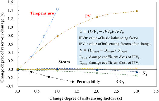
FIGURE 5. Sensitivity analysis of influencing factors.

TABLE 9. Table of parameters for permeability damage coefficient formula.
5 Numerical Simulation
In order to quantitatively study the effect of Steam-N2-CO2 MCTF huff and puff on the actual reservoir scale, CMG was used to compare several development indexes of steam and MCTF methods. The MCTF numerical simulation method considers the damage mechanism by adding Eq. 1 to the control equation.
Based on the above settings, a heavy oil reservoir mechanism model was established. Table 10 lists the key parameters of the reservoir model. The dimension of the model is 51 × 51 × 10, and the block size is 2 m, 2 m and 1 m for DX, DY, DZ, respectively.
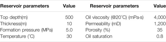
TABLE 10. Key parameters of the reservoir.
Four numerical simulation experiments are designed. The specific parameters of the numerical simulation are shown in Table 11.
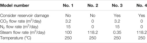
TABLE 11. Key parameters of the numerical simulation.
5.1 Comparison of Thermal Cavity Expansion
Figure 6 shows the temperature spread range of different models in 2.5 years, reflecting the thermal cavity of thermal fluid puff and huff.
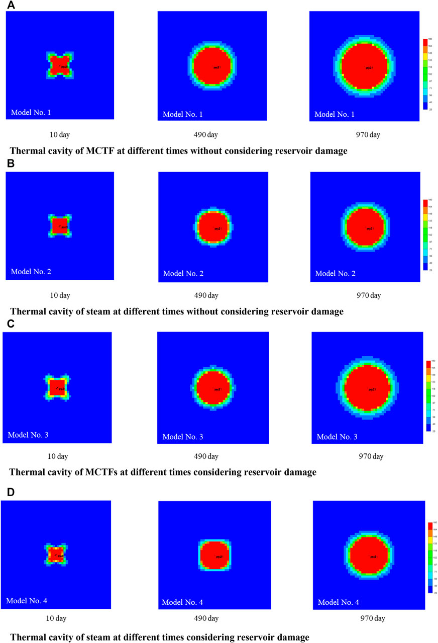
FIGURE 6. Thermal cavity of different numerical simulation models. (A) Thermal cavity of MCTF at different times without considering reservoir damage, (B) Thermal cavity of steam at different times without considering reservoir damage, (C) Thermal cavity of MCTFs at different times considering reservoir damage, (D) Thermal cavity of steam at different times considering reservoir damage.
In the early stage, the thermal cavities of model 1 and 3 are almost the same. In the middle stage, the thermal cavity in model 3 is relatively small because the reservoir damage increases the flow resistance. In the later stage, the thermal cavity of model 1 and 3 tend to be consistent too. Because their injection amounts are equal, there is little difference in the final expansion area of thermal cavities after a long time. Comparing model 1 with model 2, model 3 and model 4 respectively, it is found that the spread range of multicomponent thermal fluid is greater than that of steam, in which N2 plays an important role (Clara et al., 2000; Gutierrez et al., 2006; Feng et al., 2013; Malinda et al., 2021).
5.2 Comparison of Viscosity Reduction Effect Near Well Zone
Figure 7 shows the change of heavy oil viscosity near the production well after injection of thermal fluid. It shows that the viscosity of heavy oil near the production well decreases rapidly, and the viscosity reduction effect of multicomponent thermal fluid is weak, which is better than that of hot steam. This shows that the thermal viscosity reduction of steam is the dominant factor, and CO2 in MCTF can reduce the viscosity of heavy oil (Klins and Ali, 1982), which also plays a positive role in viscosity reduction of heavy oil near the well.
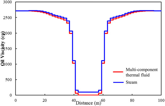
FIGURE 7. Viscosity curve of heavy oil near the production well.
5.3 Comparison of the Influence of Reservoir Damage on the Development Effect of MCTF
This paper compares the production effect of MCTF huff and puff with and without reservoir damage. The oil recovery rate and recovery factor under the two conditions are shown in Figure 8. When reservoir damage is not considered, the reservoir recovery is 41.12%, when reservoir damage is considered, the reservoir recovery is 34.22%, and the recovery is reduced by 6.9%.
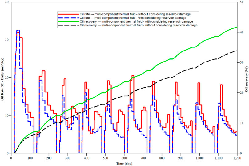
FIGURE 8. Production curve of multicomponent thermal fluid huff and puff.
5.4 Comparison of Development Effects Between MCTF and Steam Huff and Puff
The MCTF includes steam N2 and CO2, and its mechanism is more complex than pure steam huff and puff. In this paper, the difference between EOR and reservoir damage is quantitatively studied by numerical simulation. It is found that when reservoir damage is not considered, the recovery efficiency of multicomponent thermal fluid and steam huff and puff is 41.12 and 30.02% (Figure 9). The recovery efficiency of multicomponent thermal fluid is 11.1% higher than hot steam. When considering reservoir damage, the recovery factors of multicomponent thermal fluid and steam huff and puff are 34.22 and 24.54% (Figure 10). The recovery factor of multicomponent thermal fluid is 9.68% higher than hot steam. The oil recovery effect of MCTF is obviously better than steam. This is consistent with the law that the viscosity reduction effect and the thermal cavity range of MCTF is better than hot steam.
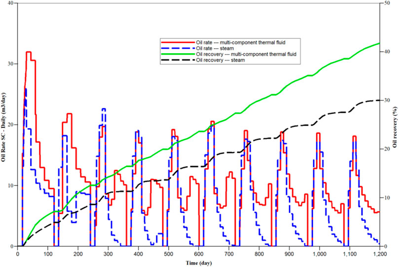
FIGURE 9. Production curve without considering reservoir damage.
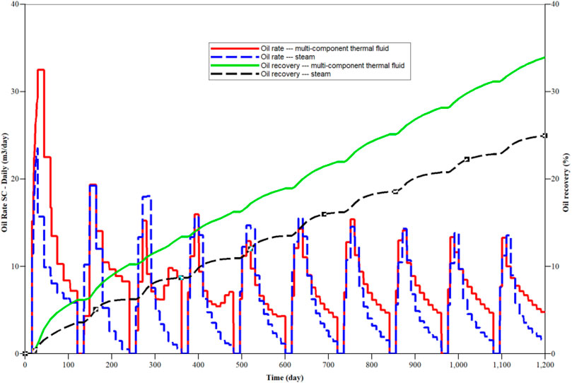
FIGURE 10. Production curve considering reservoir damage.
6 Conclusion
This paper quantitatively studies the influence of multiple factors on reservoir damage through core experiments. Using numerical simulation method, the development effect of multicomponent thermal fluid on heavy oil reservoir is compared and studied at the reservoir scale, and the following conclusions are obtained:
1) Long term MCTF huff and puff development will cause reservoir permeability damage. The greater the original permeability of the reservoir, the lower the degree of reservoir damage; the greater the temperature and fluid PV, the higher the degree of reservoir damage; the changes of steam, N2 and CO2 have little effect on the degree of reservoir damage.
2) The damage of multicomponent thermal fluid to reservoir permeability can be divided into two stages: rapid decline stage (<6 PV) and basic stability stage (>6 PV);
3) Temperature and PV are the most important factors affecting the degree of reservoir damage. Based on temperature and PV, a polynomial mathematical model for predicting permeability damage is established in this paper. The model has a good fitting effect on the experimental data.
4) Reservoir damage caused by MCTF huff and puff has an impact on heavy oil development. The simulation results show that the recovery factor will decrease by 6.9% when considering reservoir damage.
5) On the premise of considering reservoir damage, compared with pure steam huff and puff, multicomponent thermal fluid huff and puff will further improve oil recovery by 9.68%, which is related to the larger spread range of multicomponent thermal fluid and better viscosity reduction effect.
Data Availability Statement
The original contributions presented in the study are included in the article/Supplementary Material, further inquiries can be directed to the corresponding author.
Author Contributions
XY, manuscript writer and numerical simulation; XL, data processing; MC, experimental operation GW, experimental operation XL, numerical simulation and project management.
Funding
The study was supported by the following funds: Joint fund for enterprise innovation and development of National Natural Science Foundation of China: basic research on efficient development mechanism and key technologies of multi- component thermal fluid in heavy oil reservoir (U20B6003).
Conflict of Interest
XL, MC, and GW were employed by the company Shengli Oilfield, Sinopec.
The remaining authors declare that the research was conducted in the absence of any commercial or financial relationships that could be construed as a potential conflict of interest.
Publisher’s Note
All claims expressed in this article are solely those of the authors and do not necessarily represent those of their affiliated organizations, or those of the publisher, the editors and the reviewers. Any product that may be evaluated in this article, or claim that may be made by its manufacturer, is not guaranteed or endorsed by the publisher.
References
Bennion, D. B., Thomas, F., and Sheppard, D. (1992). “Formation Damage Due to mineral Alteration and Wettability Changes during Hot Water and Steam Injection in clay-bearing sandstone Reservoirs,” in SPE Formation Damage Control Symposium, Lafayette, LA (Society of Petroleum Engineers). doi:10.2118/23783-ms
Bikkina, P., Wan, J., Kim, Y., Kneafsey, T. J., and Tokunaga, T. K. (2016). Influence of Wettability and Permeability Heterogeneity on Miscible CO2 Flooding Efficiency. Fuel 166 (FEB.15), 219–226. doi:10.1016/j.fuel.2015.10.090
Clara, C., Durandeau, M., Quenault, G., and Nguyen, T.-H. (2000). Laboratory Studies for Light-Oil Air Injection Projects: Potential Application in Handil Field. SPE Reservoir Eval. Eng. 3 (03), 239–248. doi:10.2118/64272-pa
Deng, Y. (2006). Discussion on the Genesis of Heavy Oil in Bohai Oil Region. China Offshore Oil and Gas 06, 361–364+371.
Deng, Y., Xu, J., and Sun, L. (2021). Major National Science and Technology Projects Support CNOOC to Increase Reserves and Production. Pet. Sci. Tech. Forum 40 (03), 56–71.
Fan, H. (2002). The Study on Composition Changes of Heavy Oils during Steam Stimulation Processes. Fuel 81 (13), 1733–1738.
Feng, X., Jing-Song, L. I., and Cheng-Xiang, Q. I. (2013). Influence Factors Analysis for Complex Thermal Fluid Simulation in Heavy Oil Reservoirs. Sci. Tech. Eng. 13 (2), 468–471.
Gutierrez, D., Kumar, V., and Moore, R. (2006). Air Injection and Waterflood Performance Comparison of Two Adjacent Units in buffalo Field: Technical analysis[C]//SPE/DOE Symposium on Improved Oil Recovery.
Jiang, Q., You, H., and Pan, J. (2020). Preliminary Discussion on Current Status and Development Direction of Heavy Oil Recovery Technologies. Spec. Oil Gas reservoirs 27 (06), 30–39.
Klins, M. A., and Ali, S. M. F. (1982). Heavy Oil Production by Carbon Dioxide Injection. J. Can. Pet. Technol. 21 (5), 64–72. doi:10.2118/82-05-06
Lanxiang, S., Peng, L., and Dehuang, S. (2019). Improving Heavy Oil Recovery Using a Top-Driving, CO2-assisted Hot-Water Flooding Method in Deep and Pressure-Depleted Reservoirs. J. Pet. Sci. Eng. 173, 922–931.
Li, Y. (2021). Breaking the Problem of Super Heavy Oil -- Heavy Oil Development Technology in Xinjiang Has Reached the International Leading Level. Chin. Pet. Enterprises 21, 16–25+143.
Liu, P., Zheng, H., and Wu, G. (2017). Experimental Study and Application of Steam Flooding for Horizontal Well in Ultra-heavy Oil Reservoirs. J. Energ. Resour. Technol.-Trans. ASME. 139 (1), 1–9. doi:10.1115/1.4035254
Liu, X., Zhang, F., and Huang, K. (2011). Preliminary Study on thermal Recovery of Nanpu 35-2 Offshore Heavy Oil Field. Reservoir Eval. Dev. 21, 4.
Malinda, M. T., Setiati, R., Azizi, M. A., and Simbolon, Y. F. (2021). Effect of Improvement of Temperature and Gas Amount on Nitrogen Flooding. IOP Conf. Ser. Earth Environ. Sci. 819 (1). doi:10.1088/1755-1315/819/1/012024
McCorriston, L. L., Demby, R. A., and Pease, E. C. (1981). “Study of Reservoir Damage Produced in Heavy Oil Formations Due to Steam Injection,” in SPE Annual Technical Conference and Exhibition, San Antonio, TX (Society of Petroleum Engineers). doi:10.2118/10077-ms
Mohnot, S. M., Bae, J. H., and Foley, W. L. (1987). A Study of mineral/alkali Reactions. SPE Reservoir Eng. 2 (04), 653–663. doi:10.2118/13032-pa
Okoye, C., et al. (1991). “Formation Damage in Heavy-Oil Formation during Steamflooding,” in SPE Asia-Pacific Conference, Perth, Australia (Society of Petroleum Engineers). doi:10.2118/22980-ms
Pang, Z.-X., Liu, H.-Q., and Liu, X.-L. (2010). Characteristics of Formation Damage and Variations of Reservoir Properties during Steam Injection in Heavy Oil Reservoir. Pet. Sci. Tech. 28 (5), 477–493. doi:10.1080/10916460902780335
Qing-Xiang C, H. Z., and Yi-Kui, K. (2012). The Chemical Reaction in Thermal Recovery of Heavy Oil and its Countermeasures. Journal of Oil and Gas Technology. J. Oil Gas Tech. 34 (9), 269–272.
Reed, M. G. (1980). Gravel Pack and Formation sandstone Dissolution during Steam Injection. J. Pet. Tech. 32 (06), 941–949. doi:10.2118/8424-pa
Wang, C., Liu, P., Wang, F., Atadurdyyev, B., and Ovluyagulyyev, M. (2018). Experimental Study on Effects of CO2 and Improving Oil Recovery for CO2 Assisted SAGD in Super-heavy-oil Reservoirs. J. Pet. Sci. Eng. 165, 1073–1080. doi:10.1016/j.petrol.2018.02.058
Yang, Y. (2021). New Progress and Next Development Directions of Heavy Oil Development Technologies in Shengli Oilfield. Pet. Geology. Recovery Efficiency 28 (6), 11.
Yuan, Z., Liu, P., and Zhang, S. (2017). Experimental Study and Numerical Simulation of Nitrogen-Assisted SAGD in Developing Heavy Oil Reservoirs. J. Pet. Sci. Eng. 162, 325–332.
Zhang, F., Xu, W., and Wu, T. (2014). Research on the Mechanism of Multi-thermal Fluids on Enhanced Oil Recovery and Reservoir Adaptability. Petroleum Geology and Recovery Efficiency.
Keywords: CO2-N2-steam, multi-component thermal fluid, heavy oil, reservoir damage experiment, influence
Citation: Yu X, Liu X, Chen M, Wu G and Li X (2022) Study on Influence of Heavy Oil Reservoir Damage Caused by Multi-Component Thermal Fluid Huff and Puff. Front. Energy Res. 10:821221. doi: 10.3389/fenrg.2022.821221
Received: 24 November 2021; Accepted: 17 February 2022;
Published: 09 March 2022.
Edited by:
Hanming Liu, Global CCS Institute, AustraliaReviewed by:
Mehrdad Vasheghani Farahani, Heriot-Watt University, United KingdomSen Wang, China University of Petroleum, Huadong, China
Copyright © 2022 Yu, Liu, Chen, Wu and Li. This is an open-access article distributed under the terms of the Creative Commons Attribution License (CC BY). The use, distribution or reproduction in other forums is permitted, provided the original author(s) and the copyright owner(s) are credited and that the original publication in this journal is cited, in accordance with accepted academic practice. No use, distribution or reproduction is permitted which does not comply with these terms.
*Correspondence: Xiaoping Li, cGFwZXJmdW5AMTI2LmNvbQ==