- 1The Key Laboratory of Smart Grid of Ministry of Education, Tianjin University, Tianjin, China
- 2The State Grid Tianjin Chengdong Electric Power Supply Company, Tianjin, China
The calculation method of the equivalent impedance and admittance parameters of the Gas Insulated Line (the Gas Insulated Line is abbreviated as GIL in this paper) grounded by the copper bar is studied and proposed. In consideration of the electrical coupling among the metal shell, the core wire, and the grounding copper bar, the matrix forms and characteristics of GIL impedance and admittance parameters are analyzed. The method of eliminating the coupling among the conductor layers, the grounding copper bar, and the core wire is studied in accordance with the current and voltage boundary conditions. Eventually, the calculation method of equivalent impedance and admittance parameters of the GIL core wire is proposed. The correctness of the calculation method of GIL core wire equivalent parameters is verified by simulation comparisons in PSCAD. This method can obtain the equivalent parameters of the GIL core wire by eliminating the coupling effect of external conductors and simplifies the seventh-order parameter matrix of the multi-layer GIL line to a third-order matrix that only considers the core wire parameters. The calculation speed can be significantly improved for short-circuit current calculation and related analysis of high-voltage AC systems containing GIL by using the equivalent parameters.
1 Introduction
Compared with conventional cables, Gas Insulated Line (GIL) can realize power transmission at a voltage above 500 kV, which can solve the problem that cables cannot be used for UHV power transmission due to the lower dielectric strength. At present, GIL has become the most popular conductor for UHV cross-water transmission in China (Benato et al., 2005). The three-phase core wire parameters are generally used in the short-circuit current calculation and the relay protection research of high-voltage AC systems in order to reduce the matrix order and increase the operation speed. The electromagnetic and electrostatic coupling relationship among the layers of GIL is complex due to the multilayer structure of GIL. Therefore, how to obtain the equivalent parameters of the core wire in consideration of the coupling effect of the core wires by eliminating the coupling effect among the external conductive layers and the inner cores of GIL is of great practical significance.
Experts around the world have done studies on the parameter characteristics of GIL and the coupling relationship between conductive layers (Benato and Fellin, 2004). Piatek (2007) analyzed the distribution relationships and the laws of magnetic field among conductor layers of different phases for the GIL installed in tunnels with different installation methods. Benato et al. (2007) studied the magnetic field coupling relationships among the conductive layers of the GIL in tunnels and analyzed the characteristics of the magnetic field distribution among the conductor layers of each phase, taking the skin effect and the proximity effect of the conductors in GIL into consideration and obtaining two equations about the complex voltage drops in phase conductors and shells. An analytical numerical method is proposed to determine the self-impedance and mutual impedance for the three-phase GIL, for which the so-called “external proximity effect” is also considered (Sarajcev et al., 2013). Benato et al. (2002) studied the current and magnetic field distribution characteristics of the metal shell and the core wire of the single-phase GIL according to the geometric structure of the single-phase GIL and analyzed the influence of GIL magnetic field distribution characteristics on GIL impedance parameters. Goll et al. (2013) analyzed the influence of skin effect and proximity effect on GIL line parameters and proposed a GIL mathematical model considering skin effect and proximity effect. Benato and Paolucci (2012) discussed an integral numerical method for predicting the current density distribution in a typical multiconductor system represented by GIL and established a finite element model of the system. Piatek et al. (2010) examined the electrical characteristics of the underground conductors and the influence of the earth on the conductor parameters, then proposed a method for solving the impedance matrix of the underground conductors. Wang et al. (2016) studied the numerical calculation results of the electrical parameters of the horizontally symmetrical three-phase GIL by considering the skin effect and the proximity effect and proposed an approximate model based on the mutual inductance among the GIL inner conductor and the metallic enclosure, which can simplify the GIL core parameters to a certain extent.
At present, both the GIL comprehensive pipe gallery project in Sutong, China (Gong et al., 2019; Ning et al., 2020) and the underground comprehensive pipe gallery GIL project in Jiangxia District, Wuhan, China, have adopted the GIL metal shells that are grounded through a copper bar (Cheng et al., 2019; Niu et al., 2020). The voltage and current of the core wire will be affected by the coupling among the metal shell, the copper bar, and the core wire (Jun-qi, 2020). The voltage and current of the core wire need to be considered in detail when analyzing the electrical parameters of the GIL line under normal or faulty conditions. Therefore, the solution of parameter matrix and electrical quantity will be complex.
However, the above references mainly study the magnetic field coupling relationships among the conductive layers of GIL and the influence of magnetic field coupling on GIL line parameters, neither involving how to eliminate the coupling effect between external conductor layers and the GIL core wire nor how to obtain the GIL equivalent core parameters in consideration of the coupling effect. Therefore, the equivalent parameter calculation method of the high-voltage GIL core wire is studied in this paper. Firstly, the coupling effect between conductors of the high-voltage GIL in the process of power transmission is analyzed, and the impedance and admittance parameter matrices of GIL in consideration of the electrical coupling between the metal shell and the copper bar are obtained. Next, based on the specific connection mode between the copper bar and the metal shell as well as the boundary conditions under the grounding mode, the equivalent impedance and admittance parameter matrices of the GIL core wire in consideration of the coupling effects are studied and obtained. Finally, the accuracy of the above equivalent method is verified by simulation.
2 Parameter Characteristic Analysis of High-Voltage GIL Line
2.1 GIL Structure Characteristics and Transfer Equation
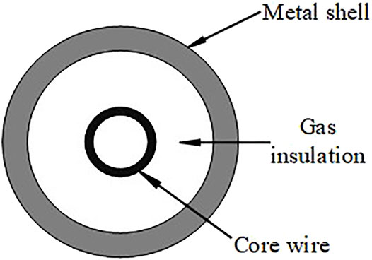
The common geometry of the high-voltage GIL is shown in Figure 1. GIL’s internal core wires, as the main carrier of electric energy transmission, are made of aluminum alloy with high conductivity, to improve the transmission efficiency and reduce transmission loss. What is more, the internal core wire of GIL is designed to be hollow in order to reduce cost, considering the skin effect of AC transmission. The metal shells of GIL, which is also made of aluminum alloy, adopt the same coaxial layout structure as that of the inner core wires of GIL. Furthermore, the core wires can be insulated from the metal shells with the SF6 high-voltage insulation gas filled between the core wire and the shell.
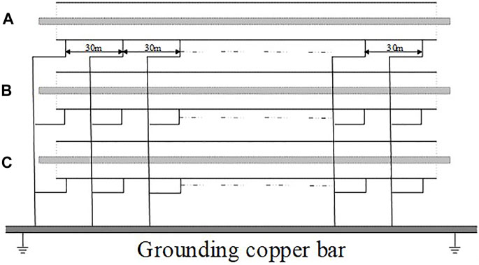
In different applications, GIL will adopt different laying methods. At present, there are mainly three kinds of laying methods: overhead laying, direct burying laying, and tunnel laying. The common laying method of the GIL line is tunnel laying, which has been applied in the Sutong GIL comprehensive pipe gallery project as a case analysis in this paper. The metal shell of GIL will be grounded in order to realize the electromagnetic shielding of the core wire and reduce the induced potential on the metal shell of GIL for the safety of personnel and equipment. In the Sutong GIL comprehensive pipe gallery project, the grounding copper bar is installed along the GIL, the three-phase metal shell is connected with the copper bar with the grounding wire every other 30 m, and the head and end of the grounding copper bar are grounded. Figure 2 shows the schematic diagram of the GIL shell grounding mode in this project.
The transmission line equation of the high-voltage GIL line is shown in (1):
where V and I are respectively the voltage and current vector matrices of each conductive layer of the three-phase GIL and Z and Y are respectively the impedance and admittance parameter matrices of the three-phase GIL. When the grounding parameters that are seen as the current return paths are taken into the GIL parameters, all of the V, I, Z, and Y matrices are the seventh-order matrices, and the voltage and current matrices are shown in (2) and (3).
2.2 Analysis of the GIL Impedance Parameter Matrix
There will exist electromagnetic coupling among the core wire, the metal shell, and the grounding copper bar when the AC current flows through the GIL core wire, which arouses the load current through the core wire and the induced current through the metal shell and the copper bar. Taking the phase I as an example, the equations of the voltage in the transmission line of the GIL core wire and the metal shell are shown in (4) and (5):
where
where
In accordance with (4), (5), and (6), the electromagnetic coupling relationships of the phases and the copper bar of GIL are sorted according to the sequence of the core wire, the metal shell, and the copper bar, and the matrix of the equations of the voltage in the transmission line of GIL is obtained, as shown in (7).
2.3 Analysis of the GIL Admittance Parameter Matrix
There will exist electrostatic coupling among the core wire, the metal shell, and the grounding copper bar when the AC current flows through the GIL core wire. The relationships among current change, admittance and voltage of the core wire, the metal shell, and the copper bar of each phase are listed, as shown in (8):
where
Equation (8) is arranged according to the voltage and current of the core wire, the metal shell, and the copper bar, as shown in (9).
In accordance with (9), the electromagnetic coupling relationships of the phases and the copper bar of GIL are sorted according to the sequence of the core wire, the metal shell, and the copper bar, and the matrix of the equations of the current in high-voltage GIL transmission line is obtained, as shown in (10):
where
Taking the core wire and the metal shell of the phase A as an example, the admittances in (10) can be expressed as follows:
It can be seen from (7) and (10) that the impedance matrix and admittance matrix of GIL including the copper bar are 7 × 7 matrices. The above impedance and admittance matrices accurately reflect the electrical characteristics per unit length of the AC GIL line.
3 Calculation of Equivalent Parameters of the High-Voltage GIL Core Wire
The core wire of the high-voltage GIL is used as the carrier of power transmission, and the voltage and current on both sides of the line can be measured directly. However, metal shells and grounding copper bar are generally not installed with voltage and current measuring devices. In addition, it is hoped that only the core wire parameters, instead of the complex impedance and admittance parameter matrices including metal shell and grounding copper bar, be used for calculation in the short-circuit current calculation and protection setting of power system. Therefore, the following part studies the method of eliminating the mutual inductance and capacitance among the core wire, the metal shell, and the grounding copper bar. Thus, the calculation method of the equivalent parameters of the GIL core wire considering the coupling effect among the core wire, the shell, and the copper bar can be obtained so that the seventh-order core wire parameter matrix can be transformed into a third-order core wire parameter matrix.
3.1 Calculation of the GIL Core Wire Equivalent Impedance Matrix
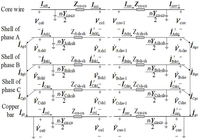
For the GIL model in Figure 2, since the metal shell of GIL is connected with the copper bar every other 30 m, the GIL line can be divided into n sections every other 30 m. The length of GIL line is usually within several kilometers in practical engineering, due to which the centralized equivalent of line admittance parameters has little influence on the parameter characteristics of the whole section; thus, the admittance of the GIL line is concentrated at both ends of the GIL line. At the same time, the three-phase shells at the head and the end nodes, which are directly grounded, are respectively connected with the head and the end of the copper bar. Therefore, the equivalent circuit of the first and last GIL can be obtained, as shown in Figure 3.
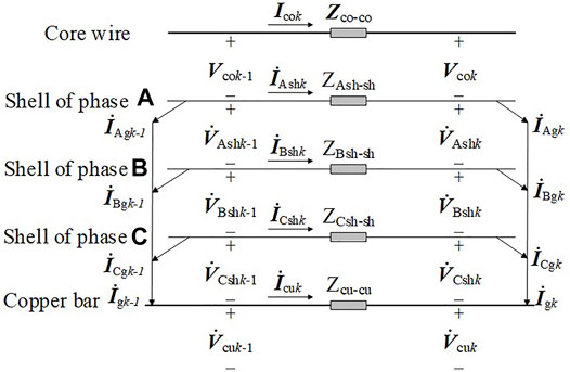
Since the admittance of the GIL line is equivalent to those at both ends of the line, the i section in the middle (i = 2, 3, … ) can be made as the equivalent circuit of GIL according to the connection mode of the GIL shell and the copper bar, which is shown in Figure 4.
In each of the equivalent circuits of GIL,
where
By adding the electrical relations of the GIL from section 1 to section n in turn, the relationship among the voltage change; the impedance; and the current of the whole core wire, the shell, and the copper bar of the whole line of each phase can be obtained as shown in (13).
Since the three-phase shell at both ends of GIL is grounded by the copper bar and the voltage at both ends of the shell and the copper bar is 0, there exists the first boundary condition, which is shown as (14).
According to the equivalent circuit diagram, a part of the current between the adjacent sections on the shell flows to the copper bar through the connecting wire, which is shown as (15).
where
The current on the connecting line will flow into the copper bar, as shown in (17).
where
Equations (15) and (17) constitute the second boundary condition, as shown in (19).
By substituting the first boundary condition and the second boundary condition into the impedance matrix equation of the core wire, namely, put (14) and (19) into (13), the following results can be obtained, as shown in (20):
where
where
In (20), according to the equation of the metal shell and the copper bar, the matrix of the equivalent impedance equation of the core wire can be obtained by eliminating
Thus, the equivalent impedance parameter matrix of each section of the core wire is shown in (24):
where each impedance matrix in (24) is obtained by dividing the impedance matrix in (7), and the specific dividing rules are shown in (12). According to the knowledge of matrix operations, if the matrices
The matrices
where the matrix T is a phase sequence transformation matrix, as shown in (26); besides,
Next, the matrices
Next, taking the matrix
where
Similarly, the matrices
It can be seen that the equivalent impedance parameter matrix
3.2 Calculation of the GIL Core Wire Equivalent Admittance Matrix
The admittance of the GIL line is concentrated on both sides of the GIL line in approximate calculation in this paper, and the relationships among the current change; the admittance; and the voltage of the core wire, the shell, and the copper bar of each GIL phase of section 1 and section n are respectively written in (30) and (31):
where the definitions of
Equation (14) can be introduced into (30) and (31) by substituting the first boundary condition into the impedance matrix equation of the core wire; furthermore, (32) and (33) can be then obtained.
It can be seen from (32) and (33) that the core wire capacitance current of the GIL line after the centralized equivalence is related to the core wire admittance and the core wire voltage but has nothing to do with the current and the voltage on the metal shell and the grounding copper bar. Therefore, the equivalent admittance equations of the core wire are the matrix equations in the first lines of (32) and (33), as shown in (34).
It can be seen from (34) that the metal shell and the grounding copper bar have no effect on the core wire admittance parameters, and then, the core wire equivalent admittance parameter matrix is shown in (35).
It can be seen that the equivalent admittance parameter matrix
4 Simulation Verification of Equivalent Parameter Calculation Method for the High-Voltage GIL Core Wire
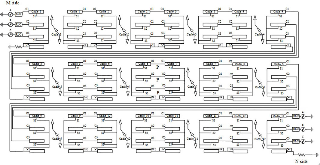
The PSCAD simulation software is used to verify the calculation method in this paper. The shell is grounded with the copper bar every other 30 m in the Sutong UHV transmission project. Thus, the high-voltage GIL line model, built with the shell being grounded by the copper bar every other 30 m, is divided into 200 sections and has a total length of 6 km in the PSCAD. The simulation model that has 200-section GIL is too large, so the simplified 12-section simulation model is used to represent the 200-section GIL simulation model, as shown in Figure 5. Then, the general structural parameters of the high-voltage GIL are shown in Table 1, with GIL horizontal layout of each phase. The general structural parameters of the copper bar are shown in Table 2. At the same time, GIL and grounding copper bar are arranged horizontally. According to the geometric parameters of GIL and grounding copper bar, the horizontal spacing between GIL phases and grounding copper bar is 2 m. That is, if the position of phase A is taken as the reference origin, the horizontal distances of the axis of phase B, the axis of phase C, and the axis of grounding copper bar from the axis of phase A are 2, 4, and 6 m, respectively.
In PSCAD, the unit length impedance matrix and the unit length core wire block admittance matrix of the GIL line at the power frequency of 50 Hz are generated by using the line constants program, and the partial block impedance matrix is obtained after phase sequence decoupling. The matrices
Similarly, according to (35) and the block admittance matrix parameters per unit length of the core wire of the GIL line generated by the line constants program at the power frequency of 50 Hz, the equivalent admittance parameter matrix per unit length of the GIL core wire can be obtained as follows:
The core wire equivalent parameter matrices
The three-phase symmetrical positive sequence, negative sequence, and zero sequence power supplies are added at both ends of the actual GIL parameter model and the GIL equivalent parameter model. The power supply parameters are shown in Table 3.
According to the power supply parameters of both sides given in Table 3, the waveform comparison diagrams of the N side three-phase currents respectively under the positive sequence, the negative sequence, and the zero sequence power supplies can be obtained, which is shown in Figure 7. The solid line and the dotted line respectively represent the current waveform of the GIL equivalent parameter model and the actual GIL model on the N side.
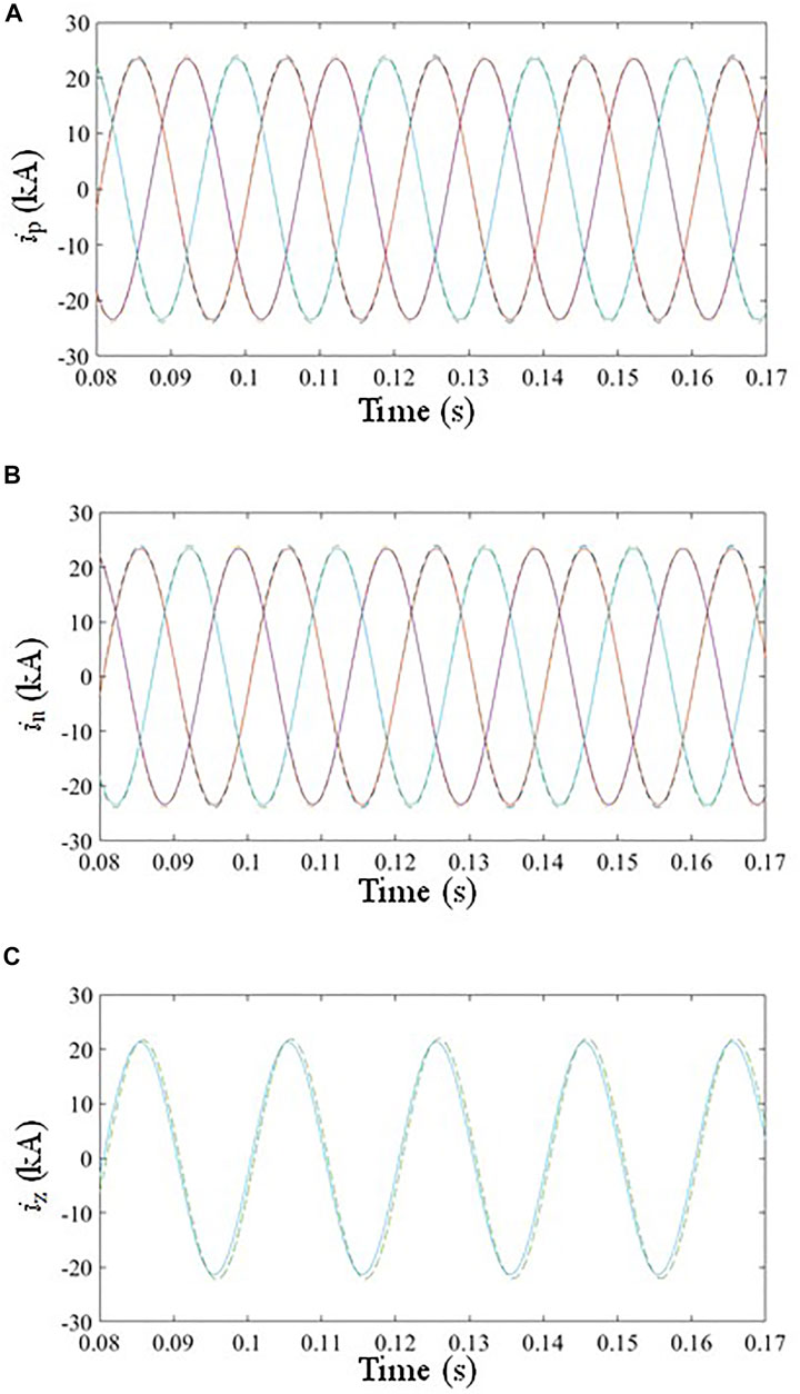
FIGURE 7. Three-phase current waveform on the N side. (A) Positive sequence current of three phases, (B) Negative sequence current of three phases, (C) Zero sequence current of three phases.
It can be found that the amplitude and phase of each sequence quantity are not so far different during stable operation according to the three-phase current waveform on the N side of the actual GIL parameter model and the GIL equivalent parameter model shown in Figure 7, and the specific error data are shown in Table 4.
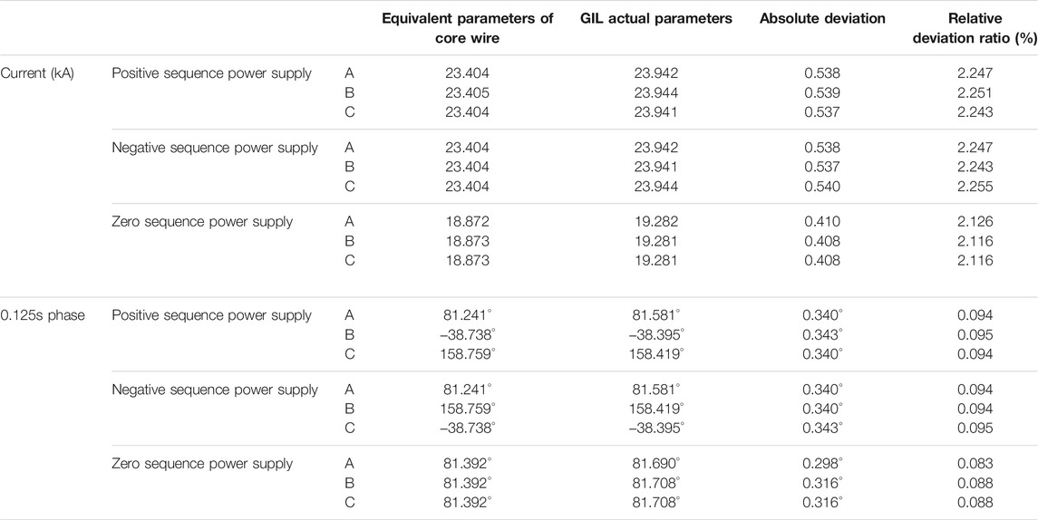
TABLE 4. Comparison table of the three-phase currents on the N side between the equivalent parameter model of the core wire and the actual GIL parameter model.
It is known from Table 4 that the amplitude deviations of the three-phase currents on the N side are all about 2%, and the phase deviations of the three-phase currents are not more than 0.1% whenever under the positive sequence, the negative sequence, or the zero sequence power supplies.
The transient process of the three-phase symmetrical system under fault is simulated to observe whether the GIL equivalent parameter model is consistent with the actual parameter model of GIL in case of fault. In the three-phase symmetrical system, the M side power supply is 520∠0° kV, and the N side power supply is 500∠−45° kV when the faults are respectively set as a single-phase ground fault and a phase-to-phase fault.
When the phase A, the phase B, and the phase C grounding faults with durations of 0.2 s occur successively at the distance of 3 km, namely, at the position P that is shown in the simulation model diagram, on the line at 0.104 s, the three-phase currents on the N side of the two models can be obtained through simulation. The three-phase current waveform on the N side during the phase C grounding fault is shown in Figure 8. The solid line and the dotted line represent the current waveforms respectively of the GIL equivalent parameter model and the GIL reality parameter model on the N side.
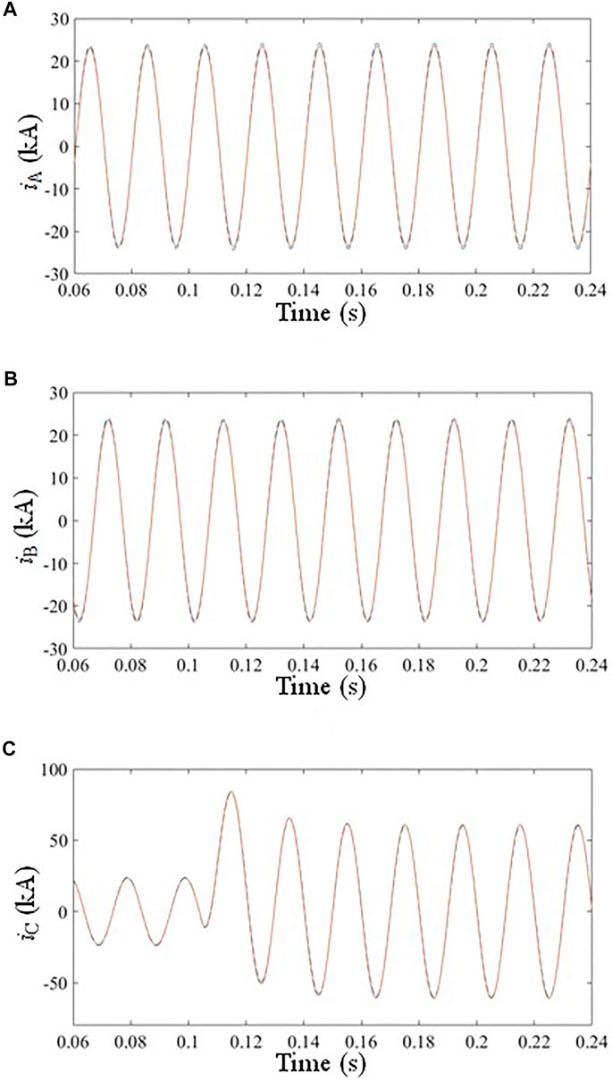
FIGURE 8. Three-phase current waveform on the N side under a phase C grounding fault. (A) Current of phase A, (B) Current of phase B, (C) Current of phase C.
According to the three-phase current waveforms of the actual GIL parameter model and the GIL equivalent parameter model on the N side in case of the phase C grounding fault shown in Figure 8, it can be found that the three-phase current amplitudes and current phases on the N side are not so far different, and the specific maximum error data are shown in Table 5.
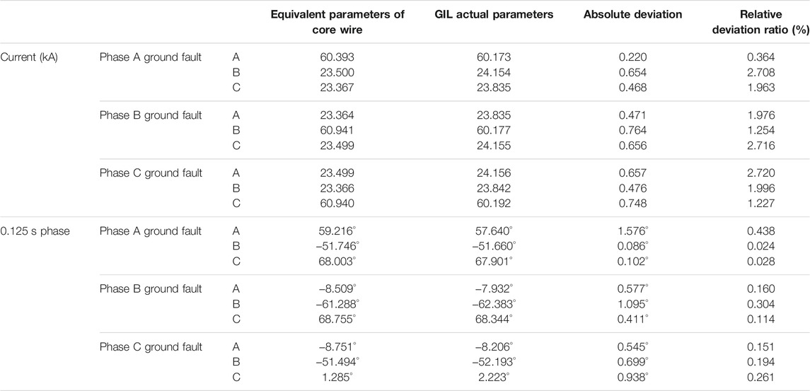
TABLE 5. Comparison table of the three-phase currents on the N side between the equivalent parameter model of the core wire and actual GIL parameter model in case of grounding faults.
When the AB phase-to-phase fault, the BC phase-to-phase fault, and the CA phase-to-phase fault with durations of 0.2 s occur at the distance of 3 km on the line at 0.104 s, namely, the above faults occur at the position P that is shown in the simulation model diagram in the Appendix. The three-phase current waveforms on the N side of the two lines under steady state after the faults occur can be obtained through simulation. The three-phase current waveform on the N side in case of the CA phase-to-phase fault is shown in Figure 9. The solid line and the dotted line represent the GIL equivalent current waveforms, respectively, of the parameter model and the actual GIL parameter model on the N side.
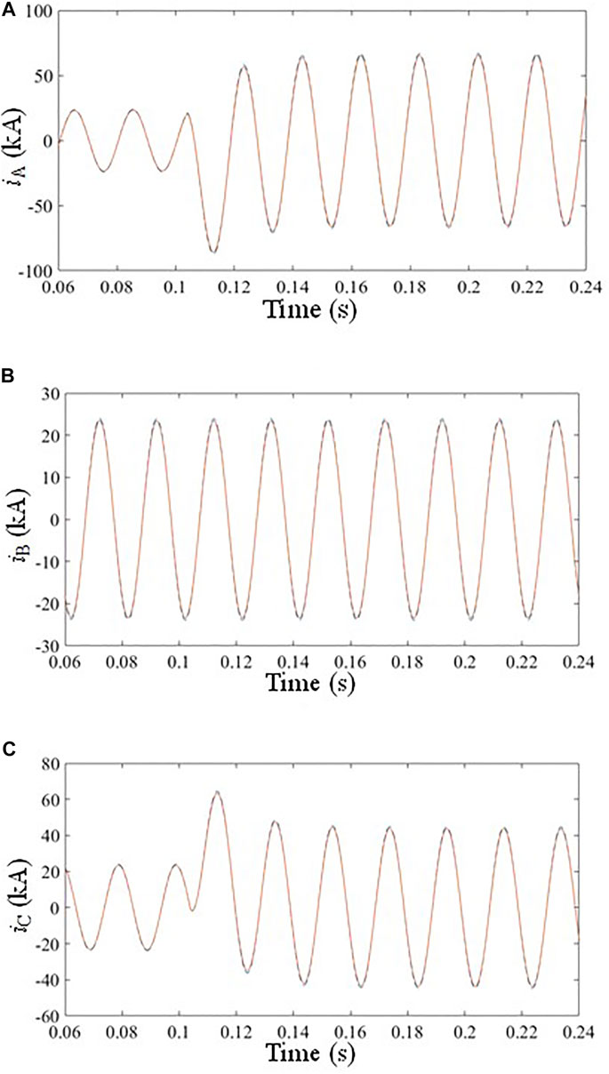
FIGURE 9. Three-phase current waveform on the N side under CA phase-to-phase fault. (A) Current of phase A, (B) Current of phase B, (C) Current of phase C.
According to the three-phase current waveforms of the actual GIL parameter model and the GIL equivalent parameter model on the N side in case of the CA phase-to-phase fault shown in Figure 9, it can be found that the three-phase current amplitude and current phase on the N side are also not so far different, and the specific maximum error data are shown in Table 6.
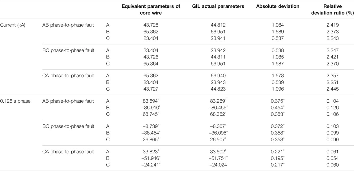
TABLE 6. Comparison table of the three-phase currents on the N side between the equivalent parameter model of the core wire and the actual GIL parameter model in case of phase-to-phase faults.
The simulation models for the three-phase asymmetric power supplies are still shown in Figure 5 and Figure 6. However, the three-phase power supplies on the M side are set as phase A 520∠0° kV, phase B 520∠110° kV, and phase C 520∠220° kV; the three-phase power supplies on the N side are set as phase A 500∠−45° kV, phase B 500∠65° kV, and phase C 500∠175° kV. The maximum error data of the current flows of the three phases, namely, phase A, phase B, and phase C on the N side, are obtained through simulation calculation when the system is in normal operation, which is shown in Table 7.

TABLE 7. Comparison table of the three-phase currents on the N side between the equivalent parameter model of the core wire and the actual GIL parameter model in asymmetric system.
According to Table 8, it can be seen that the line current phasor deviation between the core equivalent parameter model and the actual GIL model is small whether the system is in normal operation or in different types of faults. The maximum transient deviation of the current amplitudes is no more than 3.0%, and the maximum transient deviation of the current phases is no more than 0.5%. In conclusion, the proposed formula for calculating the equivalent parameters of the core wire is of high precision.
5 Conclusion
The high-voltage GIL has a multi-layer conductor structure. When the high-voltage GIL is put into operation, complex electromagnetic and electrostatic coupling effects among the conductor layers will exist. The grounding mode of the copper bar can further aggravate the coupling complexity. In this paper, the parameter matrix of the high-voltage GIL and the boundary conditions of electrical quantities are deeply analyzed for the metal shell grounded through the copper bar. An algorithm is proposed to get the equivalent parameters of the GIL core wire by eliminating the coupling effect of the external conductors by boundary conditions. Thus, the complex seventh-order GIL core wire parameter matrix is transformed into a three-order GIL core wire equivalent parameter matrix. By putting the original complex parameter matrix into the formula, the simplified equivalent core wire parameter matrix can be obtained directly. The significantly simplified core wire parameter matrix can be obtained without complex simulation operation, which improves the speed of short-circuit current calculation and the correlation analysis of high-voltage AC system with GIL.
Data Availability Statement
The raw data supporting the conclusions of this article will be made available by the authors, without undue reservation.
Author Contributions
BL put forward the technical route and guided the writing of the paper. LS completed the specific technical method and paper writing. WW provided technical support for the writing of the paper. BL provided technical support for the writing of the paper. TG provided technical support for the writing of the paper. All authors contributed to the article and approved the submitted version.
Conflict of Interest
Author TG was employed by the The State Grid Tianjin Chengdong Electric Power Supply Company.
The remaining authors declare that the research was conducted in the absence of any commercial or financial relationships that could be construed as a potential conflict of interest.
Publisher’s Note
All claims expressed in this article are solely those of the authors and do not necessarily represent those of their affiliated organizations, or those of the publisher, the editors and the reviewers. Any product that may be evaluated in this article, or claim that may be made by its manufacturer, is not guaranteed or endorsed by the publisher.
References
Benato, R., and Fellin, L. (2004). “Magnetic Field Computation for Gas Insulated Lines Installed in Gallery[C],” in Proceedings of the 39th International Universities Power Engineering Conference (Bristol, UK: UPEC), 2–8.
Benato, R., Carlini, E. M., DiMario, C., Fellin, L., Paolucci, A., and Turri, R. (2005). Gas Insulated Transmission Lines in Railway Galleries. IEEE Trans. Power Deliv. 20 (2), 704–709. doi:10.1109/tpwrd.2005.844308
Benato, R., Di Mario, C., and Koch, H. (2007). High-Capability Applications of Long Gas-Insulated Lines in Structures. IEEE Trans. Power Deliv. 22 (1), 619–626. doi:10.1109/tpwrd.2006.887094
Benato, R., Dughiero, F., Forzan, M., and Paolucci, A. (2002). Proximity Effect and Magnetic Field Calculation in GIL and in Isolated Phase Bus Ducts. IEEE Trans. Magn. 38 (2), 781–784. doi:10.1109/20.996202
Benato, R., and Paolucci, A. (2012). Multiconductor Cell Analysis of Skin Effect in Milliken Type Cables. Electric Power Syst. Res. 90, 99–106. doi:10.1016/j.epsr.2012.04.006
Cheng, J., Zhu, S., Jin, S., and Li, Z. (2019). “Analysis on Electric Field Distortion of Three-phase Tri-post Insulator in 220kV Compact GIL with Metal Defects,” in 2019 IEEE Conference on Electrical Insulation and Dielectric Phenomena (Richland, WA, USA: CEIDP), 251–254. doi:10.1109/ceidp47102.2019.9009697
Goll, F., Witzmann, R., Neumann, C., and Imamovic, D. (2013). “Modeling Techniques for Lightning Overvoltage Analysis Using the Example of Gas Insulated Transmission Lines (GIL)[C],” in Proceeding of the IEEE 1st International Conference on Condition Assessment Techniques in Electrical Systems (Kolkata, India: IEEE CATCON), 6–8.
Gong, A., Wu, Z., Jin, S., Su, X., Liu, P., Peng, Z., et al. (2019). “Transient Overvoltage Simulation Analysis of 1100kV Long Distance GIL,” in 2019 IEEE Conference on Electrical Insulation and Dielectric Phenomena (Richland, WA, USA: CEIDP), 596–599. doi:10.1109/ceidp47102.2019.9009836
Ning, D., Wen-jia, X., Zu-tao, X., Ya-nan, H., Pei-peng, Z., Da-ye, Y., et al. (2020). “Research on Key Technical Problem of System Commissioning of Sutong GIL Utility Tunnel Project,” in 2020 5th Asia Conference on Power and Electrical Engineering (Chengdu, China: ACPEE), 1928–1932. doi:10.1109/acpee48638.2020.9136418
Niu, H., Chen, Z., Zhang, H., Luo, X., Zhuang, X., Li, X., et al. (2020). Multi-Physical Coupling Field Study of 500 kV GIL: Simulation, Characteristics, and Analysis. IEEE Access 8, 131439–131448. doi:10.1109/access.2020.3009694
Piatek, Z., Kusiak, D., and Szczegielniak, T. (2010). “Electromagnetic Field and Impedances of High Current Busducts,” in Proceedings of the 2010 Proceedings of the International Symposium (Wroclaw, Poland: IEEE), 20–22.
Piatek, Z. (2007). Self and Mutual Impedances of a Finite Length Gas-Insulated Transmission Line (GIL). Electric Power Syst. Res. 77, 191–203. doi:10.1016/j.epsr.2006.02.017
Sarajcev, P., Martinac, I., and Radic, Z. (2013). Coupled Electromagnetic and Thermal Analysis of Single-phase Insulated High-Current Busducts and GIL Systems. Ajeee 1, 23–31. doi:10.12691/ajeee-1-2-2
Keywords: GIL, transition resistance, equivalent parameter calculation, core wire, parameter matrix
Citation: Li B, Shi L, Wen W, Li B and Gu T (2022) Research on the Calculation Method of Equivalent Parameters of the Core Wire for the High-Voltage GIL Metal Shell Grounded Through the Copper Bar. Front. Energy Res. 10:813770. doi: 10.3389/fenrg.2022.813770
Received: 12 November 2021; Accepted: 18 January 2022;
Published: 01 March 2022.
Edited by:
Muhammad Wakil Shahzad, Northumbria University, United KingdomReviewed by:
Muhammad Ahmad Jamil, Northumbria University, United KingdomRobert G. Olsen, Washington State University, United States
Copyright © 2022 Li, Shi, Wen, Li and Gu. This is an open-access article distributed under the terms of the Creative Commons Attribution License (CC BY). The use, distribution or reproduction in other forums is permitted, provided the original author(s) and the copyright owner(s) are credited and that the original publication in this journal is cited, in accordance with accepted academic practice. No use, distribution or reproduction is permitted which does not comply with these terms.
*Correspondence: Weijie Wen, d2VpamllLndlbkB0anUuZWR1LmNu
 Botong Li
 Lin Shi
 Weijie Wen1*