 Liangzi Li
 Kaiqi Sun
 Ke-Jun Li
94% of researchers rate our articles as excellent or good
Learn more about the work of our research integrity team to safeguard the quality of each article we publish.
Find out more
ORIGINAL RESEARCH article
Front. Energy Res. , 22 February 2022
Sec. Smart Grids
Volume 10 - 2022 | https://doi.org/10.3389/fenrg.2022.809481
This article is part of the Research Topic Intelligent Operation and Control in Next Generation Urban Power Grid View all 14 articles
With the high proportional renewable energy integration and rapid increase in the DC loads, such as the electric vehicle and distributed energy storage, the DC distribution system becomes a prospective solution for the urban power grid enhancement for its high-efficiency and eco-friendly nature. In most DC distribution systems, power interfaces are applied to connect low-voltage DC (LVDC) distribution systems with multiple medium-voltage (MV) systems in order to improve the operating reliability and economy. Compared to other types of multiports power interfaces, the three-port-isolated modular multilevel converter (I-M2C) has shown many advantages, including low cost, high power density, and low control complexity. However, the I-M2C cannot handle the power imbalance at the bipolar LVDC port like the other MMC-based three-port power interfaces, which limits the operating range and decreases the stability of the I-M2C in bipolar LVDC application. In order to solve the bipolar imbalance problems, a novel balance control method is proposed in this article. The proposed balance control method is based on symmetrical decomposition. By decoupling the MV power control and the LV bipolar power compensation control, the proposed method can eliminate the bipolar voltage deviation under different working conditions. The simulation results prove the validity and good control performance of the proposed method.
With the global-scale urbanization in the past few decades, the urban power grid has met many operating challenges (Sun et al., 2021a; Zhang et al., 2021). In recent years, the DC system has been proved as a prospective selection for urban power grid enhancement (Hakala et al., 2015). Compared to AC power supply technology, DC power supply technology provides many benefits, including asynchronous operation, DC load/source affinity, and larger supply capacity (Sun et al., 2021a; Sun et al., 2021b). For the medium-voltage (MV) level like 10 kV, the MVDC distribution network can increase the efficiency and reliability with large-scale centralized RESs like photovoltaic plants or offshore wind turbines (Zhao et al., 2016). For low voltage (LV) level like ±750V, the LVDC distribution system has many advantages including high power quality, control convenience, and fault ride through capability (Li B et al., 2021; Xiao et al., 2021). With the rapid penetration of renewable energy and the continuous increase of DC loads, such as electric vehicles and distributed energy storage, DC power supply technology will meet unprecedented development opportunities in the urban power grid (Agrawal et al., 2019).
In most of the urban DC application scenarios, the LVDC distribution system is linked to MV distribution systems for increasing the power supply reliability and efficiency. Thus, reliable power interfaces like power converters or solid-state transformers (SSTs) are necessary for the grid integration of an LVDC system (Sun et al., 2021c; Zheng et al., 2021). Unlike classical two-port power interfaces, the MMC-based three-port SSTs can connect the LVDC system to both the MVAC and MVDC systems. Most of the MMC-based SSTs require large quantity of submodule capacitors, which brings high cost and control difficulty (Ma et al., 2020; Ma et al., 2021; Zhou et al., 2021). A novel kind of MMC-based SSTs, isolated MMC (I-M2C), decreases the capacitor number to one by sharing a single capacitor among all the submodules (Liu et al., 2020). I-M2C is proved appropriate for three-port AC/DC hybrid SST application due to its high efficiency and low control complexity.
In order to increase the power capacity, bipolar topology is adopted in many LVDC distribution systems (Rivera et al., 2021). The bipolar topology has a positive pole and a negative pole, and the pole-to-ground voltages are equal. The equivalent line voltage of a bipolar DC system is twice as much as the bus voltage of a unipolar system with the same voltage insulation level. However, the bipolar DC system is required to maintain the balance between the positive side and the negative side.
Bipolar imbalance is caused by the power inequality between the positive pole and the negative pole. In recent years, many research studies have focused on the mitigation of LVDC bipolar imbalance. The LVDC bipolar balance solutions can be classified into two categories: the power balance and the voltage balance (Gu et al., 2016; Lee et al., 2021). The power balance solutions aim at decreasing the bipolar power imbalance by optimization of the system’s inner power flow (Chew et al., 2019; Liao et al., 2021a). The voltage balance method eliminates the bus voltage deviation by regulating the bipolar power inputs from the outer systems with the assist of power interfaces (Cui et al., 2019).
In the previous research, a power interface cannot balance the bipolar voltage unless special topology improvements and corresponding control frames are implemented. Additional transformers or power switches are required to satisfy the power deviation between the positive pole and the negative pole (Li et al., 2018; Li Y et al., 2021; Liao et al., 2021b) (Li Y et al., 2021). Four existing topologies with bipolar voltage balance capability are illustrated in Figures 1A–D. The buck/boost-type voltage balancer and the dual-buck-type voltage balancer in Rivera et al. (2021) regenerate the positive and negative voltages to control the power imbalance. The three-phase rectifier with the utilization of grounding transformer in Li et al. (2018) achieves the bipolar voltage balance by injecting extra zero-sequence current to the LVDC neutral point. The enhanced CLLC converter in Li Y et al. (2021) eliminates the bipolar voltage difference by the regulation of the duty cycle of IGBTs. All the previously existing bipolar schemes add extra voltage balancers in the LVDC systems with extra cost, power loss, and response time. Since the MMC-based three-port SSTs have multiple power submodules, the voltage balance of the LVDC port can be achieved by controlling the LVDC power flows of submodules without adding new power conversion stages, which has been rarely studied in the existing research.
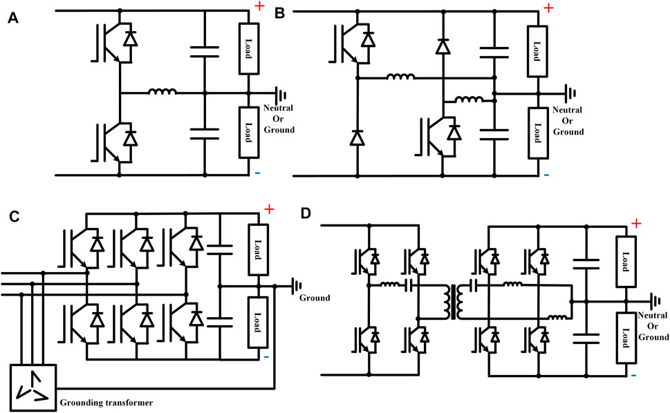
FIGURE 1. (A) Buck/boost type in Rivera et al. (2021). (B) Dual-buck type in Rivera et al. (2021). (C) Utilization of Grounding transformer in Li et al. (2018). (D) Enhanced CLLC with bipolar balance in Li Y et al. (2021).
In this article, a bipolar balancing method for the I-M2C is proposed. The contribution of the proposed method is summarized as follows:
1) A symmetrical wiring topology of the I-M2C is proposed, which does not add extra power devices but only changes the wiring layout.
2) An LVDC bipolar balance control method based on symmetrical decomposition is proposed to control the bipolar differential power without changing the power distribution on the MV side.
3) With the assist of the proposed control method, the I-M2C with the bipolar LVDC port can maintain bus voltage balance under large bipolar power imbalance.
The rest of this article is organized as follows: the I-M2C topology with symmetrical wiring is described in Section 2. The mathematical model of LVDC bipolar balance is analyzed in Section 3. Section 4 introduced the symmetrical balance control method of the hybrid I-M2C. The simulation results are presented in Section 5. The article is concluded in Section 6.
In the urban power system, an isolated modular multilevel converter (I-M2C) is applied as a three-port solid-state transformer between MVDC, MVAC, and LVDC distribution systems, as illustrated in Figure 2. The topology diagram of a three-phase I-M2C is shown in Figure 3A. The three-phase I-M2C has six arms, and each arm is formed by N ISMs. The topology diagram of an upper arm is illustrated in Figure 3B. The submodule of the I-M2C, ISM, can be seen as a phase shift full bridge converter with 8 IGBTs/MOSFETs and a high frequency transformer. As demonstrated in Figure 3A, the ISMs in one arm series are connected at the HV side. In order to achieve the symmetry power balance at the bipolar LVDC port, half of the ISMs are parallelly connected to the positive LVDC link capacitor and the other half are parallelly connected to the negative LVDC link capacitor.
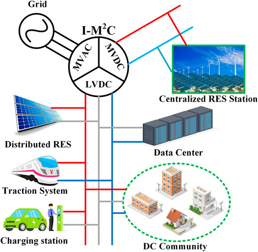
FIGURE 2. Example of the I-M2C in the urban power system.
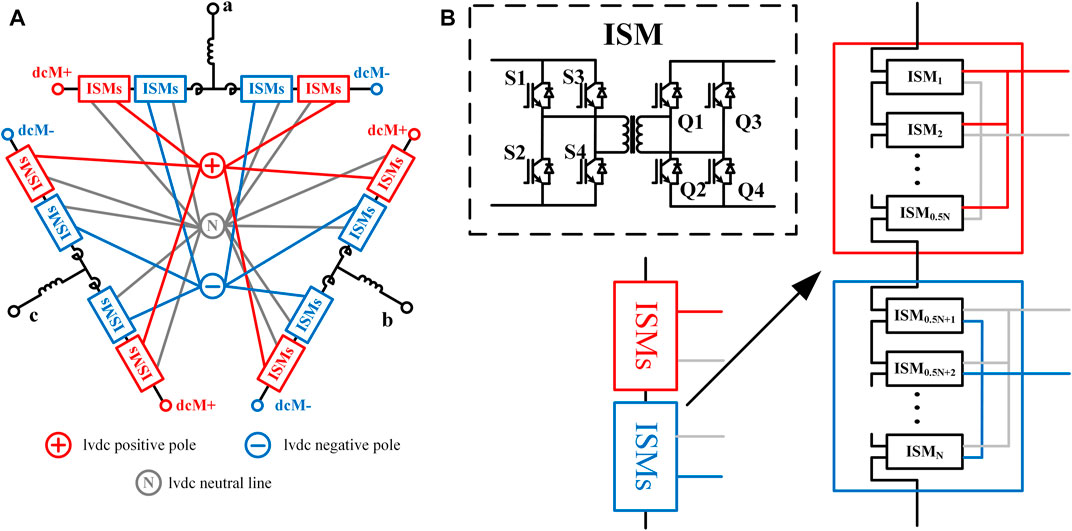
FIGURE 3. (A) Topology diagram of the I-M2C. (B) Topology diagram of an upper arm.
The operation principle of the I-M2C is similar with the carrier wave phase shift modulation control in a classical MMC. The output voltage of an ISM, as illustrated in Figure 3B, is modulated by the duty cycle regulation of the high-frequency waves using the high-frequency transformer, as shown in Figure 4. Two modulation freedoms, one in DC and one in working frequency AC, are utilized in the modulation to generate both the DC voltage and the AC voltage. By the series connected to the ISMs, the arm voltage modulation can be derived as follows:
where uarmju and uarmjl are the upper and lower voltages of the phase unit j, N is the submodule number per arm, k is the ratio of high-frequency ratio, UdcL are the pole-to-pole voltage of the LVDC bipolar port, D is the DC modulation freedom, dj is the AC modulation freedom of phase j, UdcM is the MVDC voltage, and uj is the MVAC voltage of phase unit j.
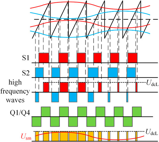
FIGURE 4. Modulation of the ISM output voltage Usm by regulating the duty cycle of the high frequency waves with AC and DC modulation freedoms.
The MVDC power flow is controlled by DC modulation D with the regulation of difference between the MVDC common bus voltage and UdcM. The MVAC power flow is controlled by dj with the control of dq-axis control of the AC phase currents. When the MVAC power is not sent to the MVDC port, the rest active power flows through the ISMs and supply the power consumption of the LVDC system.
Considering the convenience for design and construction, the wiring between the ISMs and the LVDC port is symmetrically connected. As demonstrated in Figure 1B, the top half ISMs in the upper arm and the bottom half in the lower arm are connected to the positive side for each phase unit. Symmetrically, the bottom half ISMs in the upper arm and the top half in the lower arm are linked to the negative side. The proposed symmetry wiring guarantees that the arm voltage modulation should not be affected by the voltage imbalance of the bipolar LVDC system. The modulation of a submodule in the I-M2C can be derived as follows:
where usmpu, usmpu, usmpl, and usmnl are, respectively, the output voltages of the submodules on the upper arms linked to the LVDC-positive pole, on the upper arms linked to the negative pole, on the lower arms linked to the positive pole, on the lower arms linked to the negative pole. UdcLp and UdcLn are, respectively, the positive voltage and negative voltage at the LVDC port. Dp and Dn are the DC modulations for the positive-linked and negative-linked ISMs. djp and djn are the AC modulations of phase j for positive ISMs and negative ISMs.
The arm voltage modulation can be derived as follows:
According to (3), the fundamental AC components of the arm voltages keep symmetrical with the LVDC bipolar voltage difference. Thus, the voltage imbalance at the LVDC port cannot influence the normal operation of the MVDC and MVAC distribution systems. However, the bipolar power imbalance is not controlled by the symmetrical wiring.
In the LVDC distribution system, the bipolar imbalance is shown as the deviation between the positive voltage UdcLp and the negative voltage UdcLn. The intrinsic reason for the voltage imbalance is the power difference between the positive side and the negative side. The mathematical relation between the bipolar voltage deviation and the power imbalance can be obtained as follows:
where CdcL is the capacitance of the LVDC link capacitors. Pconp and Pconn are, respectively, the power consumption of the positive LVDC and the negative LVDC, which are the function of the corresponding voltage.
As demonstrated in (4), the balance control is dependent on the power flow of the positive and negative poles.
As a three-port power electronic transformer (PET), the I-M2C is able to control the active power distribution among the three ports. The active power control is achieved by changing the six-arm voltages’ DC and fundamental AC components. The active power distribution of the I-M2C with a unipolar LVDC port can be obtained as follows:
where IdcM is the MVDC current. uvd, uvq and ivd, ivq are, respectively, the dq-axis components of the three-phase AC source voltages and AC line currents.
Take a positive-linked ISM on the upper arm of phase A as an example, the active power flow through the ISM Psmpua can be obtained as follows:
where θva is the angle between phasor dap and ia.
Extended to the other ISMs and sum, the power flows of the positive pole and the negative pole from the I-M2C can be derived as follows:
where dpd and dpq are dq-axis components of djp, dnd, and dnq are dq-axis components of djn.
The equivalent circuit of the bipolar power flow is illustrated in Figure 5. The arm of the I-M2C can be seen as the DC and AC voltage-controlled voltage source controlled by the bipolar voltages. And the bipolar power flows received from the MVDC and MVAC systems can be equivalent as the DC and AC current-controlled current source controlled by the MVDC current IdcM and MVAC currents ivd and ivq.

FIGURE 5. Equivalent circuit of LVDC bipolar power flows.
It can be seen from Figure 5 that the bipolar power flows are decided by the MVDC/MVAC power and the DC/AC modulations. If the voltage difference is eliminated at steady state, the relationship between the LVDC power and the MVAC/MVDC power can be calculated as follows:
It can be seen from (8), the control of the bipolar power flow lies on the regulation of the DC/AC modulations. However, it can be seen from the variation of DC and AC modulations will change the MVDC and MVAC power as well. The two modulation freedoms should be decomposed into common modulations and differential modulations in order to separate the control of MV power flows and the LVDC bipolar power deviation.
For decoupling the control of MV side power flows and LV side power imbalance, symmetrical decomposition is utilized. As shown in (9), the bipolar elements are divided into common/differential mode elements.
The arm voltage modulation and with common/differential mode can be obtained as follows:
where Ucom and Udif represent the common mode voltage and differential mode voltage of LVDC bipolar voltage, respectively.
The equivalent circuit of the virtual power flow of the common and differential voltage is demonstrated in Figure 6.
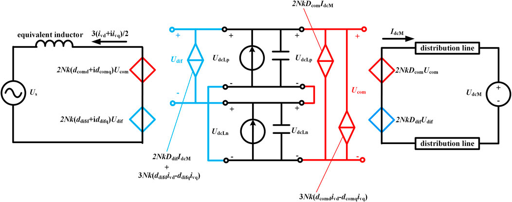
FIGURE 6. Equivalent circuit of the virtual power flows on Ucom and Udif.
The active power distribution based on common/differential mode can be derived as follows:
where dcomd, dcomq, ddifd, and ddifq are the d-axis and q-axis components of AC freedom dj.
According to Figure 6 and (11), in a steady state when Udif = 0, the MVAC/MVAC power is only decided by Ucom and common modulations. In the dynamic state when Udif << Ucom, the influence on MV power flow of common modulations Dcom and djcom is always much larger than the influence of differential modulations. On the other hand, the differential current is directly controlled by Ddif. Therefore, the common modulations can be utilized to control MV power flows independently, while the elimination of Udif can be directly controlled by differential modulations Ddif and djdif.
Based on the mathematical analysis of LVDC bipolar balance, a symmetrical bipolar balance control method is proposed. The common/differential mode decomposition and composition are utilized in the proposed method.
According to (9), the DC modulation freedom can be decomposed into Dcom and Ddif. With the common/differential decomposition, the DC modulation freedom control is divided into common mode voltage control and differential mode voltage control.
As discussed in Section 3.2, the common voltage control is implemented to regulate the total power exchange of the LVDC port with the MVDC port. Double-loop control is applied. The negative feedback control of Ucom is the outer loop, and the inner loop controls the MVDC current IdcM.
The differential voltage controller regulates Ddif to eliminate the voltage deviation between the positive side and the negative side. It can be inferred from Figure 5 that the relation between Udif and Ddif is linearly influenced by the MVDC current IdcM. Therefore, the output of the differential mode controller should be multiplied with IdcM or its positive/negative sign. Taking the coordination with AC modulation freedom control into consideration, the multiply coefficient is set to IdcM.
The double-loop control architecture is also introduced in the differential controllers. After the common/differential controllers calculate Dcom and Ddif, the two DC modulation freedoms are composed to form the direct DC modulation reference waves Dp and Dn for the ISMs. Four PI regulators are used. Theoretically, the transfer functions of Ucom and Udif are mirror symmetrical. Therefore, the inner loop controllers should be numerically equivalent and the outer loop controllers.
Similar to the DC control, dj is decomposed into dcom and ddif. In addition to the common/differential decomposition, the dq-axis decomposition is applied to further divide the AC modulation freedom into dcomd, dcomq, ddifd, and ddifq.
In the classical MMC dq-axis power control theory, the active power is only related to the control of ivd. This inference is valid in the common modulation freedom control. Since the LVDC common voltage Ucom is controlled by the DC control. The AC common control can be occupied to regulate the AC active/reactive power. The classical double-loop dq-axis is utilized for the common control.
When the dq-axis is applied in AC differential control, the inference that ivd independently controls active power is wrong. For the classical MMC dq-axis power control, the AC source voltage usd and usq are utilized. usq is naturally 0 when PLL is successfully achieved and the active power contribution from ivq is 0 as a result. However, the differential control has to utilize the AC components in the arm voltages uvd and uvq. Since uvq is always non-zero, the active power contribution from ivq cannot be neglected.
For analyzing the mathematical relation between the AC currents and the differential control, the phasor diagram of the I-M2C AC voltage in the steady state is illustrated in Figure 7. In a steady state, the bipolar voltage deviation should be eliminated; thus, the common components of uvp and uvn are equal. For the side with more power consumption, its voltage projection on the direction of current iva is required to be larger than the voltage projection on the other side. Therefore, the direction of differential voltage increment uadif should be the same as iva. In the contrary, the phasor voltage of the other side should add an increment to the opposite direction of iva.
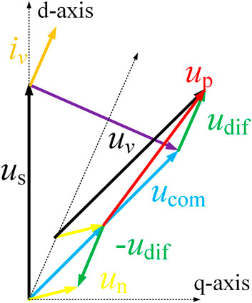
FIGURE 7. Phasor diagram of the I-M2C AC voltage.
Based on the earlier analysis, the dq-decoupling AC differential modulation freedom controller adds two multipliers before output and the multiply coefficients are ivd and ivq.
The diagrams of the DC control and AC differential modulation freedom control are shown in Figure 8. The outer loop of the AC differential controller is the same as the DC controller. Thus, only the inner loop is necessary. The AC controller outputs are composed of djp and djn. According to (2), the reference waves for LVDC positive-connected ISMs should be Dp ± djp. Similarly, Dn ± djn is the modulation reference for LVDC negative-connected ISMs.
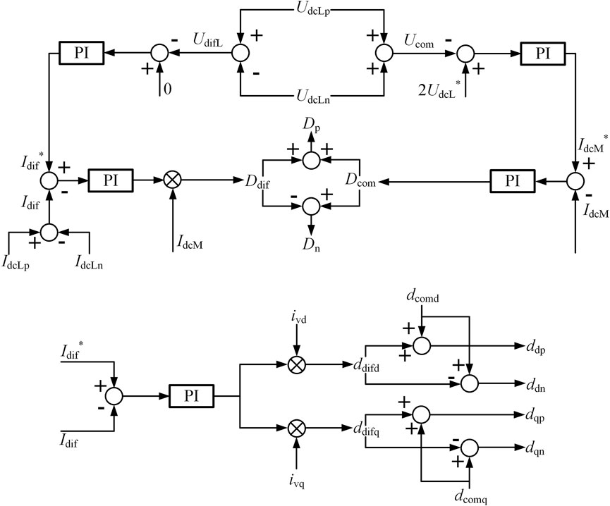
FIGURE 8. Control diagram of AC differential modulation and DC modulation.
As introduced in Section 2, the modulation of the ISMs is based on the duty cycle regulation. Considering the turn on/turn off time and the dead zone of the IGBTs, the modulation range of the submodules is restricted to [0.02, 0.98]. Since the bipolar balance control is dependent on the variation of the modulations, the operation range of the power imbalance is naturally limited within the modulation range.
If the bipolar voltage balance is achieved, the relation between the power imbalance and the modulations can be obtained as (12) according to (11):
The level of power imbalance can be represented by λ=(PdcLp-PdcLn)/PdcL Then (12) can be transformed to the following equation:
It can be deduced from (13) that the range of λ is not only decided by the modulation range but also variable with the ratio of the system power flows PdcM/PdcL and PacM/PdcL. When PacM = 0, djdif = 0, PdcM = PdcL, and Ddif = 0.9, the upper limitation of λ reaches its minimum:
According to (13), the upper limit of λ becomes higher when PdcM/PdcL and PacM/PdcL becomes larger. Not considering the influence of reactive power, if the MVAC power is five times larger than the LVDC power, 100% power loss on one pole is controllable. A linear-approximate function of the relationship between λmax and PacM/PdcL is demonstrated in Figure 9.

FIGURE 9. Relationship between λmax and PacM/PdcL.
Although the controllable imbalance range of the proposed method is limited by the modulation range and the power flow ratio, power imbalances under 38% are always controllable. It should be noticed that even if a high-power high-deviation bipolar imbalance is controlled at the LVDC port, the large current difference between the positive and negative lines will cause the rest busses of the LVDC system to suffer large voltage imbalances. Therefore, a wide range of controllable power imbalance is not necessary for a PET with bipolar balance control capability. On the other hand, the rated capacity of the MVDC/MVAC system is much larger than the eight times of the LVDC system capacity, considering the rated voltage ratio of the MVDC system to the LVDC system. Even if the LVDC system is under full load, the proposed balance control method of the I-M2C is able to stabilize 100% power imbalance under most conditions.
To verify the validity of the proposed method, a detailed simulation of the I-M2C with the bipolar LVDC port was conducted in MATLAB/Simulink. The main parameters of the I-M2C system for simulation are listed in Table 1. The MVDC port of the I-M2C is assumed to be connected to one of the common buses in a ±6kV MVDC distribution system. The MVAC port is linked to a 10-kV MVAC distribution system using a three-phase 50-Hz transformer with 3:5 ratio.
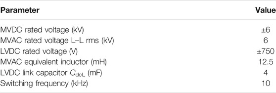
TABLE 1. Parameters of the Simulated I-M2C system.
A bipolar power imbalance event starts at 0.5 s. Before 0.5 s, each LVDC pole carries 100 kW load. The MVAC active power is controlled at 240 kW. At 0.5 s, the LVDC negative load immediately increases 40% up to 140 kW. Naturally, the negative voltage UdcLn falls and UdcLp rises. Then the bipolar balance controller starts to eliminate the bipolar voltage difference by regulating the DC and AC modulations, as shown in Figure 10.
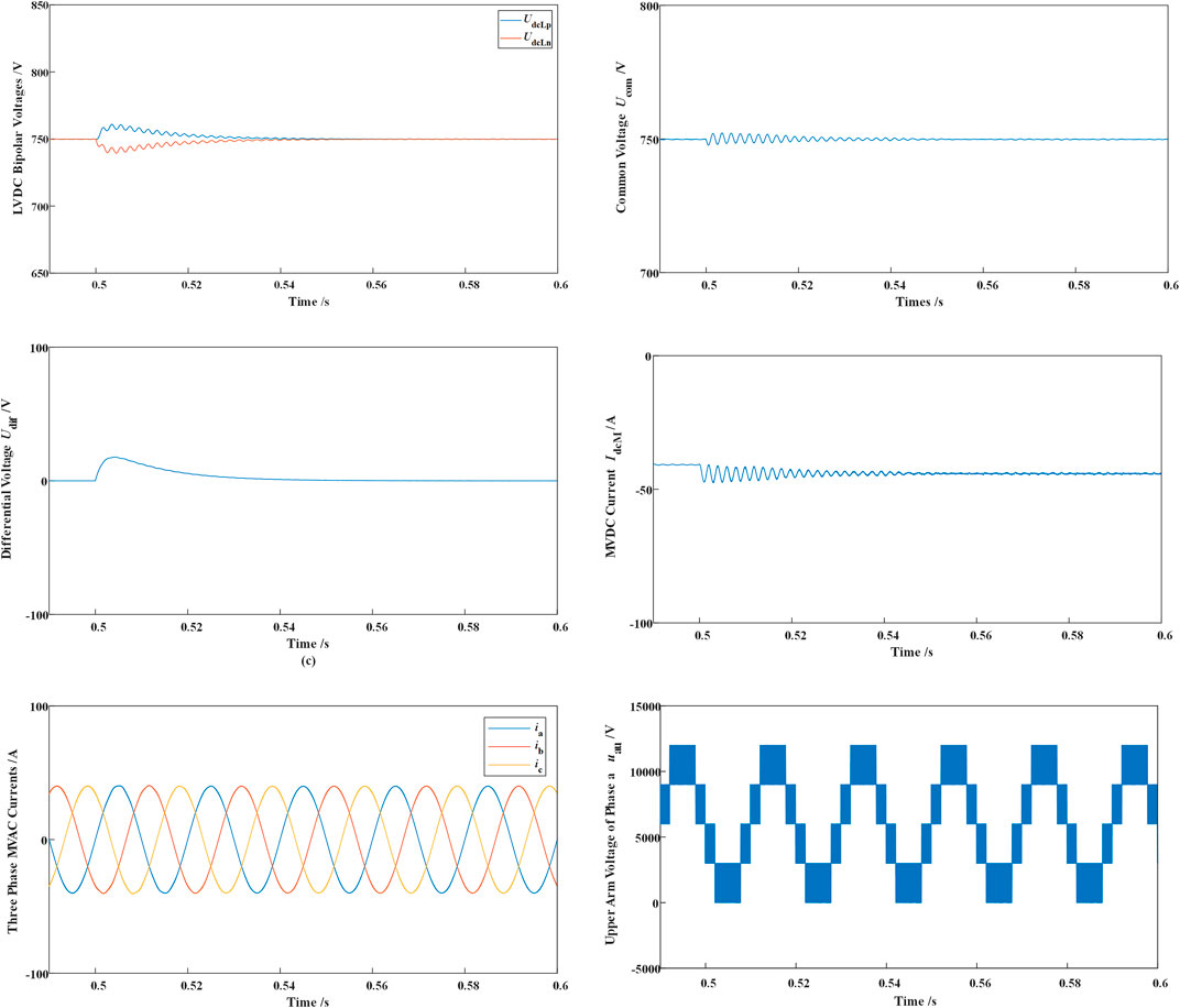
FIGURE 10. Simulation results of a power imbalance event (LVDC bipolar voltages; LVDC common voltage Ucom; LVDC differential voltage Udif; MVDC current IdcM; Three-phase MVAC currents ia, ib, and ic; and upper arm voltage of phase a).
It can be seen from Figure 10 that the voltage difference between UdcLn and UdcLp is controlled to zero nearly 0.06 s after the power imbalance within three MVAC cycles. Since the common voltage is not affected from the power imbalance, the fluctuation of Ucom is only caused by 40 kW rises on the LVDC total load. At nearly 0.504 s, Udif reaches its maximum value 18 V, which is 2.4% of the rated LVDC voltage.
The steady operation of the MVDC and MVAC systems is not disturbed by the power imbalance event. The three-phase MVAC currents are not influenced during the balance control, and the variation of the MVDC current IdcM is controlled by the LVDC common voltage controller.
The modulation regulation during the event is illustrated in Figure 11 the DC modulations are regulated away from the original value 0.5. Since the MVDC system is delivering power to the I-M2C and the negative pole consumes more power, the DC modulation of the submodules connected to the negative pole Dn is higher than Dp. Similarly, the AC modulation of the submodules linked to the negative pole is lower than the positive pole since the MVAC system is receiving power from the I-M2C.
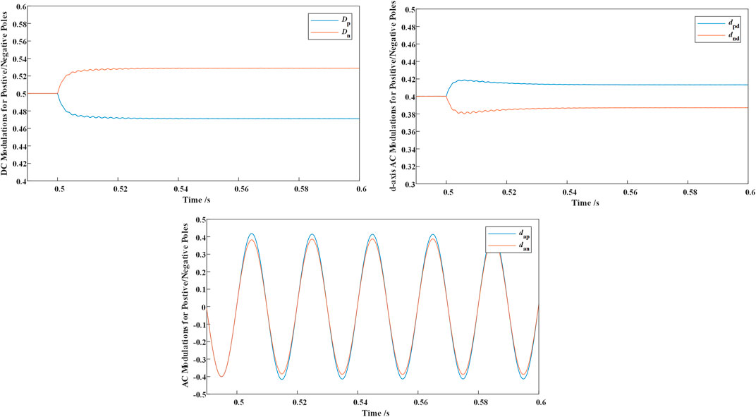
FIGURE 11. Modulation variation during the event (DC modulations Dp and Dn; d-axis AC modulations dpd and dnd; and AC modulations for phase A dap and dan).
As discussed in Section 4.3, the controllable range of LVDC bipolar imbalance is determined by the proportion of MVAC/MVDC power to the LVDC total power. Modulation variations of different cases are listed in Figure 12. The simulation results of power balance control with 0 MVAC power is shown in Fig. 19. It can be seen that the DC modulations vary with different load deviations.
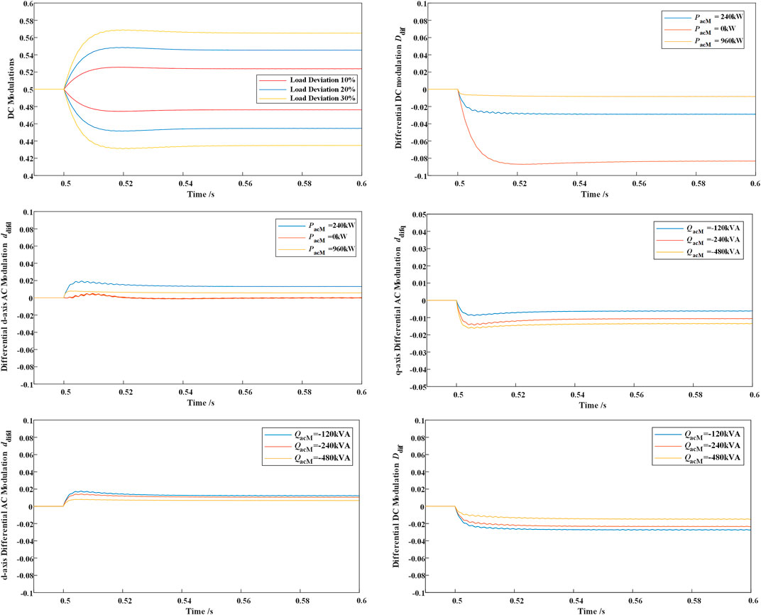
FIGURE 12. Comparison on the modulation in different cases (DC modulations with different load deviation; differential DC modulation Ddif varies with MVAC active power; differential d-axis AC modulation ddifd varies with MVAC active power; differential q-axis AC modulation ddifq varies with MVAC reactive power; differential d-axis AC modulation ddifd varies with MVAC reactive power; and differential DC modulation Ddif varies with MVAC reactive power).
The DC differential modulation Ddif becomes smaller when the MVAC power becomes higher. The d-axis AC differential modulation ddifd becomes smaller when the MVAC power increases from 240 kW to 960 kW, which is caused by the increase in PacM/PdcL.
The effect of MVAC reactive power on the differential modulation regulation is also demonstrated. The simulation results indicate that the reactive power on the MV side can also be utilized to compensate the active power imbalance on the LV side.
According to (4) and (11), the differential power required to achieve voltage balance becomes larger when the LVDC power consumption becomes larger. However, according to (12), the variation of differential is mostly dependent on the ratio of MVAC power and the LVAC power. The simulation of different load conditions is illustrated in Figure 13. It can be seen that the response speed for heavier load is faster, but the maximum voltage difference for lighter load is smaller. It can be shown from Figure 13 that the DC differential modulation varies slightly with different load conditions but with same PacM/PdcL. The result can be compared with the cases where the MVAC power remains the same. It can be referred that any imbalance in the LVDC system can be controlled if the MVAC or MVDC power is much larger than the LVDC power.
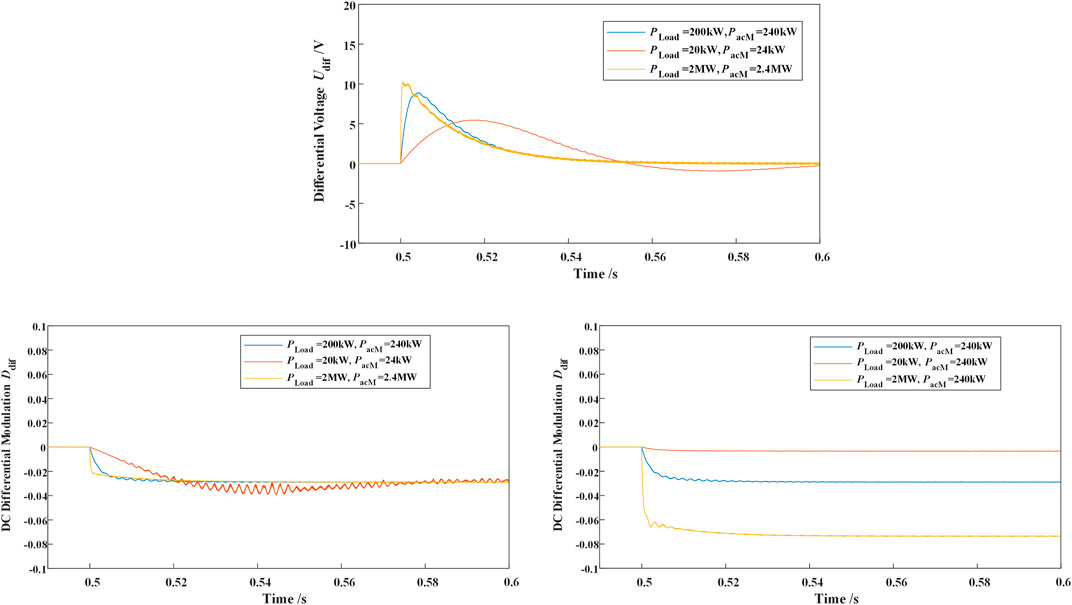
FIGURE 13. Simulation results of bipolar balance with different load conditions.
Four existing LVDC balance topologies, introduced in Li et al. (2018); Rivera et al. (2021) and Li Y et al. (2021), are modeled in MATLAB/Simulink in order to compare with the proposed I-M2C balance method. As shown in Figure 14, the control performances of the buck/boost, dual-buck, and grounding transformer type are relatively worse than those of the proposed method due to the extra usage of capacitors and inductors. The control speed and differential voltage suppression of the enhanced DAB topology in Li Y et al. (2021) is similar to those of the proposed method, which is resulted from the smaller neutral inductors and smaller oscillation capacitors. The detailed control performance comparison is listed in Table 2.
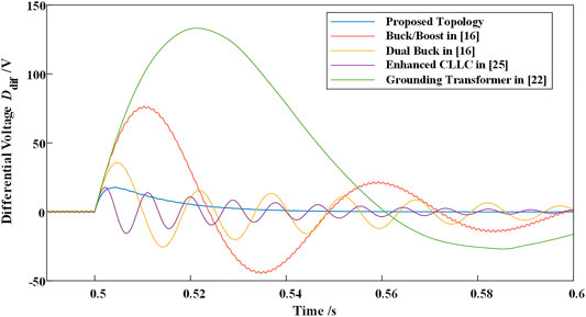
FIGURE 14. Differential Voltage Udif with different LVDC balance topologies.
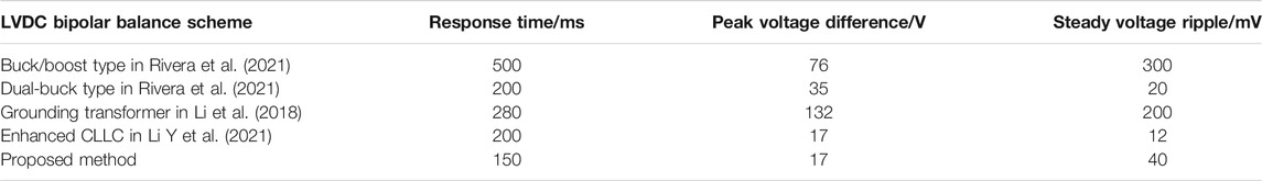
TABLE 2. Comparison results with existing LVDC bipolar schemes.
For the high-efficiency and eco-friendly nature, the LVDC and MVDC distribution systems have become a suitable selection for urban power grid enhancement with the high penetration of renewable energy and DC loads represented by electric vehicles. For achieving reliable interconnecting between the LVDC, MVDC, and MVAC systems, the MMC-based three-port solid-state transformers (SSTs) have become an essential device. Compared to other types of the MMC-based three-port SSTs, the I-M2C is attractive for its reliable operating characteristic and cost-effective performance. However, the I-M2C is not applicable for bipolar LVDC with the existing topology and control methods. In order to maintain the voltage stability and eliminate the bipolar voltage deviation, a novel bipolar balance method for the I-M2C is proposed in this article. Based on the symmetrical decomposition of AC and DC modulation freedoms, the proposed method can generate the differential power between the two poles without changing the power flow on the MV side. The simulation on MATLAB/Simulink verifies the validity and control performance of the proposed balance method. The simulation results indicate that the proposed method can balance the LVDC port from large imbalance disturbance within 200 ms and is adaptive to different working conditions.
The original contributions presented in the study are included in the article/Supplementary Material; further inquiries can be directed to the corresponding author.
Conceptualization: LL, K-JL, and ZL; writing—original draft preparation: LL, K-JL, and KS; writing—review and editing: KS and WW; visualization: WW and LL; supervision: K-JL; and funding acquisition: K-JL. All authors have read and agreed to the published version of the manuscript.
This work was supported by the National Natural Science Foundation of China (U2166202).
The authors declare that the research was conducted in the absence of any commercial or financial relationships that could be construed as a potential conflict of interest.
All claims expressed in this article are solely those of the authors and do not necessarily represent those of their affiliated organizations, or those of the publisher, the editors, and the reviewers. Any product that may be evaluated in this article, or claim that may be made by its manufacturer, is not guaranteed or endorsed by the publisher.
Agrawal, A., Nalamati, C. S., and Gupta, R. (2019). Hybrid DC-AC Zonal Microgrid Enabled by Solid-State Transformer and Centralized ESD Integration. IEEE Trans. Ind. Electron. 66 (11), 9097–9107. doi:10.1109/TIE.2019.2899559
Chew, B. S. H., Xu, Y., and Wu, Q. (2019). Voltage Balancing for Bipolar DC Distribution Grids: A Power Flow Based Binary Integer Multi-Objective Optimization Approach. IEEE Trans. Power Syst. 34 (1), 28–39. doi:10.1109/TPWRS.2018.2866817
Cui, S., Lee, J.-H., Hu, J., De Doncker, R. W., and Sul, S.-K. (2019). A Modular Multilevel Converter with a Zigzag Transformer for Bipolar MVDC Distribution Systems. IEEE Trans. Power Electron. 34 (2), 1038–1043. doi:10.1109/TPEL.2018.2855082
Gu, Y., Li, W., and He, X. (2016). Analysis and Control of Bipolar LVDC Grid with DC Symmetrical Component Method. IEEE Trans. Power Syst. 31 (1), 685–694. doi:10.1109/TPWRS.2015.2403310
Hakala, T., Lähdeaho, T., and Järventausta, P. (2015). Low-Voltage DC Distribution-Utilization Potential in a Large Distribution Network Company. IEEE Trans. Power Deliv. 30 (4), 1694–1701. doi:10.1109/TPWRD.2015.2398199
Lee, J.-O., Kim, Y.-S., and Moon, S.-I. (2021). Current Injection Power Flow Analysis and Optimal Generation Dispatch for Bipolar DC Microgrids. IEEE Trans. Smart Grid 12 (3), 1918–1928. doi:10.1109/TSG.2020.3046733
Li, Y., Junyent-Ferré, A., and Rodriguez-Bernuz, J.-M. (2018). A Three-Phase Active Rectifier Topology for Bipolar DC Distribution. IEEE Trans. Power Electron. 33 (2), 1063–1074. doi:10.1109/TPEL.2017.2681740
Li, Y., Gao, W., Yan, W., Huang, S., Wang, R., Gevorgian, V., et al. (2021). Data-driven Optimal Control Strategy for Virtual Synchronous Generator via Deep Reinforcement Learning Approach. J. Mod. Power Syst. Clean Energ. 9 (4), 919–929. doi:10.35833/MPCE.2020.000267
Li, B., Fu, Q., Mao, S., Zhao, X., Xu, D., Gong, X., et al. (2021). DC/DC Converter for Bipolar LVdc System with Integrated Voltage Balance Capability. IEEE Trans. Power Electron. 36 (5), 5415–5424. doi:10.1109/TPEL.2020.3032417
Liao, J., Zhou, N., Wang, Q., and Chi, Y. (2021). Load-Switching Strategy for Voltage Balancing of Bipolar DC Distribution Networks Based on Optimal Automatic Commutation Algorithm. IEEE Trans. Smart Grid 12 (4), 2966–2979. doi:10.1109/TSG.2021.3057852
Liao, J., Zhou, N., Huang, Y., and Wang, Q. (2021). Decoupling Control for DC Electric Spring-Based Unbalanced Voltage Suppression in a Bipolar DC Distribution System. IEEE Trans. Ind. Electron. 68 (4), 3239–3250. doi:10.1109/TIE.2020.2978714
Liu, C., Liu, C., Cai, G., Ying, H., Zhang, Z., Shan, R., et al. (2020). An Isolated Modular Multilevel Converter (I-M2c) Topology Based on High-Frequency Link (HFL) Concept. IEEE Trans. Power Electron. 35 (2), 1576–1588. doi:10.1109/TPEL.2019.2923355
Ma, D., Chen, W., Shu, L., Qu, X., Zhan, X., and Liu, Z. (2020). A Multiport Power Electronic Transformer Based on Modular Multilevel Converter and Mixed-Frequency Modulation. IEEE Trans. Circuits Syst. 67 (7), 1284–1288. doi:10.1109/TCSII.2019.2931529
Ma, D., Chen, W., Shu, L., Qu, X., and Hou, K. (2021). A MMC-Based Multiport Power Electronic Transformer with Shared Medium-Frequency TransformerIEEE Transactions on Circuits and Systems II: Express Briefs. IEEE Trans. Circuits Syst. 68 (2), 727–731. doi:10.1109/TCSII.2020.3012293
Rivera, S., Lizana, R. F., Kouro, S., Dragicevic, T., and Wu, B. (2021). Bipolar DC Power Conversion: State-Of-The-Art and Emerging Technologies. IEEE J. Emerg. Sel. Top. Power Electron. 9 (2), 1192–1204. doi:10.1109/JESTPE.2020.2980994
Sun, K., Xiao, H., Pan, J., and Liu, Y. (2021). Cross-Seam Hybrid MTDC System for Integration and Delivery of Large-Scale Renewable Energy. J. Mod. Power Syst. Clean Energ. 9, 1352–1362. doi:10.35833/MPCE.2021.000008
Sun, K., Xiao, H., Pan, J., and Liu, Y. (2021). VSC-HVDC Interties for Urban Power Grid Enhancement. IEEE Trans. Power Syst. 36 (5), 4745–4753. doi:10.1109/tpwrs.2021.3067199
Sun, K., Qiu, W., Yao, W., You, S., Yin, H., and Liu, Y. (2021). Frequency Injection Based HVDC Attack-Defense Control via Squeeze-Excitation Double CNN. IEEE Trans. Power Syst. 36 (6), 5305–5316. doi:10.1109/TPWRS.2021.3078770
Xiao, H., Sun, K., Pan, J., Li, Y., and Liu, Y. (2021). Review of Hybrid HVDC Systems Combining Line Communicated Converter and Voltage Source Converter. Int. J. Electr. Power Ener. 129, 106713. doi:10.1016/j.ijepes.2020.106713
Zhang, N., Sun, Q., Wang, J., and Yang, L. (2021). Distributed Adaptive Dual Control via Consensus Algorithm in the Energy Internet. IEEE Trans. Ind. Inf. 17 (7), 4848–4860. doi:10.1109/TII.2020.3031437
Zhao, B., Song, Q., Li, J., Liu, W., Liu, G., and Zhao, Y. (2016). High-Frequency-Link DC Transformer Based on Switched Capacitor for Medium-Voltage DC Power Distribution Application. IEEE Trans. Power Electron. 31 (7), 4766–4777. doi:10.1109/TPEL.2015.2483543
Zheng, L., Kandula, R. P., and Divan, D. (2021). Soft-Switching Solid-State Transformer with Reduced Conduction Loss. IEEE Trans. Power Electron. 36 (5), 5236–5249. doi:10.1109/TPEL.2020.3030795
Keywords: urban power system, DC distribution system, solid-state transformer, isolated modular multilevel converter, bipolar balance
Citation: Li L, Sun K, Liu Z, Wang W and Li K-J (2022) LVDC Bipolar Balance Control of I-M2C in Urban AC/DC Hybrid Distribution System. Front. Energy Res. 10:809481. doi: 10.3389/fenrg.2022.809481
Received: 05 November 2021; Accepted: 27 January 2022;
Published: 22 February 2022.
Edited by:
Yuvaraja Teekaraman, Vrije University Brussel, BelgiumReviewed by:
JIanwen Zhang, Shanghai Jiao Tong University, ChinaCopyright © 2022 Li, Sun, Liu, Wang and Li. This is an open-access article distributed under the terms of the Creative Commons Attribution License (CC BY). The use, distribution or reproduction in other forums is permitted, provided the original author(s) and the copyright owner(s) are credited and that the original publication in this journal is cited, in accordance with accepted academic practice. No use, distribution or reproduction is permitted which does not comply with these terms.
*Correspondence: Ke-Jun Li, bGtqdW5Ac2R1LmVkdS5jbg==
Disclaimer: All claims expressed in this article are solely those of the authors and do not necessarily represent those of their affiliated organizations, or those of the publisher, the editors and the reviewers. Any product that may be evaluated in this article or claim that may be made by its manufacturer is not guaranteed or endorsed by the publisher.
Research integrity at Frontiers
Learn more about the work of our research integrity team to safeguard the quality of each article we publish.