
94% of researchers rate our articles as excellent or good
Learn more about the work of our research integrity team to safeguard the quality of each article we publish.
Find out more
HYPOTHESIS AND THEORY article
Front. Energy Res., 03 February 2022
Sec. Smart Grids
Volume 10 - 2022 | https://doi.org/10.3389/fenrg.2022.803142
This article is part of the Research TopicAdvanced Digital Technologies in Digitalized Smart GridView all 13 articles
 Wu Lifang1*Bai Hao2Zhou Ke1Yuan Zhiyong2Yu Xiaoyong1Lei Jinyong2Zou Yu3Zhang Yuan4
Aiming at the problems that the existing arc suppression cabinet technology cannot adjust the zero sequence voltage flexibly and the control and hardware implementation of active arc suppression equipment based on power electronics are difficult, a new method of voltage arc suppression in the distribution network based on the flexible regulation of the neutral point potential of the new grounding transformer is proposed. From the perspective of the sequence component, the variation law of the neutral point voltage before and after the closing of the tapped grounding branch of the new grounding transformer is analyzed. By selecting the appropriate initial tap position of the tap-to-ground switch, the fault phase voltage is flexibly controlled so that the fault phase voltage is reduced to below the reignition voltage to quickly solve the influence of the single-phase grounding fault, and the risk of non-fault phase insulation breakdown is reduced to ensure the stable operation of the distribution network. According to the ratio of the fault phase current to the zero sequence voltage before and after the gear inputs, whether the arc suppression of the single-phase grounding fault is completed is judged. Compared with power electronic products, the new grounding transformer has the advantages of high reliability, long service life, and low cost and has strong economy and applicability in engineering. The single-phase grounding fault model of the 10kV distribution network is built in the PSCAD/EMTDC simulation environment, and the new method of the distribution network voltage arc suppression based on the flexible regulation of neutral point potential of the new grounding transformer is verified. The simulation results show that the proposed method can effectively reduce the fault phase voltage to achieve the reliable arc suppression of the single-phase grounding fault.
The grounding modes of a neutral point in a power system include direct grounding of the neutral point and non-effective grounding of the neutral point. Among them, neutral non-effective grounding includes non-grounding, arc suppression coil grounding, and high impedance grounding (Li, 2019a). Non-effective grounding method accounts for more than 85% of the voltage levels of 6kV–110 kV in the Chinese power grid (Xue, 2015a). In the long-term power system operation, insulation aging, environmental changes, and other conditions are easy to cause short circuit and other problems. Among them, the proportion of the single-phase short-circuit fault is the largest, accounting for more than 60% of the short-circuit fault types (Choi et al., 2010; Fang, 2017). The single-phase grounding fault is often accompanied by the arc grounding fault (Xiao, 2021), which is harmful to personal and equipment safety for a long time, and the arc grounding fault has complex characteristics such as frequent flameout, small arc current, and strong randomness affected by the environment. Therefore, it is difficult to identify and inhibit the single-phase arc grounding fault, and failing to deal with them in time is easy to cause economic losses and personal safety accidents (Zeng, 2000; Liu, 2016).
The existing arc suppression methods of the distribution network mainly use the neutral point arc suppression coil to compensate the capacitive current of the grounding fault point. According to the compensation object, the arc suppression methods of the distribution network can be divided into the current arc suppression method and voltage arc suppression method, and the current arc suppression law can be subdivided into the passive current arc suppression method and active current arc suppression method. The principle of the passive current arc suppression method is that the neutral point of the power grid and the earth are connected by adjustable inductance. When a grounding fault occurs, the inductive current is output through the adjustable inductance to compensate the capacitive current of the fault point system (Jin, 2010; Elombo et al., 2013; Xue, 2015b; Wang, 2018; Chen, 2020). The principle of active current arc suppression is to measure and calculate the fault current through the transformer and inject a zero sequence current with the same size and opposite direction under the premise of the known fault current so as to realize full current compensation arc suppression (Wang, 2015; Xie, 2015; Guo, 2017; Peng, 2018; Wu, 2018; Xu, 2018; Ze-Yin Zheng, 2020). Based on the principle of the current arc suppression method, the team of Li Jinglu of the Changsha University of Science and Technology developed a set of neutral point dynamic grounding devices to inject the compensation current (Li, 2019b), the team of Guo Moufa of Fuzhou University developed the three-phase cascaded H-bridge current converter to inject the compensation current (You, 2016), and the team of Yang Tingsheng of China Ocean Petroleum International Co., Ltd. developed a power electronic switch turn-regulation arc suppression coil to reduce the fault current (Yang, 2021). For the compensation method of the passive arc coil, some scholars have developed a pre-adjusted arc coil (National Development Reform Commission, 2007), air-gap inductive arc suppression coil, and arc suppression coil composed of three cores and five coils (Cai, 2004; Pang, 2006). However, the essence of the current arc cancellation method needs to obtain the fault current value (Zheng, 2021), while it is difficult to obtain the fault current value accurately in the power system engineering application. At the same time, there are problems; for example, the arc residual current is large (Zhang, 2019), and the arc suppression effect is affected by the control mode and the change of the operation state of the distribution network, so it is not widely promoted.
Aiming at the problems of the current arc suppression methods, voltage arc suppression methods came into being. At present, the voltage arc suppression method mostly used on the market is the fault phase transfer arc suppression technology (Grifflel, 1997; Chen, 2019), and its principle is to set up a grounding branch in the station. When a grounding fault occurs, the short-circuit current of the grounding branch is transferred by short-circuiting the fault phase bus in the station, thereby reducing the fault phase voltage to zero. On the basis of the fault phase transfer technology, the State Grid Corporation puts forward the active intervention arc suppression technology (Wang, 2020). The fault phase transfer technology can alleviate insulation deterioration, improve the accuracy of fault location, and it is simple and easy to operate when operating overvoltage occurs. But when metal grounding fault occurs, the grounding fault current is large (Fan, 2019), and there is a risk of the interphase fault under the condition of phase selection failure (Hänninen and Lehtonen, 1998; Xiang, 2020), so its arc suppression effect will be affected (Yao, 2009).
In view of the above problems, based on the principle of suppressing fault phase voltage re-ignition, a voltage arc suppression method for the distribution network based on flexible regulation of the neutral point potential of the new grounding transformer is proposed. The initial gear size is determined by the ceiling function, and then, the initial gear of the primary side of the new grounding transformer is closed; the tapped grounding branch is divided so that the zero potential is offset, and the zero sequence voltage is adjusted. Then, the ratio of the fault phase current to the zero sequence voltage is used to determine whether the arc suppression is completed so as to achieve rapid and flexible regulation of the fault phase voltage and reliable arc suppression. Furthermore, the single-phase grounding fault model of the 10kV distribution network is built in the PSCAD/EMTDC simulation environment to verify the reliability of the new voltage arc suppression method of the distribution network with a flexible voltage control.
According to the extinguishing mechanism of the grounding arc, the resistance of a grounding medium is inversely proportional to the fault phase voltage (Huang, 2020), and when the maximum re-ignition voltage is less than the recovery speed of the grounding medium resistance, the arc is no longer reignited. According to the long-term operation experience of the distribution grid, the critical value of the maximum reignition voltage is between 0.22 and 0.36 times of the phase voltage in the 10kV distribution network (Yao, 2009).
The principle diagram of voltage arc suppression flexibly controlled by neutral point potential of the grounding transformer is shown in Figure 1.
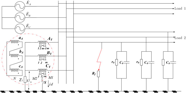
FIGURE 1. Principle diagram of voltage arc suppression with flexible control of neutral point potential of the grounding transformer.
In Figure 1, it is defined that the tap-to-system side is defined as the
When a single-phase grounding fault occurs, the grounding branch switches of taps with different tap positions are closed, and the phase and amplitude of the zero-sequence voltage change so that the fault phase voltage changes according to different tap positions. The amplitude of the fault phase voltage is determined by the number of turns of windings contained in different tap positions, and the system line voltage remains unchanged in the process of mobilizing taps with different tap positions.
The transformer is a static component, and its positive and negative sequence impedances are equal, ignoring the line loss. The equivalent circuit diagrams of the positive sequence, negative sequence, and zero sequence of the system are drawn as shown in Figure 2. The 1-1′ port corresponds to the grounding transformer and the ground, and the 2-2′ port corresponds to the fault point and the ground.
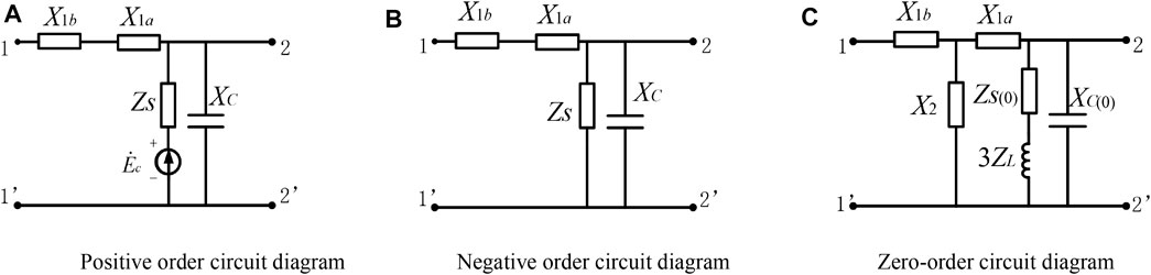
FIGURE 2. Positive, negative, and zero-sequence equivalent circuit diagrams. (A) Positive-order circuit diagram (B) Negative-order circuit diagram (C) Zero-order circuit diagram
In Figure 2,
For the positive order circuit in Figure 2A, it can be described as
For the negative order circuit in Figure 2B, it can be described as
For the zero-order circuit in Figure 2C, it can be described as
The relevant parameters are as follows:
As ZS(0) is far less than 3ZL in Figure 2C, ZS(0) can be ignored, and then, the relevant parameters in Eq. 3 are
When the transformer tap is grounded, there are
According to the positive, negative and zero-sequence equivalent circuit diagrams in Figure 2 and Eqs 10, 11, the equivalent sequence network of the system is obtained, as shown in Figure 3.
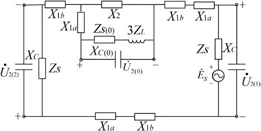
FIGURE 3. Equivalent sequence diagram of the system.
In the positive and negative sequence circuit diagrams, the capacitive reactance
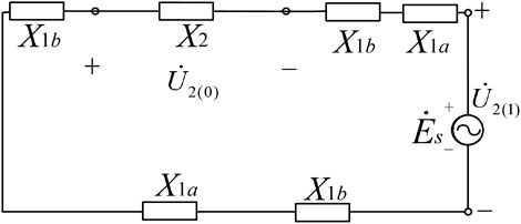
FIGURE 4. Simplified equivalent sequence diagram.
It can be seen from Figure 4 that
Therefore, it is known that after closing the primary side of the new type of the grounding transformer–tapped grounding branch from the perspective of sequence component analysis, the zero potential point offsets making the phase of the zero sequence voltage and phase voltage opposite and reducing the fault phase voltage so as to achieve the arc suppression. The voltage phasors of the system before and after the closing of the tap grounding branch after the single-phase grounding fault occurs are shown in Figure 5.
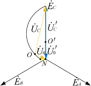
FIGURE 5. Diagram of the system voltage variation before and after closure of the tap earthing branch.
In Figure 5, N is the neutral point of the system,
It can be seen from Figure 4 that the zero-sequence impedance
where x is the ratio of turns of the
It can be seen from Eq. 13 that with the increase of x in the value range, the zero-sequence impedance decreases monotonically. With the continuous increase of gear, the system zero-sequence impedance decreases, resulting in the increase of the loop zero-sequence current and system zero-sequence voltage
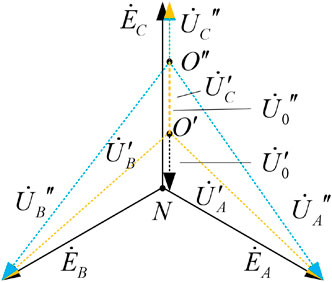
FIGURE 6. Diagram of the system voltage change with the change of the grounding tap of the transformer.
It can be seen from Figure 6 that when a fault occurs, the tap grounding branches of different gears are closed, and the zero potential point shifts and moves in the direction of the phase voltage. Therefore, the zero-sequence voltage changes after closing the tap grounding branches of different gears. So with the increase of gears, the zero potential point gradually increases, and the fault phase voltage decreases.
In order to quickly extinguish the arc in case of a fault, it is necessary to set an appropriate initial gear. Under the initial gear, the critical value of the maximum reburning voltage should be greater than or equal to the fault phase voltage, and the maximum reburning voltage
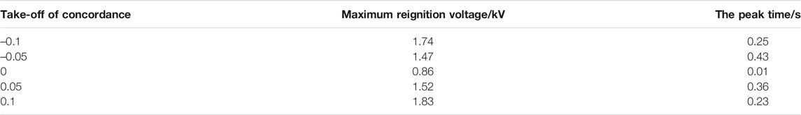
TABLE 1. Maximum reignition voltage under different detuning degrees of the distribution network.
It can be seen from Table 1 that the maximum reignition voltage varies with different detuning degrees. Therefore, in order to determine the initial tap position,
Make the initial gear n; n shall meet
Furthermore, n obtained from Eqs 14, 15
This is because the maximum reburning voltage is different under different detuning degrees. For example, when the detuning degree is 0.1, it can be seen from Table 1 that the maximum reburning voltage is about 0.32 times the fault phase voltage. At this time, after the initial gear is determined according to Eq. 16 for arc suppression, there is still weak arc light leading to reignition, so the initial gear obtained according to Eq. 16 cannot meet all the actual operating conditions on site. Therefore, in order to ensure that arc suppression can be effectively carried out under different operating conditions and the gear adjustment is step-by-step adjustment, round it up by one time along the absolute value through the ceiling function. At this time, the initial gear n is
After determining the initial gear, in order to improve the safe and stable operation ability, one can be added to the initial gear adjustment to ensure the complete arc suppression. Therefore, it is necessary to determine whether the arc is completely eliminated after adjusting the initial gear, that is, whether the fault phase voltage is zero. If it is not zero, one should be added to the actual initial gear to ensure the complete arc suppression. According to the ratio of the fault phase voltage and the fault phase current before and after the tap connection, the judgment method can determine whether the arc suppression is completed.
Since the line voltage of the system remains unchanged before and after the fault, ignoring the loss on the line, the current
where
It can be seen from Eq. 21 that the real part of the fault phase current voltage ratio before and after the initial gear inputs is
The implementation method of the single-phase grounding fault voltage arc suppression in the distribution network is shown in Figure 7. The three-phase voltage or the zero sequence voltage of the distribution network is measured in real time through the measuring elements. When the measurement results show that the 3% phase voltage is less than the change of the zero-sequence voltage or 15% phase voltage is less than the zero-sequence voltage, it is considered that a single-phase grounding fault has occurred in the distribution network. Adjust the gear of the grounding transformer to the initial gear. Then, after a delay of 5 s, judge whether the real part value of the fault phase current voltage ratio before and after the initial gear inputs is equal to
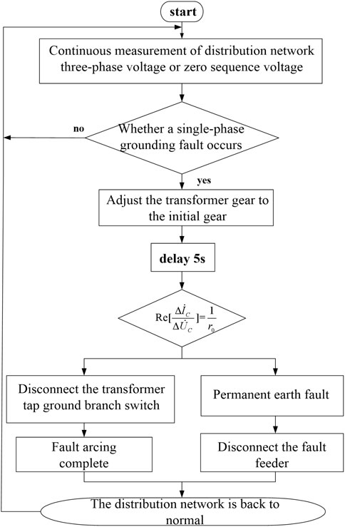
FIGURE 7. Voltage arc suppression flow chart with flexible voltage control.
In the early design scheme of the distribution network, the requirements for transformer capacity are high, resulting in high energy consumption and high actual power cost. At present, the distribution network has innovated the transformer. For the 10 kV distribution network, a section of bus is generally equipped with 12 lines. Using typical distribution network parameters, the system capacitance current is about 100 A, and the transformer capacity
Therefore, using a voltage source with small capacity to make the transformer capacity slightly larger than the load can not only reduce loss and improve power efficiency but also realize the flexible control of the zero-sequence voltage.
In order to verify the effectiveness of the proposed new voltage arc suppression method based on the flexible voltage control of the grounding transformer, a single-phase grounding fault simulation model of the 10 kV distribution network is built in PSCAD/EMTDC software, as shown in Figure 8.
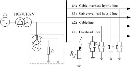
FIGURE 8. Simulation model of voltage arc extinction with flexible voltage control.
Taps at different positions are set at the primary winding side of the transformer. Build various line hybrid models in the PSCAD/EMTDC simulation environment, including the cable line, overhead line, and cable and overhead line hybrid. Their parameters are shown in Table 2.
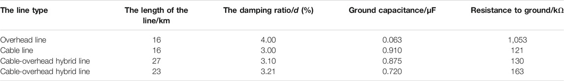
TABLE 2. Circuit parameters.
In the 10 kV distribution network system, the maximum reburning voltage is
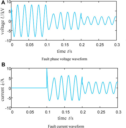
FIGURE 9. Waveforms of the fault voltage and current when tap position is at initial tap position minus 1. (A) Fault phase voltage waveform (B) Fault current waveform.
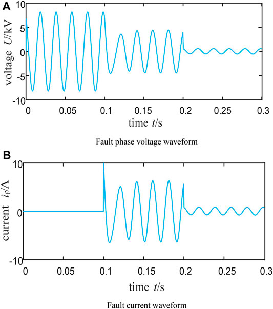
FIGURE 10. Waveforms of the fault voltage and current when the tap is at the initial tap. (A) Fault phase voltage waveform (B) Fault current waveform.
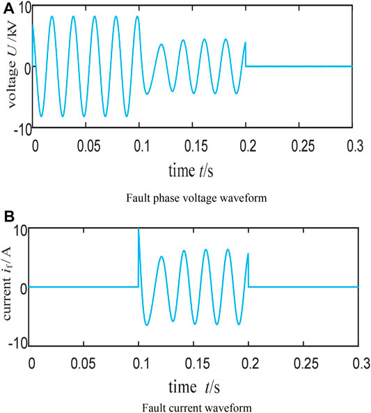
FIGURE 11. Waveforms of the fault voltage and current when tap position is at initial tap position plus 1. (A) Fault phase voltage waveform (B) Fault current waveform.
From Figures 9, 10,11, it can be seen that the single-phase grounding fault occurs in 0.1 s, and the system is asymmetric, resulting in the zero-sequence voltage and fault current. In 0.2 s, adjust the gear. According to the changes of the fault phase voltage and fault current when adjusting different gears, it can be seen that with the adjustment of the gear, the fault phase voltage and fault current decrease accordingly, and when the gear is adjusted to the initial gear, the fault phase voltage is lower than the maximum reignition voltage, which can effectively prevent arc reignition. Record the fault phase voltage and fault current before and after the switch is closed in different gears in Table 3.
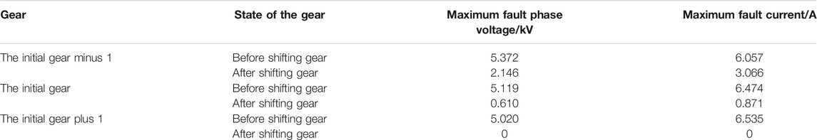
TABLE 3. Comparison of the voltage and current of the fault phase before and after the adjustment of the gear position in different gear positions.
It can be seen from Table 3 that the ratio of the fault phase current to the zero-sequence voltage increases gradually before and after gear adjustment under different gears. When it is below the initial gear, the ratio of the fault phase current to the zero-sequence voltage is about 0.93, and when it is at the initial gear plus 1, the ratio of the fault phase current to the zero-sequence voltage is about 1.3. Therefore, with the gradual increase of the gear, the fault phase voltage becomes smaller and smaller, and the fault arc suppression effect is gradually enhanced. When adjusted to the appropriate gear, the fault phase voltage is less than the arc reburning voltage to prevent fault reburning, fundamentally destroy the reburning conditions, and complete the voltage arc suppression.
Aiming at the problem of the single-phase grounding fault, a new method of voltage arc suppression in the distribution network based on the flexible regulation of neutral point potential of the new grounding transformer is proposed in this study. Taps at different positions are set on the winding of the grounding transformer. By turning on and off taps at different gears, the fault phase voltage is flexibly adjusted. A single-phase grounding fault model of the 10kV distribution network is built in the PSCAD/EMTDC simulation environment. In case of the single-phase grounding fault, turn on the tap to check the change of the fault phase voltage, and then, effectively verify the arc suppression principle of the flexible control voltage proposed in this study. Finally, draw conclusions as follows:
1) From the perspective of a sequence component, a new method of voltage arc suppression in the distribution network based on the flexible regulation of neutral point potential of the new grounding transformer is proposed. By adjusting the initial position of the tap, achieve the arc suppression without measuring the ground parameters. Compared with the current distribution network arc suppression cabinet technology and active arc suppression equipment based on power electronics, zero-sequence voltage regulation is more flexible, control and hardware implementation are more simple, and it has stronger economy and applicability in engineering.
2) Through the selection of the initial tap position by the ceiling function, the zero potential point can be offset after the grounding of the tapped position so that the phase of the power supply voltage of the ground phase is opposite to that of the neutral point voltage, which is beneficial to the arc suppression of the fault. Without directly reducing the fault phase voltage to zero, the non-fault phase voltage does not need to rise to the line voltage, which reduces the risk of the non-fault phase voltage insulation breakdown.
3) Selecting the appropriate initial tap position can reduce the fault phase voltage to below the arc reignition voltage in a short time so as to effectively prevent the arc reignition to realize the rapid arc suppression of the single-phase grounding fault voltage in the distribution network. The arc suppression equipment is of great significance in preventing wildfires, protecting personal safety, and so on. The fault treatment method has theoretical and engineering reference values in the field of grounding fault treatment of the distribution network.
The original contributions presented in the study are included in the article/Supplementary Material, further inquiries can be directed to the corresponding author.
All authors listed have made a substantial, direct, and intellectual contribution to the work and approved it for publication.
This study was funded by Guangxi Power Grid Technology Project (ZBKJXM20190061).
ZY was employed by the Qinzhou Power Supply Bureau of Guangxi Power Grid Co. Ltd. ZHY was employed by the Chongzuo Power Supply Bureau of Guangxi Power Grid Co. Ltd.
The remaining authors declare that the research was conducted in the absence of any commercial or financial relationships that could be construed as a potential conflict of interest.
All claims expressed in this article are solely those of the authors and do not necessarily represent those of their affiliated organizations, or those of the publisher, the editors, and the reviewers. Any product that may be evaluated in this article, or claim that may be made by its manufacturer, is not guaranteed or endorsed by the publisher.
Cai, X. S. (2004). New Resonance Earth System with Magnetic Bias and its protection. Proc. CSEE 4 (6), 44–49. doi:10.13334/j.0258-8013.pcsee.2004.06.009 (in Chinese).
Chen, Y. S. (2019). Effects of Load on Arc-Suppression Method Based on Grounded-Fault Transfer Device. Electr. Meas. Instrumentation 56 (23), 24–30. doi:10.19753/j.issn1001-1390.2019.023.004
Chen, W. D. (2020). Research on Active Arc Elimination Method for Grounding Fault of Distribution Network Based on Current Injection. dissertation/master’s thesis. China University of Mining and Technology.
Choi, Y. J, Choi, M. S, and Lee, S (2010). The Advanced Protection Coordination Scheme using Phase Angle of Zero-Sequence Current in Ungrounded System. Trans. Korean Inst. Electr. Eng. 59 (1), 19-25.
Elombo, A. I., Holtzhausen, J. P., Vermeulen, H. J., Pieterse, P. J., and Vosloo, W. L. (2013). Comparative Evaluation of the Leakage Current and Aging Performance of Htv Sr Insulators of Different Creepage Lengths when Energized by Ac, Dc+ or Dc- in a Severe marine Environment. IEEE Trans. Dielect. Electr. Insul. 20 (2), 421–428. doi:10.1109/tdei.2013.6508743
Fan, S. S. (2019). Arc-Suppression Method Based on Transferring the Residual Current of Single Phase Grounding Fault in Distribution Network. Electr. Meas. Instrumentation 56 (11), 20–25. doi:10.19753/j.issn1001-1390.2019.011.004
Grifflel, D. J. (1997). A New deal for Safety and Quality on MV Networks. IEEE Trans. Power Deliv. 12 (4), 1428–1433.
Guo, M. S. (2017). Flexible Arc-Suppression Potimization Method for Distribution Network Adaptable to Variation of Line Parameters and Load. Automation Electric Power Syst. 41 (8), 138–145. doi:10.7500/AEPS20160621001
Hänninen, S., and Lehtonen, M. (1998). Characteristics of Earth Faults in Electrical Distribution Networks with High Impedance Earthing. Electric Power Syst. Res. 44 (3), 155–161. doi:10.1016/s0378-7796(97)01193-0
Huang, J. S. (2020). Study on Compression Arcing and Lightning Protection of Distribution Network. Insulators and Surge Arresters (01), 111–117. doi:10.16188/j.isa.1003-8337.2020.01.019
Jiale, S. (2010). Study of Zero-Sequence Differential protection for Transformer with Yn/∆ Connection. Power Syst. Prot. Control. 38 (16), 54–61. doi:10.3969/j.issn.1674-3415.2010.16.011 (in Chinese)
Jin, W. S. (2010). A Novel IGBT Based Arc-Suppression Coil Automatic Tuning System. J. Electric Power Sci. Tech. 25 (2), 56–60. doi:10.3969/j.issn.1673-9140.2010.02.011 (in Chinese).
Li, Z. S. (2019a). Multifunctional Safety Earthing Treatment Device for Distribution Network Based on Intelligent Earthing Method of Fault Phase. Insulators and Surge Arresters (01), 116–119. doi:10.16188/j.isa.1003-8337.2019.01.019
Li, Z. S. (2019b). Development and Application of a Complete Set of Neutral Grounding System for Distribution Network Based on the Judgment of Fault. Nature (01), 180–183. doi:10.16188/j.isa.1003-8337.2019.01.030
Liu, B. S. (2016). New Flexible Control System of Full Compensation Single-Phase Ground Fault Fundamental Current. Proc. CSEE 36 (9), 2322–2330. doi:10.13334/j.0258-8013.pcsee.2016.09.002
National Development Reform Commission (2007). PRC.DL/T1057-2007.The Technical Condition of Complete Set of Automatic Tracking Compensation Arc Suppression Coil. China Electric Power Press.
Pang, Q. S. (2006). Design of Air gap Inductance Regulation Arc-Suppression Coil Control System. High Voltage Eng. 32 (4), 5–10. doi:10.13336/j.1003-6520.hve.2006.04.004 (in Chinese)
Peng, S. (2018). Active Arc-Suppression Method of Grounding Fault for Distribution Network Based on Secondary Injection. Power Syst. Prot. Control. 46 (20), 142–149. doi:10.7667/PSPC171503
Wang, Y. S. (2015). Earth Fault Neutralizer Full Compensation Technology and Application. Distribution & Utilization 06, 24–29. doi:10.19421/j.cnki.1006-6357.2015.06.004
Wang, P. S. (2018). Steady-state Modeling and Optimal Design Method of Magnetic Controllable Petersen Coil with Discontinuous Core Structure. Proc. CSEE 38 (18), 5606–5614. doi:10.13334/j.0258-8013.pcsee.170821
Wang, P. S. (2020). Additional Resistance Based Fault Phase Identification Method Suitable for Active Interference Arc Suppression Device. Electric Power Eng. Tech. 39 (04), 180–186.doi:10.12158/j.2096-3203.2020.04.025
Wu, B. S. (2018). A New Type of Arc-Suppression Coil Automatic Tracking Compensation Device. Power Syst. Prot. contro 46 (20), 142–149.doi:10.7667/PSPC171411
Xiang, G. S. (2020). Phase Selection Method for Grounding Faults of Asymmetric Distribution Network Based on Phase Difference. Electr. Meas. Instrumentation 57 (22), 70–76. doi:10.19753/j.issn1001-1390.2020.22.010
Xiao, Z. S. (2021). Single-Phase Grounding Arc Based on Parameter Fitting. Insulators and Surge Arresters (02), 190–197. doi:10.16188/j.isa.1003-8337.2021.02.029
Xie, J. S. (2015). An Active Compensation and Control Method of Asymmetrical Voltage in Non-Solidly Grounded System. Automation Electric Power Syst. 39 (5), 115–121. doi:10.7500/AEPS20140303006
Xu, M. S. (2018). Model Recognition Based Single-Phase Earthed Faulty Line Selection Method of Petersen Coil Grounded System. Power Syst. Prot. Control. 46 (2), 73–78. doi:10.7667/PSPC162117
Xue, Y. S. (2015a). Transient Equivalent Circuit and Transient Analysis of Single-Phase Earth Fault in Arc Suppression Coil Grounded System. Proc. CSEE 35 (22), 5703–5714. doi:10.13334/j.0258-8013.pcsee.2015.22.004
Xue, Y. S. (2015b). Selection Problems of Neutral Grounding Mode in Active Distribution Networks. Automation Electric Power Syst. 39 (13), 129–136. doi:10.7500/AEPS20140717003
Yang, T. S. (2021). Fast Adjustable Arc Suppression Coil Based on Power Electronic Switch. Electr. Meas. Instrumentation 58 (5), 62–69. doi:10.19753/j.issn1001-1390.2021.05.009
You, J. D. (2016). Research of Flexible Arc-Suppression and Fault Line Selection Methods of Earth-Fault in Distribution Systems Based on Cascaded H-Bridge Converter. dissertation/master’s thesis. Fuzhou university.
Zeng, X. S. (2000). New Methods for Control and protection Relay in a Compensated Medium Voltage Distribution Network Based on Injecting Various Frequency Current. Proc. CSEE 20 (1), 30–33. doi:10.13334/j.0258-8013.pcsee.2000.01.008
Ze-Yin Zheng, S. (2020). Flexible Arc-Suppression Method Based on Improved Distributed Commutations Modulation for Distribution Networks. Int. J. Electr. Power Energ. Syst. 116, 105580. ISSN 0142-0615. doi:10.1016/j.ijepes.2019.105580
Zhang, H. S. (2019). Discussion on Earthing Mode of Neutral Point through Arc Suppression Coil in Distribution Network. Insulators and Surge Arresters (03), 87–91. doi:10.16188/j.isa.1003-8337.2019.03.015
Keywords: distribution networks, single-phase grounding fault, neutral point potential, flexible pressure regulating, the voltage arc suppression
Citation: Lifang W, Hao B, Ke Z, Zhiyong Y, Xiaoyong Y, Jinyong L, Yu Z and Yuan Z (2022) Distribution Network Voltage Arc Suppression Method Based on Flexible Regulation of Neutral Point Potential of the New Grounding Transformer. Front. Energy Res. 10:803142. doi: 10.3389/fenrg.2022.803142
Received: 27 October 2021; Accepted: 04 January 2022;
Published: 03 February 2022.
Edited by:
Xiangjun Zeng, Changsha University of Science and Technology, ChinaReviewed by:
Junhua Xu, Guangxi University, ChinaCopyright © 2022 Lifang, Hao, Ke, Zhiyong, Xiaoyong, Jinyong, Yu and Yuan. This is an open-access article distributed under the terms of the Creative Commons Attribution License (CC BY). The use, distribution or reproduction in other forums is permitted, provided the original author(s) and the copyright owner(s) are credited and that the original publication in this journal is cited, in accordance with accepted academic practice. No use, distribution or reproduction is permitted which does not comply with these terms.
*Correspondence: Wu Lifang, ODM3Njc0OTc3QHFxLmNvbQ==
Disclaimer: All claims expressed in this article are solely those of the authors and do not necessarily represent those of their affiliated organizations, or those of the publisher, the editors and the reviewers. Any product that may be evaluated in this article or claim that may be made by its manufacturer is not guaranteed or endorsed by the publisher.
Research integrity at Frontiers
Learn more about the work of our research integrity team to safeguard the quality of each article we publish.