 Run Luo
- 1School of Resource & Environment and Safety Engineering, Cooperative Innovation Center for Nuclear Fuel Cycle Technology and Equipment, University of South China, Hengyang, China
- 2School of Nuclear Engineering, Purdue University, West Lafayette, IN, United States
- 3School of Nuclear Science and Technology, Xi’an Jiaotong University, Xi’an, China
An accelerator driven subcritical system (ADS) is a new nuclear energy system which could not only produce clean energy but also incinerate nuclear waste. In this paper, inherent safety analysis of an ADS is performed with neutronics and thermal-hydraulics coupled code named ARTAP. Five typical accidents are carried out, including the cases of proton beam interruption, transient overpower, reactivity insertion, loss of flow, and loss of heat sink. The transient simulations are performed in the average channel and the hottest channel of the fuel pin in the ADS core. The simulation results for beam interruption show that the highest temperature of the pellet is in the middle of the fuel element in the average channel, while the peak temperature of the cladding is in the top of the fuel element. After the beam is interrupted for 20s, the maximum temperature drops at the fuel center, the cladding inner surface, and the outlet coolant in the hottest channel are 644.46K, 162.27K, and 136.42K respectively. For transient overpower accidents with the increase of beam intensity, the maximum temperature of the fuel and the cladding are below the safety limit. Concerning the reactivity insertion accident, it is found that the ADS has good inherent safety and its margin of criticality safety is large. The calculation results for loss of flow show that the power drop is small due to low sensitivity of the subcritical core to negative reactivity feedback, and the maximum temperature of the cladding reaches 1726K, which means the fuel element would rupture. However, the power and the temperatures of fuel, cladding, and coolant could decrease quickly to the safety level after the proton accelerator is cut off under a loss of flow accident. The results also show that the peak temperature of the cladding is lower than the safety limit under a loss of heat sink accident. The present simulation results reveal that the ADS has a remarkable advantage against severe accidents. It also implies that its inherent safety characteristics could ensure reactor shutdown by cutting off the proton beam after accidents occur.
1 Introduction
Nuclear energy is the hope of sustainable energy growth all over the world. An accelerator driven subcritical system (ADS) is a new nuclear energy system which could not only produce clean energy but also incinerate actinide nuclides and long-lived radioactive fission products (Maschek et al., 2008). The ADS device consists of a subcritical core, a high-energy proton accelerator, and a neutron spallation target, in which the fission process is sustained by a spallation neutron source. Compared with critical fast reactors, ADS have a better performance of nuclear waste transmutation due to a harder neutron spectrum. In recent years, ADS has been attracting more and more attention because of its superior neutronics and safety characteristics (Kumar and Katovsky, 2020). Conceptual designs of three types of eXperimental Accelerator Driven Systems (XADS) have been studied by the European Atomic Energy Community within its fifth framework program (Cinotti et al., 2004), which include a zero-power subcritical facility YALINA, a 80 MW Lead Bismuth Eutectic (LBE) cooled XADS, and a 50 MW multi-purpose hybrid research reactor MYRRHA for high-tech applications. A roadmap for developing an Accelerator Transmutation of Waste (ATW) technology was presented by the United States Department of Energy (DOE) (Van Tuyle et al., 2001), several researchers studied the physics design for using sodium or LBE as coolant of the ATW systems (Hill and Khalil, 2001; Yang and Khalil, 2001). The Japan Atomic Energy Agency (JAEA) has investigated an 800 MW LBE-cooled subcritical reactor with a 1.5 GeV proton accelerator to transmute minor actinides (Sugawara et al., 2018). The research of a HYbrid Power Extraction Reactor (HYPER) has been performed by Korea Atomic Energy Research Institute (KAERI) to produce energy and transmute nuclear waste (Park et al., 2000). The China Lead-based Reactor (CLEAR) and the Chinese initiative Accelerator Driven Subcritical System (CiADS) were proposed by the Chinese Academy of Sciences for the transmutation of nuclear waste and sustainability of nuclear energy development (Wu, 2016; Huang et al., 2021). The conceptual design of a 10 MW LBE-cooled CLEAR has been completed, and a proton accelerator with 650 MHz multicell superconducting radio frequency (SRF) was proposed in the CiADS device.
The components of the ADS system and its operation principle are significantly different from those of traditional nuclear reactor systems. To ensure safe operation of the ADS system, it is necessary to investigate the transient characteristics under accident conditions. Several codes have been developed for the safety analysis of ADS based on a point-kinetics model coupled with thermal and hydraulic feedback effects (Schikorr, 2001; D’Angelo et al., 2003), in which the dynamic behaviors of beam interruptions, loss of flow, and overpower accidents were performed. However, the point-kinetics method may be inaccurate in the case of severe source perturbations involving strong reactivity feedback that produce great flux distortion, which may happen during a serious accident (Eriksson et al., 2005; Rineiski and Maschek, 2005). Therefore, the variation of the spatial shape function with time should be considered in the ADS model. Chen et al. (2003) analyzed some safety characteristics for an LBE-cooled ADS using the extended SIMMER-III code, which is a two-dimensional fluid-dynamics system program coupled with a space-time dependent neutron kinetics model. In addition, Suzuki et al. (2005) investigated the unprotected blockage in a single fuel assembly and severe core-melt accidents with the updated SIMMER-III. The neutronics and thermal-hydraulics coupled simulation program was developed by the FDS team for the design and research of lead or LBE cooled ADS reactors (Wang G. et al., 2015), and three typical transient accidents were simulated with NTC code, such as beam trip and transient overpower condition (Wang Z. et al., 2015). Lu et al. (2016) used the RELAP5 program for the safety analysis on loss of flow accidents and external source transients of a 800 MW ADS with the code modifications of the point-kinetics model and the thermal property package. However, those calculations of safety characteristics mainly investigate the average fuel channel of the ADS assembly under accident conditions, very few studies have taken into account the case of the hottest fuel channel. The assessment of the hot channel factor (HCF) in the ADS core is very important for the quantification of safety margins.
The objective of this research is to analyze the inherent safety characteristics of the LBE-cooled ADS by using a neutronics and thermal-hydraulics coupled simulation code named ARTAP. The developed code consists of a space-time neutron diffusion equation with a spallation neutron source model and a thermal-hydraulics model with a package of thermophysical properties. Five typical accidents are calculated by ARTAP code, which include proton beam interruption, transient overpower, reactivity insertion, loss of flow, and loss of heat sink. In addition, the transient simulations are not only carried out in an average fuel pin of the ADS assembly, but also in the hottest fuel pin. The transient behaviors of the reactor power and the temperatures of the fuel, cladding, and coolant are investigated during the accident sequences.
2 Computational Model and Method
The primary system of the ADS device consists of a subcritical core, a high-energy proton accelerator, and a heavy metal spallation target. The configuration of a typical LBE-cooled ADS is shown in Figure 1. An accelerator proton beam is introduced into the target and then hits the metal target to initiate spallation reaction. As the result of spallation reaction process, neutrons will be supplied to the subcritical reactor core, which serve as an external neutron source to maintain fission chain reactions. The heat produced in the core will be carried out by the coolant of lead bismuth eutectic (LBE). The secondary coolant system is composed of three independent loops which contain three intermediate heat exchangers (IHX). The coolant of the primary loop is high temperature LBE in the IHX and the secondary coolant is an organic diathermic fluid for the Italian ADS system (Cammi et al., 2006).
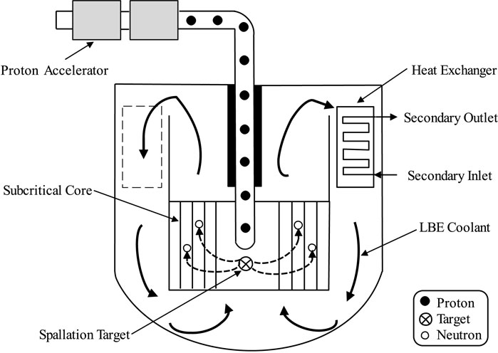
FIGURE 1. Configuration of a typical LBE-cooled ADS.
In this paper, a developed computational code named ARTAP is applied in analysis of the inherent safety characteristics for the LBE-cooled ADS, which comprises of a steady-state analysis module and a transient analysis module. The steady-state analysis module couples a one-dimensional neutron diffusion equation and a thermal-hydraulics single-channel model (Luo et al., 2018). The modeling process of steady-state neutronics is performed in two stages, a low-energy deterministic calculation for the subcritical core and a high-energy Monte Carlo simulation for the spallation neutron source. The single channel model is chosen for the ADS thermal-hydraulics calculation, which includes the heat conduction in the fuel element and the heat transfer from cladding to coolant. According to the power distribution obtained by the neutron diffusion calculation, the thermal-hydraulics analysis is performed, and the obtained temperature distributions of coolant and fuel are selected as the feedback parameters to update the nuclear cross sections. Then the neutron diffusion calculation is carried out to update the power distribution. This coupling iterative process continues until the convergence of power distribution is met. The transient analysis module consists of space-time neutron kinetic equations and thermal-hydraulics dynamic equations. The calculation of transient models is divided into two steps, i.e., the spatial discretization with the finite difference method and the numerical solution of nonlinear time-dependent differential equations with a backward differentiation formulas (BDFs) method (Shampine et al., 1999).
2.1 Space-Time Neutron Diffusion Model
Although the three-dimensional full core multi-physics modeling of a nuclear reactor is an effective way to obtain the key information of the reactor core with high precision, the required data storage space is huge and the running time is quite long. In a few special calculations like performing the reactor control system design, transient safety analysis, or load following study, the detailed radial information of the reactor core is not necessarily needed due to the radially symmetrical layout of fuel assemblies and control rod banks (Song et al., 2016). Thus, a one-dimensional neutron diffusion model in the axial direction will be more preferable when the calculation precision is not reduced.
2.1.1 Space-Time Neutron Kinetics Model
The space and time dependent neutron kinetics model of the ADS reactor is as follows (Duderstadt and Hamilton, 1976):
where va is the average speed of neutron, ϕ is the neutron flux, z is the axial position, t is the time, D is the diffusion coefficient, Σa and Σf are the macroscopic cross section of absorption and fission respectively, ν is neutrons yield per fission, S is the spallation neutron source, β is the total delayed neutron fraction, βj is the delayed neutron fraction of group j, Cj and λj are the delayed neutron precursor concentration and decay constant, respectively.
In the process of the neutron flux calculation, the finite difference method will be used for the discretization in space. This discretization is shown in Figure 2, and the size of each node is Δi. The power iteration method is used to calculate steady-state diffusion equation (Duderstadt and Hamilton, 1976), and the corresponding distribution of neutron flux could be determined by this iterative scheme. After the spatial discretization, neutron kinetics models could be transformed into the normal forms of time-dependent differential Equations which could solved by a backward differentiation formulas (BDFs) method with a scheme of implicit time discretization.
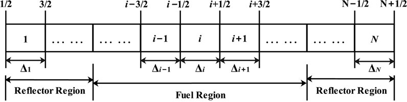
FIGURE 2. Spatial discretization in the axial direction.
2.1.2 Spallation Neutron Source Calculation
The space and energy distributions of the spallation neutrons S (z, t) in the target for the ADS reactor are calculated by a Monte Carlo transport code, which could simulate the interaction between an accelerator proton beam and a metal target (Pelowitz et al., 2005). A model of the spallation target was built by using this code and the neutrons tracked in the spallation target are tallied into an output file, then the distribution of spallation neutrons could be obtained, which are used as the external source for the ADS neutron diffusion calculation. The intensity of the neutron source could be calculated using Equation 3 (Zhou et al., 2014):
where ηp is the number of spallation neutrons released per proton, e is the electric charge on an electron, Ip is the intensity of the proton beam that can be derived by the following formula (Zhou et al., 2014):
where Pf is the total thermal power of the subcritical core, Ef is the averaged energy released per fission, keff is the effective multiplication factor, which is an important concept in reactor physics. When neutron disappearance does not equal neutron regeneration, the keff is introduced to the steady state diffusion equation for the criticality calculation, and the subcriticality 1 − keff could be obtained, which means the distance from a criticality. After external source is added into the subcritical core, the neutron population is perfectly balanced, thus the keff should be eliminated in the ADS steady state calculation.
2.1.3 Macroscopic Cross Section Generation
Taking into account the Doppler effect and the coolant feedback effect, the parameters of macroscopic cross sections (D, Σa and νΣf) are mainly related to fuel temperature Tf and coolant density ρc in Equation 1. The calculation of macroscopic cross sections is performed using a lattice physics code at different temperature points (Luo et al., 2018). Then the values of these parameters D (Tf, ρc), Σa (Tf, ρc) and νΣf (Tf, ρc) could be obtained by a linear interpolation method. Finally, the one-dimensional equivalent parameters are obtained from flux volume weighting in three-dimensional space (Song et al., 2016):
where Mi is the average value of macroscopic cross-section (D, Σa and νΣf) in axial node i, r is the position vector in three-dimensional space, r is the volume of axial node i.
2.2 Thermal-Hydraulics Model
The energy released in the fission reaction in the ADS core and the quantity of heat must be removed from the fuel to the coolant immediately for the safety of the system operation. In this work, a single channel model is performed for the thermal-hydraulics calculation, which includes the heat conduction in fuel element and the heat transfer from cladding to coolant. As we all know, one of the main goals of the thermal-hydraulics core design is to ensure that the core temperatures remain below the damage limit of core components, especially for the fuel pellet and the cladding materials. Therefore, it is significant to obtain the maximum fuel temperature from the analysis of transient behavior of the average and hottest channels in the ADS core.
2.2.1 Heat Conduction in Fuel Elements
In order to obtain the spatial distribution of temperatures of fuel and cladding, the fuel element is divided into K nodes in the axial direction and L nodes in the radial direction, as shown in Figure 3.
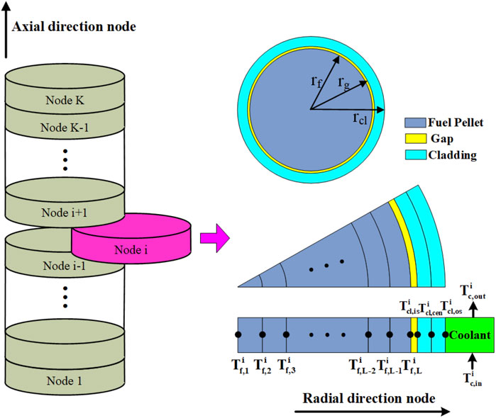
FIGURE 3. Node division in a fuel element.
Since the thickness and thermal resistance of cladding are much smaller than those of fuel pellet, the cladding is only divided into three nodes in the radial direction to obtain its inner surface and outer surface temperatures. Axial heat conduction is ignored because of prevailing radius to length ratios and axisymmetry (Wulff et al., 1985). Therefore, the heat conduction equation for the fuel pellet in the axial node i could be written as:
The boundary conditions of the heat conduction equation for the fuel pellet can be described as:
where
Ignoring the heat generated in the cladding (Schikorr, 2001), we obtain the heat conduction equation for the cladding in the axial node i as:
The boundary conditions of the heat conduction equation for the cladding can be described as:
where
2.2.2 Heat Transfer to Coolant
The heat transfer from cladding to coolant in the ith node along the reactor axis direction can be described by the basic mass and energy conservation equations as (Schikorr, 2001):
where
In fast spectrum ADS designs, heavy liquid metals such as lead (Pb) or lead bismuth eutectic (LBE) are usually adopted as the coolant materials for high heat transfer coefficient and large heat capacity. The fuel assembly of ADS is usually composed of triangular rod bundles, and thus the Ushakov correlation is used to analyze the heat transfer correlation between the heavy liquid metal coolant and the cladding (Pfrang and Struwe, 2007). The heat transfer coefficient between cladding and coolant is calculated by:
where kc is the heat conductivity of the coolant, Dc is the hydraulic equivalent diameter, the Nusselt number Nu in the rod bundles is as follows (Pfrang and Struwe, 2007):
where p/d is the ratio of the pitch of fuel pins to its diameter, Pe is the Peclet number. It is valid for 1.2 < p/d < 2.0, and 1 < Pe < 4,000.
2.2.3 Heat Exchanger Model
The primary coolant flows out of the core and enters the heat exchanger through the ascending channel. The primary coolant then flows down to the lower plenum after its heat is transferred to the organic diathermic fluid on the secondary side. The schematic diagram of primary circuit is shown in Figure 4. The heat transfer models of primary coolant, tube wall, and secondary coolant are as follows (Cammi et al., 2006):
where hp,w is the heat transfer coefficient between the primary coolant and tube wall, hs,w denotes the heat transfer coefficient between the tube wall and secondary coolant.
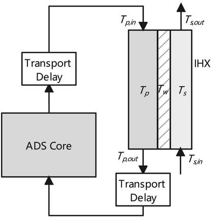
FIGURE 4. Schematic diagram of primary circuit.
2.2.4 Thermophysical Properties of Materials
The package of thermophysical properties of materials were developed to insert into the thermal hydraulic model based on the experimental data and empirical correlation (D’Angelo et al., 2004; Sobolev, 2011). The correlations of the thermophysical properties of coolant, cladding, and fuel are presented in Table 1.
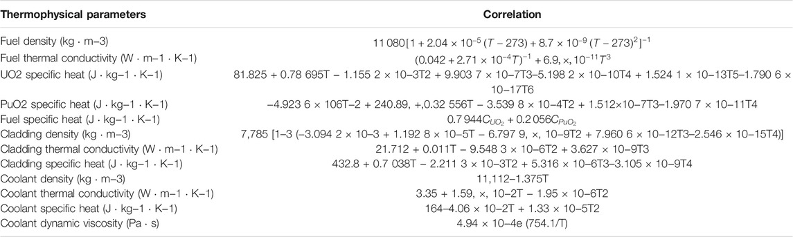
TABLE 1. Thermophysical properties of fuel, cladding and coolant.
2.3 Process of Coupling Calculation
The developed ARTAP code comprises of a steady-state analysis module and a transient analysis module. A flowchart of the neutronics and thermal-hydraulics coupled calculation is shown in Figure 5. After macroscopic cross sections and spallation neutron source are obtained, neutron diffusion equations are solved by the power iteration method. According to the power distribution by the neutronics calculation, the thermal-hydraulics analysis is performed, and the obtained distributions of fuel temperature and coolant density are selected as the feedback parameters to update the nuclear cross sections. Then the neutron diffusion calculation is carried out to update the power distribution again. This coupling iterative process continues until some criterion for convergence is met. The steady-state parameters of reactor neutronics and thermal-hydraulics are provided as initial parameters for dynamic simulation.
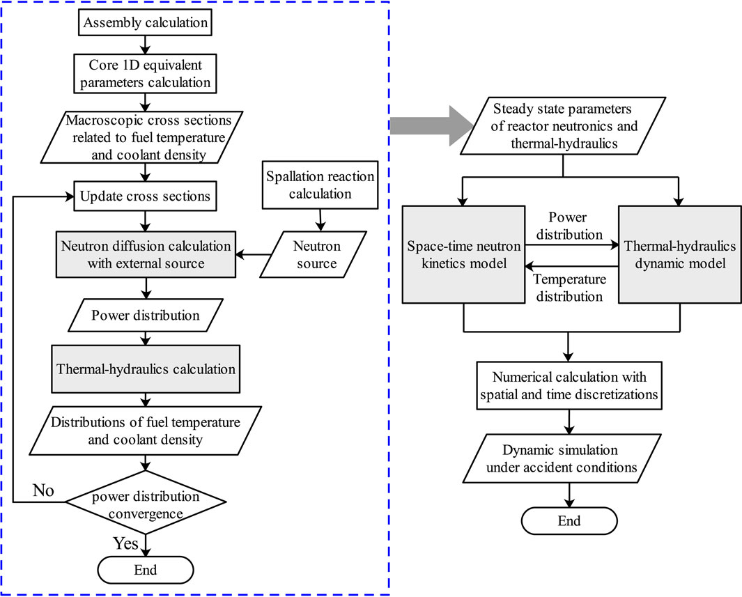
FIGURE 5. Numerical calculation flowchart.
The ARTAP code was verified by comparing its predictions for both steady-state and transient cases of the OECD/NEA benchmark (D’Angelo et al., 2003). The benchmark summarizes a comparative analysis of ten different codes. Three cited codes for the comparison are: TRAC-MOD, SAS4ADS and EXCURS-M, as they represent the range of data scatter in the published results of benchmark report. The results indicate that ARTAP is accurate and efficient to be applied for the ADS safety analysis (Luo et al., 2018).
3 Results and Discussions
The Italian 80 MW XADS reactor was chosen as a typical LBE-cooled ADS to investigate its inherent safety characteristics in this work. The arrangement of assemblies and R–Z view of this reactor are shown in Figure 6 (Luo et al., 2015). The LBE-cooled core is divided into several regions. The inner region consists of 120 hexagonal MOX fuel assemblies with equal dimensions, and the top and bottom of the fuel assemblies are gas plenum, each assembly includes 90 triangle-distributed fuel rods. Dummy assemblies in the outer region mainly contain LBE which is taken as the reflector. The Central channel is designed to introduce proton beam into the spallation neutron target. The outside of core region is filled with LBE coolant, which serve as axial reflector and radial reflector. The main technical design parameters of the reactor are listed in Table 2. In order to study the transient behaviors and their uncertainties under different fuel power density conditions, the transient simulations are performed in the average fuel pin and the hottest fuel pin of the ADS assembly. The linear power density of the hottest fuel pin is 1.4375 times that of the average fuel pin (D’Angelo et al., 2004). Five typical accidents are carried out which include proton beam interruption, transient overpower, reactivity insertion, loss of flow, and loss of heat sink.
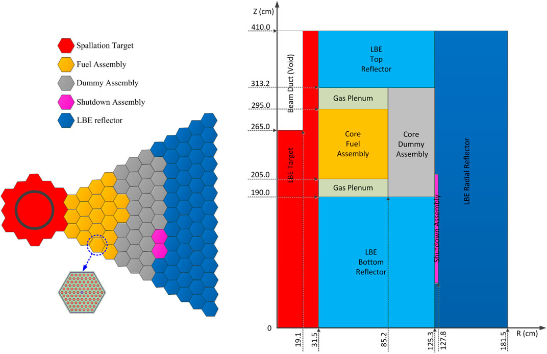
FIGURE 6. Arrangement of assemblies and R–Z view of reactor model.
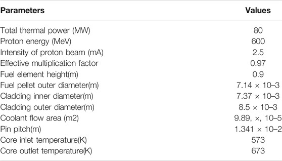
TABLE 2. Main design parameters of the ADS system.
3.1 Beam Interruption Accident
The proton beam in the accelerator plays a very important role in the ADS core. On the one hand, in normal steady-state operation of the ADS system, the high-energy proton beam interacts with the spallation target to generate an external neutron source to maintain the sustainable fission reaction of the subcritical core. On the other hand, the power level could be changed by adjusting the beam intensity during the transient operating conditions, and the external neutron source in the core could be interrupted by quickly cutting off the accelerator beam so as to achieve the emergency shutdown protection under accident conditions. However, the reliability and stability of the accelerator device itself will also affect the safety operation of the ADS system, especially a sudden short-term interruption of accelerator beam would cause transient temperature changes of key materials in the fuel element, and even lead to thermal fatigue damage of the materials. Therefore, it is necessary to analyze the impact of beam trips on the temperature changes of the fuel, cladding, and coolant.
In this work, a beam interruption accident is simulated with ARTAP, in which the accelerator beam suddenly interrupted from the fifth second, and then restored to the initial value at the 15th second. The results of transient responses of the average channel are presented in Figure 7. It can be seen from Figure 7A that the neutron flux density drops sharply at the fifth second because the external neutron source generated by the proton beam and the spallation target disappears instantly, and the value of neutron flux in the middle of the core is greater than those at the top and bottom of the core. The neutron flux quickly declines to a very low value and then slowly decreases due to the production of delayed neutrons in the core and the negative feedback effect of reactivity. After the beam recovers to normal at the 15th second, the external neutron source returns to the initial value, so the neutron flux also rises rapidly and gradually restores to the steady state value. In the process of the proton beam being interrupted for a short time and then recovering, the thermal power firstly drops and then rises rapidly and gradually returns to a steady-state level, the temperatures of the fuel, cladding and coolant also change sharply. The temperature variations at different positions of the fuel centerline is shown in Figure 7B, where the highest fuel temperature is in the midplane. Figure 7C reveals that the temperature of the cladding inner surface declines at a low value and then increases at a steady-state level, and the cladding temperature at the top of the core is the largest. The temperature variation of the coolant is shown in Figure 7D. The outlet coolant temperature (top of the core) changes the most, while the inlet coolant temperature (bottom of the core) changes the least, because there is a certain time lag of the coolant temperature from the heat exchanger outlet to the core inlet. Therefore, the coolant temperature change of the bottom position is slower than those of the middle and top positions.
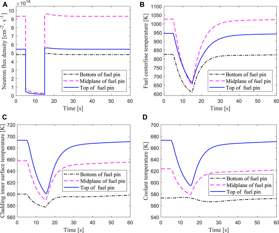
FIGURE 7. Transient responses of the average channel under beam interruption accident for 10 s.
Compared with the average fuel channel, there is also a fuel element with the highest linear power density in the core, which is usually called the hottest fuel channel. In the neutronics and thermal-hydraulics designs of the nuclear reactor, the local peak analysis of the neutron flux and material temperatures in the core should be carried out to ensure the safety operation of the reactor. From the foregoing, it can be seen that the highest fuel temperature is in the middle of the core, while the highest cladding and coolant temperature is in the top of the core. Therefore, it is very important to analyze whether these parameters of the hottest channel exceed the safety limits under accident conditions. In case of the beam interruptions for 10s, 15s, and 20s, the response results of the hottest channel for the normalized thermal power, the fuel temperature in the middle of the fuel element, the cladding surface temperature and coolant temperature in the top of the fuel element are shown in Figure 8. It can be seen that the longer the beam interruption lasts, the lower the value that the power decreases by. Similarly, the longer the beam interruption lasts, the greater the temperatures of the fuel, cladding, and coolant change, and the variations of these parameters are shown in Table 3. When the beam is interrupted for 20s, the maximum temperature drops of the fuel center, the cladding inner surface and the outlet coolant are 644.46K, 162.27K, and 136.42K respectively. The fuel pellet and cladding will not be damaged for a short-term beam interruption accident, but if the proton accelerator could not maintain stable operation, the frequent interruptions may cause thermal fatigue damage of the cladding material, which will affect the life of the ADS core.
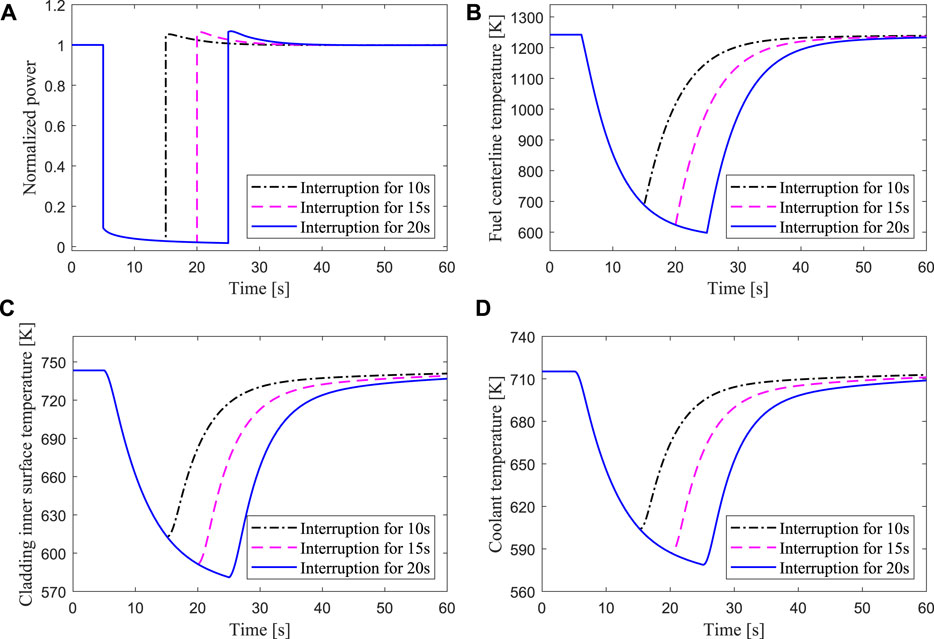
FIGURE 8. Transient responses of the hottest channel under beam interruptions for 10 s, 15 s, 20 s respectively.
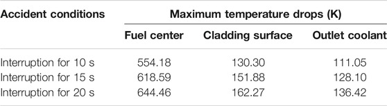
TABLE 3. Temperature variations of the fuel center, cladding surface and outlet coolant in the hottest channel under beam interruptions for 10 s, 15 s, 20 s respectively.
3.2 Transient Overpower Accident
With the operation of the reactor, the consumption of fission materials in the fuel element, and the accumulation of fission products, the effective multiplication factor would gradually decrease. The intensity of the proton beam would be increased by two or three times in order to compensate for the core-reactivity reduction during a refueling cycle. The reliability problem of the accelerator device and the error of the operator could cause the beam intensity to rise instantaneously and lead to overpower accidents. In the present study, transient responses of the average channel with 50% increase of beam intensity are simulated. As shown in Figure 9, the neutron flux density rises with the increase of the beam intensity at 5s. As a result of the increase of the neutron flux, the power and material temperatures of the core rise rapidly. Because of the negative feedback effect of the reactivity, the neutron flux gradually decreases after rising to the peak, and finally reaches a new equilibrium state. For the ADS core studied in this work, the melting point of the fuel is 3023K, the limit temperature of the cladding is 1043K, and the boiling point of the LBE coolant is 1927K (Mansani, 2002; Bobkov et al., 2008). The maximum temperature of the fuel center and the cladding surface are 1255 and 751K respectively under an overpower accident with 50% increase of beam intensity, both of which are far below the limit temperature of fuel damage.
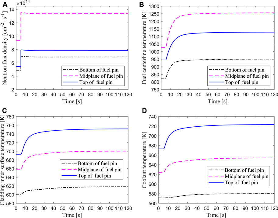
FIGURE 9. Transient responses of the average channel when the intensity of proton beam increased by 50%.
For the hottest channel, three cases of beam step increase by 100, 150, and 200% are carried out. Figure 10 shows that the core power rises rapidly after a sudden increase of the beam intensity, and the increase in power is almost proportional to the increase in beam current. With the rapid increase of the power, the temperatures of the fuel, cladding, and coolant also rise rapidly. Due to the negative reactivity introduced by the Doppler feedback effect and the coolant temperature feedback effect, the power rises to the highest value and then gradually drops to a new stable value. In these three overpower accidents, the maximum fuel temperature is 2456 K, which is lower than the melting point. However, the maximum temperature of the cladding inner surface reaches 1030K when the beam current increases by 200%, as shown in Figure 10C, which is close to the temperature limit of the cladding breakage. After the beam intensity suddenly increases by more than twice the steady-state value, the high temperature of the cladding may endanger the fuel elements in the core hot channel.
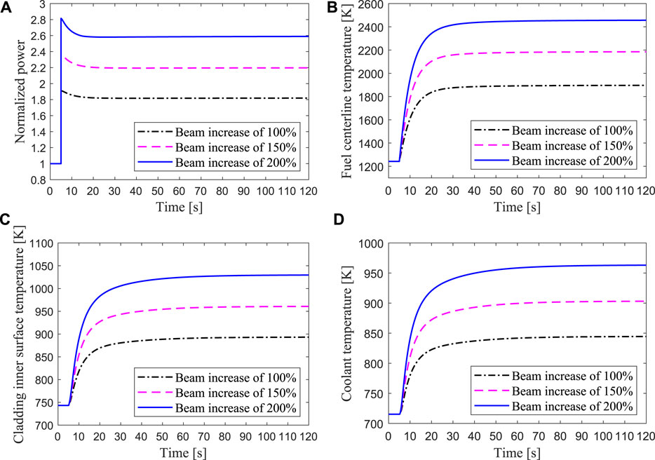
FIGURE 10. Transient responses of the hottest channel when the intensity of proton beam increased by 100, 150, 200% respectively.
3.3 Reactivity Insertion Accident
The reactivity insertion accidents may be caused by the unanticipated control rod ejection. From the previous analysis results, as long as the maximum temperatures of the materials in the hot channel do not exceed the limit, it can be determined that the fuel elements in other channels of the core are also safe. Therefore, the transient process of the power and the maximum temperature of the fuel element in the hottest channel is mainly simulated and analyzed. Three positive reactivity insertions of 300, 600, and 900pcm are investigated in the present study. Two cases are taken into account, i.e., the unprotected case without beam trip and the protected case with reactor shutdown by cutting off the proton beam.
3.3.1 Unprotected Reactivity Insertion
In the case of positive reactivity insertions of 300, 600, and 900pcm in the ADS core during operation, the inherent safety characteristics of the ADS are analyzed by assuming that the emergency protection system has completely failed. The Transient responses of the hottest channel for unprotected reactivity insertions are shown in Figure 11. When different positive reactivity is introduced into the ADS core, the core power rises instantaneously, and then decreases slightly due to the negative feedback effect of the reactivity, and finally reaches a new equilibrium value. Meanwhile, the temperatures of the fuel center, cladding inner surface and coolant outlet also ascend sharply with the power increase and then gradually stabilize to a new equilibrium point. For the 900pcm insertion accident, the maximum temperatures of the fuel center and the cladding inner surface are far below the safety margin. This is principally because the ADS is a subcritical reactor driven by an external neutron source, in which the keff is far from the critical point and the neutron multiplication capacity is weak after the core is inserted 900pcm reactivity. Therefore, the power only rises to 1.32 times the steady-state value, and the peak temperature of fuel and cladding are far below the safety limit under the unprotected reactivity insertion accident. The results show that the ADS has good inherent safety in the event of reactivity insertion accidents, and its margin of criticality safety is large.
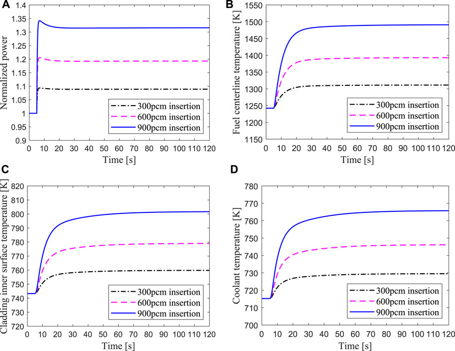
FIGURE 11. Transient responses of the hottest channel for unprotected reactivity insertions of 300, 600, and 900 pcm respectively.
3.3.2 Protected Reactivity Insertion
The results for the protected reactivity insertion at 5s are shown in Figure 12, where the beam shutdown signal occurs at 12s. It can be seen that the power and the temperatures of fuel, cladding, and coolant sharply decrease to the shutdown level after the proton accelerator is closed. It implies that ADS has the inherent safety characteristics to ensure reactor shutdown by cutting off the proton beam.
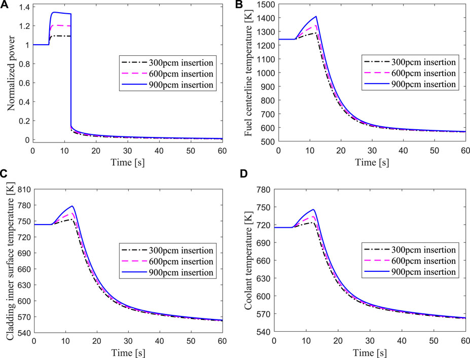
FIGURE 12. Transient responses of the hottest channel for protected reactivity insertions of 300, 600, 900 pcm respectively.
3.4 Loss of Flow Accident
The loss of flow accident is simulated with ARTAP, in which the coolant mass flow step changes from 100 to 10%. Both unprotected and protected cases are considered. The primary coolant pump of the reactor is always equipped with a flywheel with a large inertia to maintain the inertial flow rate of the core after a loss of flow accident and to reduce the consequences of the accident. The influence of the pump stop-time on the reactor flow rate was studied for loss of flow accident in the EBR-II fast reactor (Messick et al., 1987). As shown in Figure 13, three cases of the pump coastdown after the loss of flow accident are simulated respectively, and the flow finally dropped to 10% of the initial value.
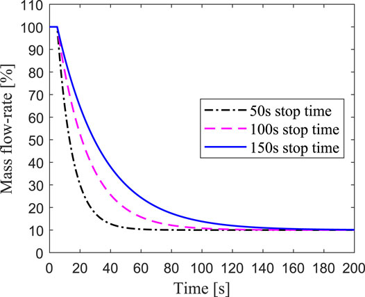
FIGURE 13. Effect of pump coastdown time on mass flow-rate.
3.4.1 Unprotected Loss of Flow
Figure 14 shows that the transient responses of the hottest channel for unprotected loss of flow due to 50, 100, and 150s pump coastdown respectively. The mass flow rate of the hottest channel dropped rapidly after the primary coolant pump stopped, which caused the heat produced by fission reaction in the fuel could not be taken out, and the cladding temperature rose rapidly. The maximum temperature of the cladding inner surface reached 1726K, which means it exceeded the damage limit. The results reveal that protective measures are not taken after the loss of flow accident, the fuel element would rupture, thereby endangering the safety of the ADS core. For one thing, the power drop is small due to the deep subcriticality of the core and low sensitivity to negative reactivity feedback, which is from 100% full power to 88% level. For another, the loss of flow rate prevents the heat transferring from the pellet to the coolant in time, so the temperature of the cladding rises to a very high value. As shown in Figure 14C, for the cases of the pump coastdown time for 50, 100, and 150s, the corresponding time for the cladding temperature reaching the maximum value are 26, 41, and 58s, respectively. Therefore, the protection system should be quickly activated to achieve an emergency shutdown after the loss of flow accident occurs, and the primary pump with a longer coastdown time should be used to ensure the safety of the ADS.
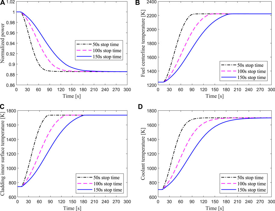
FIGURE 14. Transient responses of the hottest channel for unprotected loss of flow due to 50, 100, 150 s pump coastdown respectively.
3.4.2 Protected Loss of Flow
The results of the protected loss of flow due to 50, 100, and 150s pump coastdown are presented in Figure 15, where the beam shutdown signal occurs at 12s. It can be seen that the power and fuel temperature dropped rapidly and then reached the shutdown level after the proton beam was quickly cut off, in which the core is subcritical without an external neutron source. During this process, the maximum temperature of the fuel center and the cladding surface is lower than the security limit. These simulation results indicate that the ADS core could quickly restore to safety by shutting off the beam under loss of flow accident, and the longer the coastdown time of the primary pump is, the lower the peak temperature of the cladding is.
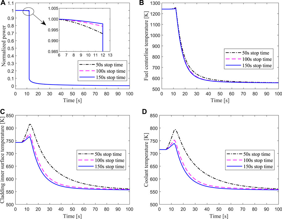
FIGURE 15. Transient responses of the hottest channel for protected loss of flow due to 50, 100, 150 s pump coastdown respectively.
3.5 Loss of Heat Sink Accident
Corresponding to the primary circuit system, the secondary circuit system is a heat sink of the core during the normal operation of ADS. When the cooling system of the secondary circuit fails, such as one or more secondary circuit pumps trip or the air cooler fan stops, insufficient cooling capacity of the core results in a heat sink accident. The ADS system studied in this paper has three secondary loops, in which each loop contains a secondary circuit pump and an air cooler. During the process of heat sink accident, a single or two or all of the circuit pumps in the secondary loop fails, which causes the mass flow of the entire secondary circuit to drop from 100 to 69, 37, and 8% within 20s, respectively.
3.5.1 Unprotected Loss of Heat Sink
Transient responses of the hottest channel for unprotected loss of heat sink due to one, two, or three secondary pump trips are shown in Figure 16. Because the mass flow rate of the secondary side in the heat exchanger drops rapidly after the loss of heat sink accident, the heat of the primary circuit loop could not be removed in time. It can be seen from Figure 16 that the temperatures of the fuel center and the cladding inner surface rise rapidly, and the power drops slightly due to the negative feedback effect of reactivity. The higher the number of failed pumps in the secondary circuit is, the larger the temperature rise of fuel and cladding is. In the case of all the secondary pumps failure, the peak temperature of the cladding surface reaches 934 K, which is lower than the safety limit.
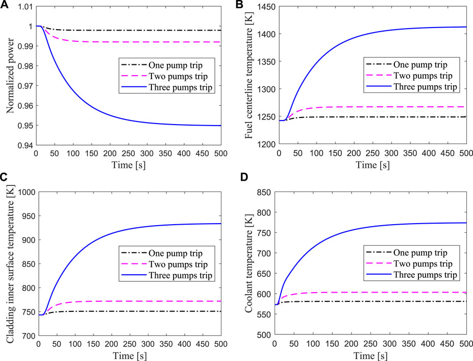
FIGURE 16. Transient responses of the hottest channel for unprotected loss of heat sink due to one, two or three secondary pumps trip respectively.
3.5.2 Protected Loss of Heat Sink
The results of the protected loss of heat sink due to one, two, or three secondary pump trips are shown in Figure 17, where the beam shutdown signal occurs at 12s. The fission energy produced in the core decreases rapidly after the proton beam was quickly cut off, in which the core is subcritical without an external neutron source. Due to the rapid decrease of the power, the temperatures of the fuel center and cladding surface also drop rapidly. The outlet coolant of the core temperature drops quickly with the power decrease after the shutdown protection system is activated, hence the heat transferring from the core to the heat exchanger is correspondingly reduced. These simulation results indicate the safety potential of the LBE-cooled ADS design against loss of heat sink accident.
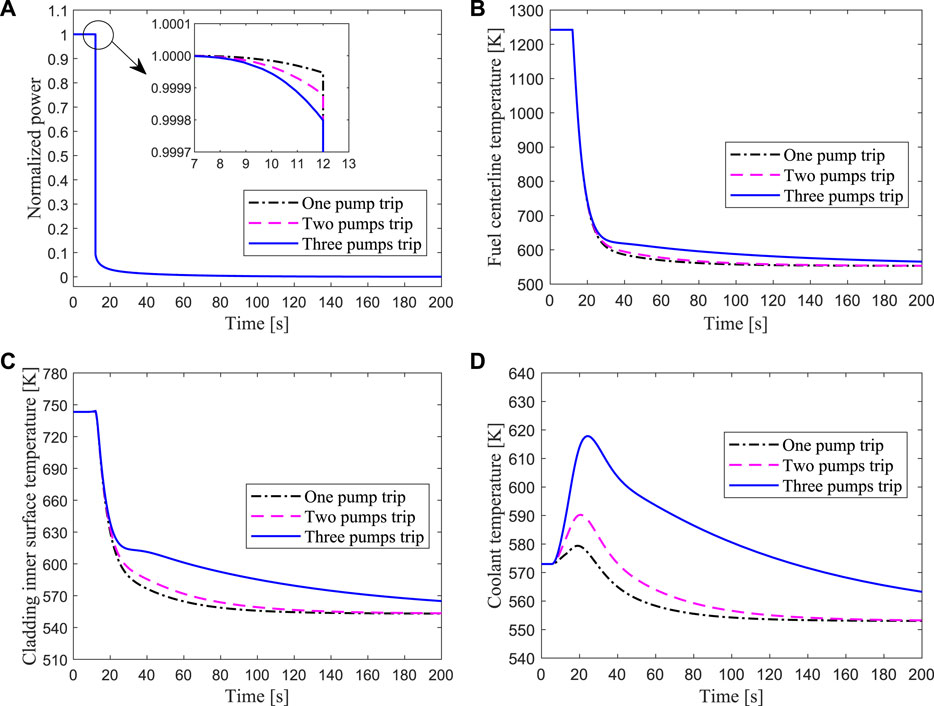
FIGURE 17. Transient responses of the hottest channel for protected loss of heat sink due to one, two or three secondary pumps trip respectively.
4 Conclusion
In the present study, a developed computational code named ARTAP is used to analyze the inherent safety characteristics of the ADS, which comprises of a steady-state analysis module and a transient analysis module. The steady-state analysis module couples a one-dimensional neutron diffusion equation and a thermal-hydraulics single-channel model. According to the initial power distribution obtained by the neutron diffusion calculation, temperature distributions of coolant and fuel could be calculated by the thermal-hydraulics model, which are selected as the feedback parameters to update the macroscopic cross-sections of the neutron diffusion equation, and then a new power distribution is obtained. This coupling iterative process continues until some criterion for convergence is met. The transient analysis module consists of space-time neutron kinetic equations and thermal-hydraulics dynamic equations, which was verified by comparing its results with the those of the OECD/NEA benchmark. In order to investigate the safety characteristics, five typical accidents in an 80 MW LBE-cooled ADS are carried out which include proton beam interruption, transient overpower, reactivity insertion, loss of flow, and loss of heat sink. The transient simulations are performed in the average fuel pin and the hottest fuel pin of the ADS assembly by using the ARTAP code.
The simulation for a beam interruption accident shows that the highest fuel temperature is in the middle of the average channel, while the highest cladding and coolant temperatures are in the top of the average channel. When the beam is interrupted for 20s, the maximum temperature drops of the fuel center, the cladding inner surface and the outlet coolant are 644.46K, 162.27K, and 136.42K respectively. The frequent interruptions may cause thermal fatigue damage of the cladding material in the hottest channel, which will affect the life of the ADS core. For transient overpower accident with 50% increase of beam intensity, the maximum temperature of the fuel center and the cladding surface are 1255 and 751K respectively, both of which are far below the safety limit. After the beam intensity suddenly increases by more than twice the steady-state value, the maximum temperature of the cladding inner surface reaches 1030K, which may damage the fuel element of the hot channel in the core. Concerning the reactivity insertion accident, it was found that the power only rises to 1.32 times the steady-state value, and the peak temperature of fuel and cladding are far below the safety limit after the core is inserted 900 pcm reactivity. The results show that the ADS has good inherent safety in the event of reactivity insertion accidents, and its margin of criticality safety is large. In the simulation of loss of flow accident, the power drop is small due to the deep subcriticality of the core and low sensitivity to negative reactivity feedback, which ranges from 100% full power to 88% level. The maximum temperature of the cladding inner surface reaches 1726K, that means the fuel element would rupture. After the protection system is activated, the power and the temperatures of fuel, cladding and coolant sharply decrease to the shutdown level after the proton accelerator is closed. It implies that ADS have the inherent safety characeristics to ensure reactor shutdown by cutting off the proton beam. The simulation results of Loss of heat sink accident show that the higher the number of failed pumps in the secondary circuit is, the larger the temperature rise of fuel and cladding is. In the case of all the secondary pumps failure, the peak temperature of the cladding surface reaches 934 K, which is lower than the safety limit. The present simulation results reveal that the ADS system has a remarkable advantage against severe accidents. It also implies that ADS has the inherent safety characteristics to ensure reactor shutdown by cutting off the proton beam.
Data Availability Statement
The original contributions presented in the study are included in the article/Supplementary Material, further inquiries can be directed to the corresponding author.
Author Contributions
RL: Conceptualization, Methodology, Software, Validation, Data curation, Writing - original draft. SR: Methodology, Writing - review and editing. DZ: Visualization, Data curation. FZ: Supervision, Writing - review and editing.
Funding
This research is supported by the Scientific Research Foundation of the Education Department of Hunan Province, China (Grant No. 18B265); High-tech Program of the Science and Technology Bureau of Hengyang City, China (Grant No. S2018G9031015321); Fundamental Research Fund for Young Teachers of the University of South China (Grant No. 190XQD064).
Conflict of Interest
The authors declare that the research was conducted in the absence of any commercial or financial relationships that could be construed as a potential conflict of interest.
Publisher’s Note
All claims expressed in this article are solely those of the authors and do not necessarily represent those of their affiliated organizations, or those of the publisher, the editors and the reviewers. Any product that may be evaluated in this article, or claim that may be made by its manufacturer, is not guaranteed or endorsed by the publisher.
References
Bobkov, V., Fokin, L., Petrov, E., Popov, V., Rumiantsev, V., and Savvatimsky, A. (2008). Thermophysical Properties of Materials for Nuclear Engineering: A Tutorial and Collection of Data. Vienna: IAEA.
Cammi, A., Luzzi, L., Porta, A. A., and Ricotti, M. E. (2006). Modelling and Control Strategy of the Italian Lbe-Xads. Prog. Nucl. Energ. 48, 578–589. doi:10.1016/j.pnucene.2006.03.006
Chen, X., Suzuki, T., Rineiski, A., Wiegner, E., Maschek, W., and Flad, M. (2003). “Unprotected Transients in a Small Scale Accelerator Driven System,” in Proc. International Topical Meeting on Nuclear Applications of Accelerator Technology (AccApp’03), 1–5.
Cinotti, L., Giraud, B., and Abderrahim, H. A. (2004). The Experimental Accelerator Driven System (Xads) Designs in the Euratom 5th Framework Programme. J. Nucl. Mater. 335, 148–155. doi:10.1016/j.jnucmat.2004.07.006
D’Angelo, A., Arien, B., Sobolev, V., Van den Eynde, G., and Gabrielli, F. (2003). Benchmark on Beam Interruptions in an Accelerator-Driven System, Final Report on Phase I Calculations. Nucl. Sci. NEA/NSC/DOC 17.
D’Angelo, A., Arien, B., Sobolev, V., Van den Eynde, G., and Gabrielli, F. (2004). Benchmark on Beam Interruptions in an Accelerator-Driven System, Final Report on Phase Ii Calculations. Nucl. Sci. NEA/NSC/DOC 79.
Duderstadt, J. J., and Hamilton, L. J. (1976). Nuclear Reactor Analysis. New York: John Wiley & Sons.
Eriksson, M., Cahalan, J. E., and Yang, W. S. (2005). On the Performance of point Kinetics for the Analysis of Accelerator-Driven Systems. Nucl. Sci. Eng. 149, 298–311. doi:10.13182/nse03-103
Hill, R., and Khalil, H. (2001). Physics Studies for Sodium Cooled ATW Blanket. Lemont, IL, US: Tech. rep., Argonne National Lab.
Huang, Y.-L., Liu, L.-B., Jiang, T.-C., Wang, R.-X., Zhang, S.-X., Guo, H., et al. (2021). 650 Mhz Elliptical Superconducting Rf Cavities for Ciads Project. Nucl. Instr. Methods Phys. Res. Section A: Acc. Spectrometers, Detectors Associated Equipment 988, 164906. doi:10.1016/j.nima.2020.164906
Kumar, V. V., and Katovsky, K. (2020). “A Comprehensive Review of Developments of Accelerator Driven Subcritical Systems and Future Requirements,” in 2020 21st International Scientific Conference on Electric Power Engineering (EPE) (Prague, Czech Republic: IEEE), 1–6. doi:10.1109/epe51172.2020.9269179
Lu, T., Shan, J., Gou, J., Zhang, B., Zhang, B., Ge, L., et al. (2016). Preliminary Safety Analysis on Loss of Flow Accidents and External Source Transients for Lbe Cooled Adsr Core. Prog. Nucl. Energ. 88, 134–146. doi:10.1016/j.pnucene.2016.01.001
Luo, R., Song, H., Zhang, L., and Zhao, F. (2015). Study of Minor Actinides Effect on Kinetic Parameters and Reactivity Coefficients in an Accelerator Driven System. Prog. Nucl. Energ. 83, 419–426. doi:10.1016/j.pnucene.2015.05.001
Luo, R., Wang, P., Wei, X., Revankar, S. T., and Zhao, F. (2018). “Development of Neutronics and thermal-hydraulics Coupled Code for Accelerator Driven Subcritical Systems,” in 2018 26th International Conference on Nuclear Engineering (American Society of Mechanical Engineers Digital Collection). doi:10.1115/icone26-81276
Mansani, L. (2002). Specification for Core and Fuel Element Design for the Lbe-Cooled Xads. PDS-XADS Deliverable D2.
Maschek, W., Chen, X., Delage, F., Fernandez-Carretero, A., Haas, D., Matzerath Boccaccini, C., et al. (2008). Accelerator Driven Systems for Transmutation: Fuel Development, Design and Safety. Prog. Nucl. Energ. 50, 333–340. doi:10.1016/j.pnucene.2007.11.066
Messick, N. C., Betten, P. R., Booty, W. F., Christensen, L. J., Fryer, R. M., Mohr, D., et al. (1987). Modification of Ebr-Ii Plant to Conduct Loss-Of-Flow-Without-Scram Tests. Nucl. Eng. Des. 101, 13–23. doi:10.1016/0029-5493(87)90146-4
Park, W. S., Shin, U., Han, S.-J., Song, T. Y., Choi, B. H., and Park, C. K. (2000). Hyper (Hybrid Power Extraction Reactor): A System for Clean Nuclear Energy. Nucl. Eng. Des. 199, 155–165. doi:10.1016/s0029-5493(99)00066-7
Pfrang, W., and Struwe, D. (2007). Assessment of Correlations for Heat Transfer to the Coolant for Heavy Liquid Metal Cooled Core Designs, Vol. 7352. Karlsruhe, BW: FZKA.
Rineiski, A., and Maschek, W. (2005). Kinetics Models for Safety Studies of Accelerator Driven Systems. Ann. Nucl. Energ. 32, 1348–1365. doi:10.1016/j.anucene.2005.03.007
Schikorr, W. M. (2001). Assessments of the Kinetic and Dynamic Transient Behavior of Sub-critical Systems (Ads) in Comparison to Critical Reactor Systems. Nucl. Eng. Des. 210, 95–123. doi:10.1016/s0029-5493(01)00431-9
Shampine, L. F., Reichelt, M. W., and Kierzenka, J. A. (1999). Solving index-1 Daes in Matlab and Simulink. SIAM Rev. 41, 538–552. doi:10.1137/s003614459933425x
Sobolev, V. (2011). Database of Thermophysical Properties of Liquid Metal Coolants for Gen-Iv. Mol, Belgium: Scientific Rep. the Belgian Nuclear Research Centre.
Song, H., Luo, R., Wan, J., Li, S., and Zhao, F. (2016). Development of a Novel 1d Coupled neutronics/thermal-hydraulics Code and its Verification on Pwr Rod Ejection Accident Benchmark. Prog. Nucl. Energ. 92, 197–210. doi:10.1016/j.pnucene.2016.07.008
Sugawara, T., Takei, H., Iwamoto, H., Oizumi, A., Nishihara, K., and Tsujimoto, K. (2018). Research and Development Activities for Accelerator-Driven System in Jaea. Prog. Nucl. Energ. 106, 27–33. doi:10.1016/j.pnucene.2018.02.007
Suzuki, T., Chen, X.-N., Rineiski, A., and Maschek, W. (2005). Transient Analyses for Accelerator Driven System Pds-Xads Using the Extended Simmer-Iii Code. Nucl. Eng. Des. 235, 2594–2611. doi:10.1016/j.nucengdes.2005.06.012
Van Tuyle, G., Hill, D., Beller, D., Bishop, W., Cotton, T., Finck, P., et al. (2001). A Roadmap for Developing ATW Technology: System Scenarios & Integration. Prog. Nucl. Energ. 38, 3–23. doi:10.1016/s0149-1970(00)00094-9
Wang, G., Gu, Z., Wang, Z., and Jin, M. (2015a). Verification of Neutronics and thermal-hydraulics Coupled Simulation Program Ntc by the Pds-Xads Transient Simulation. Prog. Nucl. Energ. 85, 659–667. doi:10.1016/j.pnucene.2015.08.013
Wang, Z., Wang, G., Gu, Z., Jin, M., and Wu, Y. (2015b). Benchmark of Neutronics and thermal-hydraulics Coupled Simulation Program Ntc on Beam Interruptions in Xads. Ann. Nucl. Energ. 77, 172–175. doi:10.1016/j.anucene.2014.11.017
Wu, Y. (2016). Design and R&D Progress of China Lead-Based Reactor for ADS Research Facility. Engineering 2, 124–131. doi:10.1016/j.eng.2016.01.023
Wulff, W., Cheng, H., and Mallen, A. (1985). Analytical Modeling Techniques for Efficient Heat Transfer Simulation in Nuclear Power Plant Transients. Tech. rep., Brookhaven Natl. Lab.
Yang, W. S., and Khalil, H. S. (2001). Blanket Design Studies of a lead bismuth Eutectic-Cooled Accelerator Transmutation of Waste System. Nucl. Technol. 135, 162–182. doi:10.13182/nt135-162
Keywords: accelerator driven system, neutronics, thermal-hydraulics, safety analysis, accident
Citation: Luo R, Revankar ST, Zhang D and Zhao F (2022) Inherent Safety Characteristics of Lead Bismuth Eutectic-Cooled Accelerator Driven Subcritical Systems. Front. Energy Res. 10:699599. doi: 10.3389/fenrg.2022.699599
Received: 23 April 2021; Accepted: 07 February 2022;
Published: 09 March 2022.
Edited by:
Ivan Vrbanic, APOSS d.o.o., CroatiaReviewed by:
Muhammad Saeed, East China University of Technology, ChinaZhu Rongsheng, Jiangsu University, China
Copyright © 2022 Luo, Revankar, Zhang and Zhao. This is an open-access article distributed under the terms of the Creative Commons Attribution License (CC BY). The use, distribution or reproduction in other forums is permitted, provided the original author(s) and the copyright owner(s) are credited and that the original publication in this journal is cited, in accordance with accepted academic practice. No use, distribution or reproduction is permitted which does not comply with these terms.
*Correspondence: Run Luo, luorun@usc.edu.cn, runluozh@163.com