 Shuhuai Shi
 Junli Du
 Binbing Xia2
- 1State Grid Henan Electric Power Research Institute, Zhengzhou, China
- 2School of Electrical Engineering, Xi’an Jiaotong University, Xi’an, China
The Dual Active Bridge (DAB) DC-DC converter has the ability of bidirectional power transmission and the modulation scheme that is easy to implement, which can ensure the efficient transmission of energy in the system. Therefore, it is often used in various scenarios of small DC grid, such as energy storage, photovoltaic system, electric vehicle charging and so on. The main methods to improve the efficiency of dual active bridge include reducing the effective value of current and widening the soft switching area. Based on the above idea, an optimized extended phase-shift (EPS) modulation strategy is proposed in this paper. The modulation strategy achieves the goal of reducing the effective value of the current through the constraint optimization of the corresponding variables, and then improves the efficiency of the converter. In this paper, the working principles of several typical modulation strategies are introduced in detail, and then the power characteristics and soft-switching characteristics of the new method and other commonly used modulation schemes are analyzed and compared. Finally, the effectiveness of the optimization method for extended phase-shift modulation strategy is verified by the dual active bridge experimental prototype.
1 Introduction
Simple equipment structure and strong ability to connect different distributed generations (Marquardt, 2010; Lin et al., 2016; Liu et al., 2020). In DC distributed energy generation system, DC/DC converters connect different DC voltage buses and renewable resources (Xiong et al., 2015; Zhao et al., 2015; Liu et al., 2022a). Therefore, its performance determines the economy, reliability and stability of the whole DC distribution system (Cornea et al., 2017; Pannala et al., 2020; Xiong et al., 2022).
However, the duty cycle of the trigger pulse under phase-shift modulation is fixed, which increases the difficulty of adjusting the soft switching region. Therefore, reference (Xu et al., 2004; Inoue and Akagi, 2007; Park and Choi, 2014; Chen et al., 2017; Li and Shi, 2019) proposed an asymmetric duty cycle modulation (ADM) scheme with duty cycle as the control variable. Compared with phase-shift modulation, ADM control significantly reduces the current stress and expands the soft-switching range, and its advantages are more obvious when the input voltage does not match the output voltage (Xie et al., 2014; Khan et al., 2015; Hou and Li, 2021; Quan et al., 2022). In addition, ADM control can also be applied to other DC converters, such as double-active half-bridge and three-phase double-active bridge (Kim et al., 2009; Ngo et al., 2012; Chakraborty and Chattopadhyay, 2018; Huang et al., 2019). However, the ADM control contains only two degrees of freedom, which limits the flexibility of the control (Xiong et al., 2021; Zhou et al., 2021; Liu et al., 2022b).
In order to further reduce the current stress characteristics and expand the soft switching region, and then improve the efficiency of DAB, anoptimized EPS modulation scheme is proposed to further reduce the current stress and widen soft-switching range. Firstly, the multi-duty modulation is introduced in detail, including the working principle, typical working waveform and steady-state characteristics. Then, based on MATLAB simulation, the optimization of the current RMS is realized. After that, the comprehensive performance of multi-duty modulation and other traditional modulation methods of DAB is compared, including current RMS, peak current and soft switching characteristics. Finally, a DAB experimental prototype is built, and the effectiveness of the proposed method is verified by experiments.
2 Dual active bridge DC/DC converter
2.1 Operation principle of dual active bridge DC-DC converter
The typical structure of DAB converter in small DC power grid is shown in Figure 1. A typical configuration of the basic structure of topology of the DAB converter is shown in Figure 2, mainly comprising two symmetrical full bridges, an inductor L and a high frequency transformer. The ratio of the transformer is n. The two symmetrical full-bridges are composed of IGBT switches and its corresponding anti-parallel diodes, so they have the advantage of bidirectional energy transmission ability. V1 and V2 are the input and output voltages of the converter, respectively. VH1 and VH2 are the AC equivalent voltages on the primary and secondary sides of the high-frequency transformer, respectively. The voltage matching ratio k is defined herein as follows.
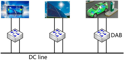
FIGURE 1. The DAB converter applied to small DC power grid topology.
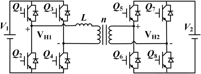
FIGURE 2. The typical topology of DAB converter.
According to the voltage matching ratio k and the transmission power P of the converter, the operation modes of the DAB converter can be divided into the following four types.
1) k > 1, p > 0: Forward Boost Transfer Mode. 2) k < 1, p > 0: Forward Buck Transfer Mode. 3) k > 1, p < 0: Reverse boost transfer model. 4) k < 1, p < 0: Reverse Buck Transfer Mode.
2.2 Fundamentals of extended phase-shift modulation
The modulation optimization strategy of DAB converter mainly focuses on the modulation scheme and the optimization objective function. The modulation scheme determines the operation mode and steady state of the DAB converter. The selection of the optimization target is closely related to the optimization effect and the implementation method. Therefore, the basic principle and typical operation waveforms of EPS modulation are introduced in this section.
Under the control of EPS, the primary H-bridge is modulated with an inner phase-shift ratioD1 which is between Q1 and Q4, and the secondary H-bridge is modulated by SPS. D2 is the external phase shift ratio between IGBT Q1 and Q5.
Figure 3 shows the four typical operating waveforms under EPS modulation schemes and device conduction interval without direct power transfer. Figure 3 also shows the AC equivalent waveforms VH1 and VH2, the inductor current iL waveform, and the trigger pulse waveform of the switch tube in two typical working modes under the control of EPS. When the voltage conversion ratio k > 1 (k < 1), DAB works in buck (boost) mode. The equations of transmission power are expressed as follows.
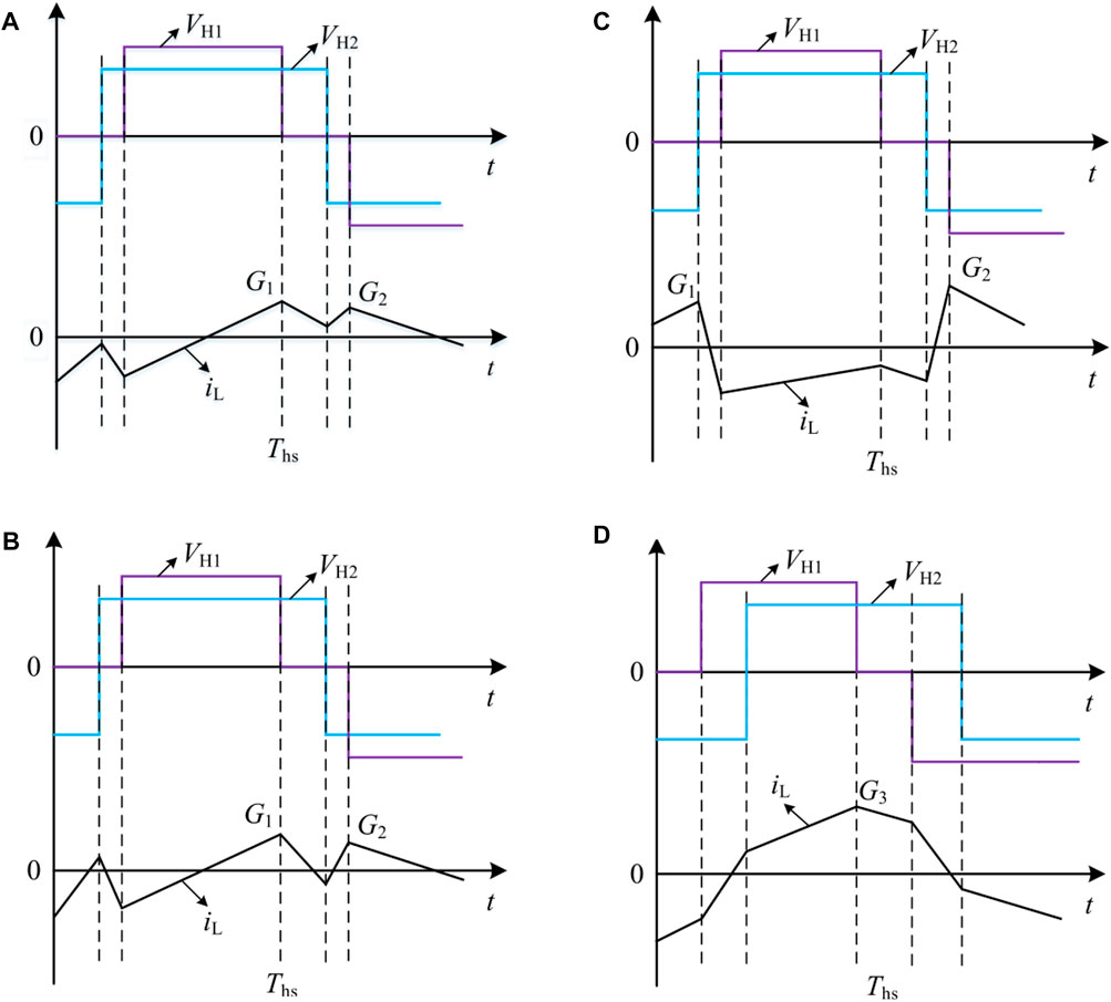
FIGURE 3. The operation waveform for EPS modulation of DAB converter: (A) EPS mode A; (B) EPS mode B; (C) EPS mode C; (D) EPS mode D.
The reference transmission power can be defined as follows.
3 Optimized EPS modulation strategy
Determining the optimization objectives and constraints of EPS control, this paper takes EPSoperating mode 2 as an example to analyze soft-switching characteristics and corresponding optimizations.
The ZVS condition is important to reduce switching losses. The ZVS of each IGBT depends on the current direction at each switching instant. In EPS Mode 2, all devices can achieve ZVS. Figure 4 shows a detailed analysis of ZVS in EPS operating mode 2.
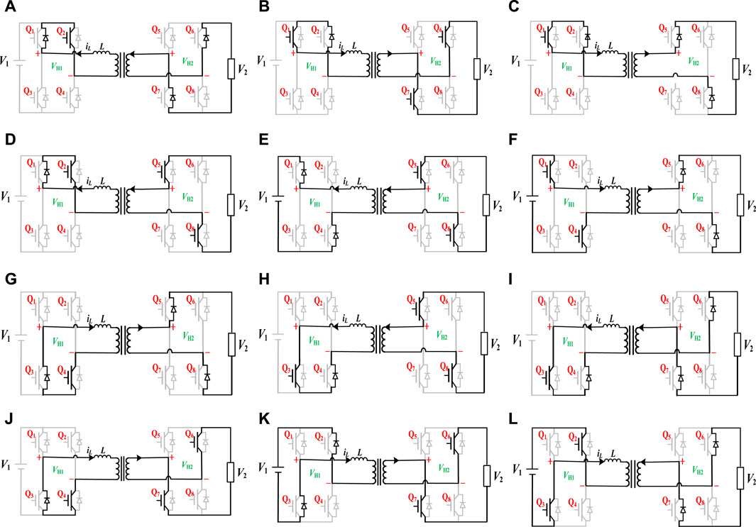
FIGURE 4. The circuit configuration of detailed ZVS analysis under optimized EPS mode: (A) period 1 from t0 to t1; (B) period 2 from t1 to t2; (C) period 3 from t2 to t3; (D) period 4 from t3 to t4; (E) period 5 from t4 to t5; (F) period 6 from t5 to t6; (G) period 7 from t6 to t7; (H) period 8 from t7 to t8; (I) period 9 from t8 to t9; (J) period 9 from t9 to t10; (J) period 10 from t10 to t11; (K) period 11 from t11 to t12; (L) period 12 from t12 to t13.
In this paper, the RMS current is taken as the optimization target to further reduce the device loss and copper loss. EPS control contains two control degrees of freedom (D1–D2) and its optimization is also restricted by power level P and voltage matching ratio k, which increases the difficulty of current RMS optimization, and also makes the traditional optimization methods such as derivation method and Lagrange multiplier method no longer applicable. Therefore, the optimization of the effective value of the current under EPS control needs to be realized by means of a reasonable optimization algorithm.
For EPS control, the optimization objective is to minimize the current effective value, where the current effective value is expressed as follows, where the voltage matching ratio k is a given value, and the duty cycles D1–D2 are the quantities to be solved.
The switching loss of the switch tube includes turn-on loss and turn-off loss, and the reduction of the turn-on loss can be realized by optimizing the modulation method to make each device realize ZVS. The premise of ZVS is that the turn-on voltage of the device drops to 0 before the device is turned on. Therefore, if the diode is turned on before the switch tube is turned on, the ZVS of the IGBT can be realized. In EPS operating mode 1, all devices achieve ZVS.
Therefore, the current RMS optimization under EPS control has two non-equality constraints: boundary condition and ZVS.
(1) ZVS: Current direction at each switching instant.
(2) Operation boundary in each operation mode. The current RMS optimization under EPS control also has the equality constraint that the transmission power should be equal to the given value of the transmission power, as shown in formula.
Figure 5 is a control block diagram of the DAB converter under the control of the EPS. And calculating the voltage matching ratio according to V1 and V2, performing constraint optimization calculation on the calculated duty ratio, and obtaining the duty ratios D1 and D2 according to k. Then according to the EPS modulation method proposed in this paper, the trigger signals of all IGBTs are obtained to make DAB operate normally.
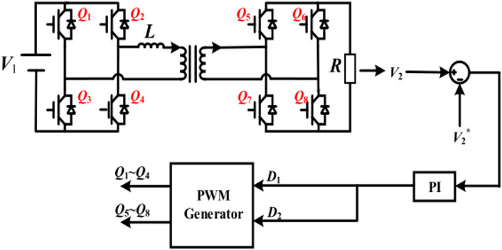
FIGURE 5. The control block diagram of DAB converter under optimized EPS control.
4 Comparison of operating characteristics of different modulation strategies
In order to verify the effectiveness of the above theoretical analysis and the optimized EPS control, this paper compares the traditional SPS control, EPS control 1 andEPS control 2 and the optimizedEPS control under the same transmission power.
4.1 Current RMS comparison
Figures 6A–D, respectively show the distribution of the current effective value corresponding to different modulation strategies in the full power range under different voltage matching ratios. It can be seen that the current effective value under SPS control is the largest, and the current effective value is obviously larger under the matching ratio of light load and low voltage. Optimized EPS control proposed in this paper, EPS control 1 and EPS control 2 can effectively reduce the RMS current of the converter by increasing the modulation control variable. Among these modulation strategies, the optimized EPS modulation has the lowest effective control current in the whole power range.
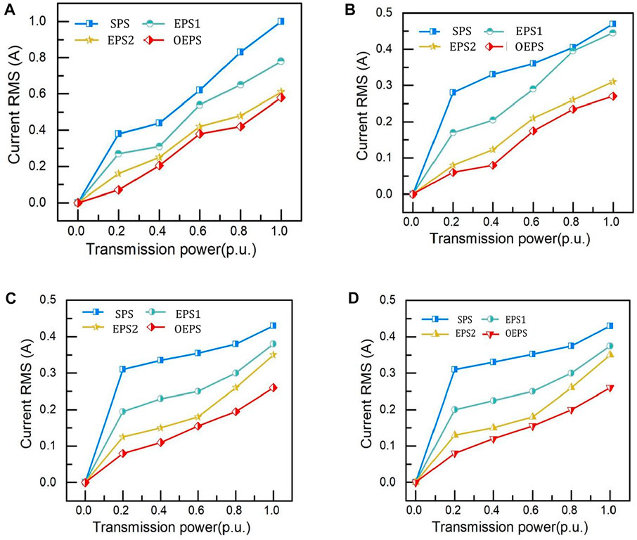
FIGURE 6. The Comparison of current RMS values under different modulation strategies and k: (A) k = .25; (B) k = .5; (C) k = 1; (D) k = 2.
4.2 Soft switching range comparison
The increase in switching losses may have a negative impact on the efficiency improvement and heat dissipation of the DAB converter. Widening the soft switching region of the converter is beneficial to eliminating the turn-on loss of the DAB switch tube, especially widening the ZVS region of all IGBTs. Figure 7 shows the soft switching regions of the above modulation strategy under different transmission power P and voltage matching ratios k. It can be seen from the figure that, compared with other modulation strategies, the ZVS region of all IGBT devices under optimized EPS control is the widest. Therefore, the optimized EPS control can extend the soft-switching range and effectively reduce the switching losses of the switches.
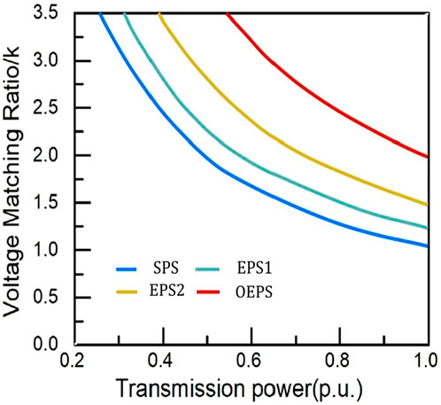
FIGURE 7. The soft-switching performance under different modulation schemes.
4.3 Efficiency comparison
The efficiency comparison of different modulation strategies is shown in Figure 8, from which it can be seen that the efficiency of the optimized EPS control method proposed in this paper is the highest in the full power range.
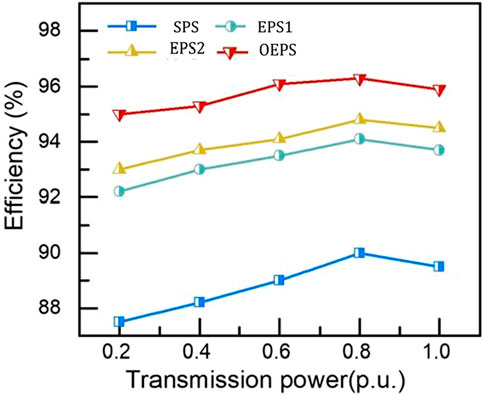
FIGURE 8. The efficiency comparison between different modulation schemes.
5 Experimental verification
The DAB converter test platform is shown in Figure 9. It consists of two symmetrical H-bridges, a high-frequency transformer, an inductor and a DSP controller. Table 1 shows the specific parameter values of the experimental platform, in which the transformation ratio of the high-frequency transformer is n = 1.
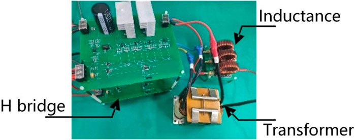
FIGURE 9. The DAB-based experimental prototype.

TABLE 1. Parameters of the DAB-based prototype.
Figures 10A–D are experimental waveforms of optimized EPS control, SPS, EPS control 1, and EPS control 2, respectively, at a transmission power p = .45 (p.u.) with a voltage matching ratio k = 1. Table 2 lists the minimum values of the peak-to-peak current and the effective current of all device under different modulations. Based on the experimental results in Figure 10 and Table 2, it can be seen that, compared with the existing modulation methods, optimized EPS control proposed in this paper has better performance in terms of the expansion of the soft switching region and the reduction of the current effective value.
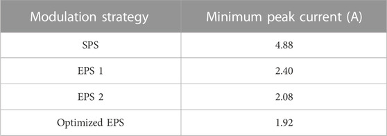
TABLE 2. The lowest current stress with all semiconductors ZVS.
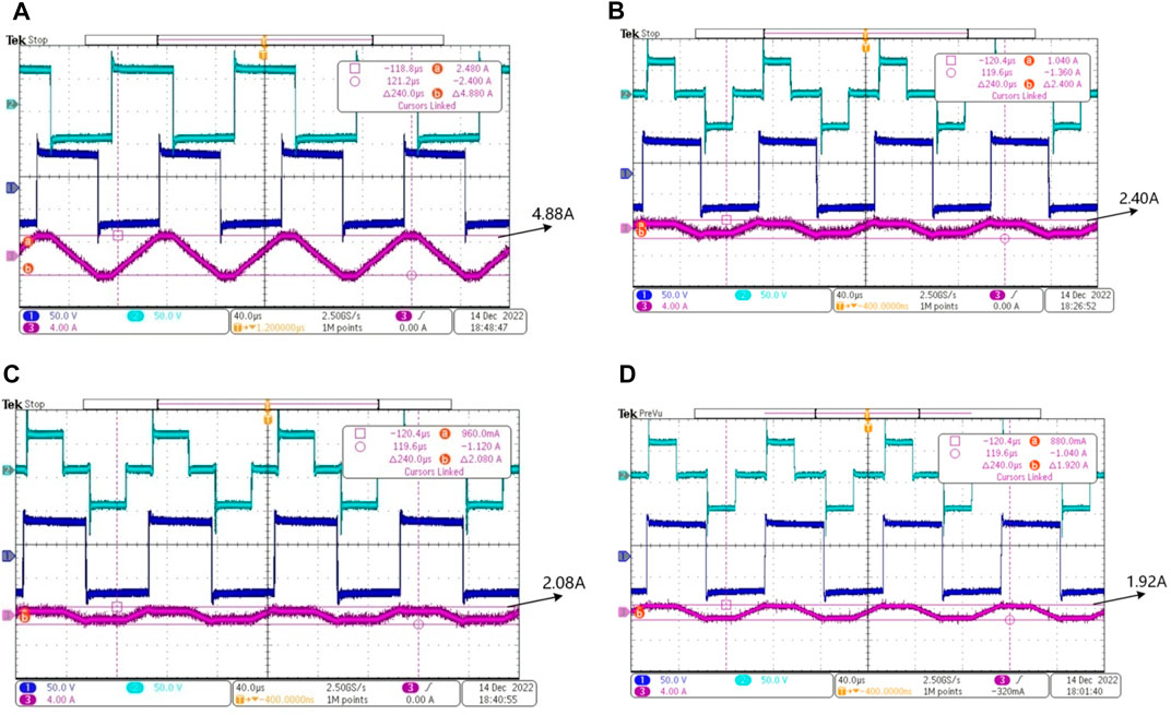
FIGURE 10. The waveform under different modulation schemes: (A) Optimized EPS; (B) EPS 1; (C) EPS 2; (D) SPS.
6 Conclusion
An optimized EPS modulation strategy is proposed in this paper, which can reduce the RMS current and broaden the soft-switching region, and then improve the efficiency of DAB converter. The optimized EPS modulation strategy uses the algorithm of constrained optimization for achieving the optimization goal of reducing the effective value of current. Compared with the traditional optimization methods, the proposed method has the advantages of low operation complexity and high optimization speed. The above results are verified by MATLAB simulation. Finally, based on the built DAB experimental platform, the RMS current, soft-switching range and efficiency of the proposed optimized EPS modulation strategy are compared with those of other commonly used modulation strategies. The comparison of multiple dimensions shows that the proposed optimized EPS modulation strategy can reduce the RMS current and improve the efficiency, and broaden the soft-switching range of the device. This method provides the possibility for DAB converter to be applied in the scenario of high efficiency and high power density.
Data availability statement
The original contributions presented in the study are included in the article/supplementary material, further inquiries can be directed to the corresponding author.
Author contributions
SS and JD contributed to the conception of the study and performed the data analyses and wrote the manuscript. BX and HG performed the simulation validation. DX and FW contributed significantly to analysis and manuscript preparation.
Conflict of interest
Authors SS, JD, DX, and HG were employed by the company State Grid Henan Electric Power Research Institute.
The remaining authors declare that the research was conducted in the absence of any commercial or financial relationships that could be construed as a potential conflict of interest.
Publisher’s note
All claims expressed in this article are solely those of the authors and do not necessarily represent those of their affiliated organizations, or those of the publisher, the editors and the reviewers. Any product that may be evaluated in this article, or claim that may be made by its manufacturer, is not guaranteed or endorsed by the publisher.
References
Chakraborty, S., and Chattopadhyay, S. (2018). Fully ZVS, minimum RMS current operation of the dual-active half-bridge converter using closed-loop three-degree-of-freedom control. IEEE Trans. Power Electron. 33 (12), 10188–10199. doi:10.1109/TPEL.2018.2811640
Chen, Y., Zhang, N., Wang, K., Yang, J., and Kang, Y. (2017). A series resonant filament power supply with variable structure and oscillation-free switching strategy for high-voltage accelerator application. IEEE Trans. Power Electron. 32 (11), 8229–8236. doi:10.1109/TPEL.2017.2690800
Cornea, O., Andreescu, G-D., Muntean, N., and Hulea, D. (2017). Bidirectional power flow control in a DC microgrid through a switched-capacitor cell hybrid DC–DC converter. IEEE Trans. Industrial Electron. 64 (4), 3012–3022. doi:10.1109/TIE.2016.2631527
Hou, N., and Li, Y. (2021). Communication-free power management strategy for the multiple DAB-based energy storage system in islanded DC microgrid. IEEE Trans. Power Electron. 36 (4), 4828–4838. doi:10.1109/TPEL.2020.3019761
Huang, J., Li, Z., Shi, L., Wang, Y., and Zhu, J. (2019). Optimized modulation and dynamic control of a three-phase dual active bridge converter with variable duty cycles. IEEE Trans. Power Electron. 34 (3), 2856–2873. doi:10.1109/TPEL.2018.2842021
Inoue, S., and Akagi, H. (2007). A bidirectional DC–DC converter for an energy storage system with galvanic isolation. IEEE Trans. Power Electron. 22 (6), 2299–2306. doi:10.1109/TPEL.2007.909248
Khan, M. A., Ahmed, A., Husain, I., Sozer, Y., and Badawy, M. (2015). Performance analysis of bidirectional DC–DC converters for electric vehicles. IEEE Trans. Industry Appl. 51 (4), 3442–3452. doi:10.1109/TIA.2015.2388862
Kim, J., Jeong, I., and Nam, K. (2009). “Asymmetric duty control of the dual-active-bridge DC/DC converter for single-phase distributed generators,” in 2009 IEEE Energy Conversion Congress and Exposition, San Jose, CA, USA, 20-24 Sept. 2009, 75–82.
Li, R., and Shi, F. (2019). Control and optimization of residential photovoltaic power generation system with high efficiency isolated bidirectional DC–DC converter. IEEE Access 7, 116107–116122. doi:10.1109/ACCESS.2019.2935344
Lin, W., Wen, J., Yao, L., and Yang, B. (2016). “Step-up unidirectional DC-DC autotransformer for HVDC applications,” in Power Electronics and Motion Control Conference, Hefei, 22-26 May 2016, 703–707.
Liu, X., Grassi, F., Spadacini, G., and Pignari, S. A. (2020). Physically based modeling of hand-assembled wire bundles for accurate EMC Prediction. IEEE Trans. Electromagn. Compat. 62 (3), 914–922. doi:10.1109/TEMC.2019.2922455
Liu, X., Wu, B., and Xiu, L. (2022a). A fast positive-sequence component extraction method with multiple disturbances in unbalanced conditions. IEEE Trans. Power Electron. 37 (8), 8820–8824. doi:10.1109/tpel.2022.3161734
Liu, X., Xiong, L., Wu, B., Qian, Y., and Liu, Y. (2022b). Phase locked-loop with decaying DC transient removal for three-phase grids. Int. J. Electr. Power & Energy Syst. 143, 108508. doi:10.1016/j.ijepes.2022.108508
Marquardt, R. (2010). “Modular Multilevel Converter: An universal concept for HVDC-Networks and extended DC-Bus-applications,” in Power Electronics Conference, Sapporo Japan, 21-24 June, 502–507. doi:10.1109/IPEC.2010.5544594
Ngo, T., Won, J., and Nam, K. (2012). “A single-phase bidirectional dual active half-bridge converter,” in 2012 Twenty-Seventh Annual IEEE Applied Power Electronics Conference and Exposition Orlando, FL, USA, 05-09 February 2012, 1127–1133.
Pannala, S., Patari, N., Srivastava, A. K., and Padhy, N. P. (2020). Effective control and management scheme for isolated and grid connected DC microgrid. IEEE Trans. Industry Appl. 56 (6), 6767–6780. doi:10.1109/TIA.2020.3015819
Park, J., and Choi, S. (2014). Design and control of a bidirectional resonant DC–DC converter for automotive engine/battery hybrid power generators. IEEE Trans. Power Electron. 29 (7), 3748–3757. doi:10.1109/TPEL.2013.2281826
Quan, S., Su, S., and Zhao, N. (2022). Design method of dual active bridge based on the optimum efficiency. J. Electr. Eng. 17 (02), 56–64. doi:10.11985/2022.02.007
Xie, Y., Huang, J., Liu, X., Zhuo, F., Liu, B., Zhang, H., et al. (2014). “PV system modeling and a global-planning design for its controller parameters,” in Proceedings of the IEEE Applied Power Electronics Conference and Exposition - APEC 2014, Fort Worth, TX, USA, 16-20 March 2014, 3132–3135.
Xiong, L., Zhuo, F., Liu, X., Wang, F., Chen, Y., Zhu, M., et al. (2015). “Research on fast open-loop phase locking scheme for three-phase unbalanced grid,” in Proceedings of the 2015 IEEE Applied Power Electronics Conference and Exposition (APEC), 15-19 March 2015, 1672–1676.
Xiong, L., Liu, L., Liu, X., and Liu, Y. (2021). Frequency trajectory planning based strategy for improving frequency stability of droop-controlled inverter based standalone power systems. IEEE J. Emerg. Sel. Top. Circuits Syst. 11 (1), 176–187. doi:10.1109/JETCAS.2021.3052006
Xiong, L., Liu, X., Liu, Y., and Zhuo, F. (2022). Modeling and stability issues of voltage-source converter-dominated power systems: A review. CSEE J. Power Energy Syst. 8 (6), 1530–1549. doi:10.17775/CSEEJPES.2020.03590
Xu, D., Zhao, C., and Fan, H. (2004). A PWM plus phase-shift control bidirectional DC–DC converter. IEEE Trans. Power Electron. 19 (3), 666–675. doi:10.1109/TPEL.2004.826485
Zhao, B., Song, Q., Liu, W., and Zhao, Y. (2015). Universal high-frequency-link characterization and practical fundamental-optimal strategy for dual-active-bridge DC-DC converter under PWM plus phase-shift control. IEEE Trans. Power Electron. 30 (12), 6488–6494. doi:10.1109/TPEL.2015.2430934
Keywords: dual-active-bridge converter, efficiency, soft switching, modulation strategy, constrained optimization
Citation: Shi S, Du J, Xia B, Xia D, Guan H and Wang F (2023) Research on optimum extended phase-shift control with minimum peak-to-peak current of DAB converter applied to small DC power grid. Front. Energy Res. 10:1115146. doi: 10.3389/fenrg.2022.1115146
Received: 03 December 2022; Accepted: 23 December 2022;
Published: 10 January 2023.
Edited by:
Di Cao, University of Electronic Science and Technology of China, ChinaReviewed by:
Tianhua Zhu, Aalborg University, DenmarkBo Chen, Tianjin University, China
Changkun Du, Beijing Institute of Technology, China
Copyright © 2023 Shi, Du, Xia, Xia, Guan and Wang. This is an open-access article distributed under the terms of the Creative Commons Attribution License (CC BY). The use, distribution or reproduction in other forums is permitted, provided the original author(s) and the copyright owner(s) are credited and that the original publication in this journal is cited, in accordance with accepted academic practice. No use, distribution or reproduction is permitted which does not comply with these terms.
*Correspondence: Shuhuai Shi, c2hpc2h1aHVhaUAxMjYuY29t