 Lin Zhu1
 Qi Liu
 Zixin Zhou
95% of researchers rate our articles as excellent or good
Learn more about the work of our research integrity team to safeguard the quality of each article we publish.
Find out more
ORIGINAL RESEARCH article
Front. Energy Res. , 13 January 2023
Sec. Smart Grids
Volume 10 - 2022 | https://doi.org/10.3389/fenrg.2022.1109277
This article is part of the Research Topic Operation and Control in Smart Electric Power Systems: Methods and Applications View all 5 articles
Compared to conventional DC transmission, Voltage source converter based high voltage direct current transmission (VSC-HVDC) has the advantages of independently controllable transmission power, no commutation failure, no reactive power compensation and low harmonic levels. However, VSC-HVDC transmission cannot provide effective frequency support and regulation for the system after grid connection. For this reason, an adaptive neural fuzzy virtual inertia control method is proposed to impose a control strategy on the converter at the receiving end of a VSC-HVDC transmission. The method uses the frequency change rate and the amount of change of frequency as constraints to dynamically adjust the virtual inertia and damping coefficients. It provides larger inertial support when the frequency fluctuation is large and smaller inertial support when the frequency fluctuation is small, thus adapting to different operating conditions. Finally, a hardware-in-the-loop simulation platform is built. The superiority and application prospect of the proposed strategy in frequency stability of the system are verified by comparing the proposed strategy with the traditional virtual control strategy.
With the goal of carbon neutrality and carbon peaking, the proportion of renewable energy generation is gradually increasing (Fei et al., 2018; Choopan et al., 2019). Distributed power sources, mainly photovoltaic and wind power generations, are integrated into the grid through flexible DC transmission, enabling the interconnection of two different frequency AC systems and facilitating their respective dispatch and operation. Compared to traditional transmission methods, VSC-HVDC transmission has the advantages of fast response time, good controllability and flexible operation methods (Rassol et al., 2018; Eggers et al., 2019; Liu et al., 2016). But with large-scale power electronic equipment connected to the system, it has little inertia of its own, leading to poor stability of the whole system when the renewable energy output as well as the load changes (Liu and Chen, 2013). It is therefore necessary to investigate the corresponding strategies to enable VSC-HVDC transmission systems to support system frequency stability.
Several scholars have conducted research on the inertial support of VSC-HVDC transmission for system frequency stability. The paper (Fathi et al., 2018) proposes a virtual synchronous generator control (VSG) for the frequency regulation of the system with the participation of the converter at the receiving end of the VSC-HVDC transmission. The paper (Torres L. et al., 2014) improves the virtual synchronous generator control by entering the integral control of frequency deviations to achieve deviation-free regulation of the AC system. The paper (Bidadfar et al., 2016) analyses the electrical oscillations that occur during the grid connection of a direct-drive permanent magnet fans (PMSG) and the influence of the PI parameters of the network-side converter on the oscillations. The paper (Li et al., 2019) presents the concept of virtual power for virtual synchronous generators and improves the amplitude–frequency characteristics of virtual power. To address the problem of frequency stability in grid-connected flexible DC transmission (VSC-HVDC), the paper (Donde et al., 2016; Langwasser et al., 2021; Man et al., 2020) analyses the oscillation characteristics of the frequency and makes improvements based on the characteristics The paper (Alipoor et al., 2015) investigates the value of virtual inertia for virtual synchronous generator control and proposes a virtual inertia value with hybrid stationary energy as the energy source. The paper (Wang X. et al., 2018; Wang et al., 2021; Zhu et al., 2021) investigate the frequency response model of VSG and proposes a constant value and integrated velocity recovery method. The paper (Guo et al., 2021) proposes an improved VSG pre-synchronous control strategy for ship power systems with a large number of harmonics. The paper (Rouzbehi et al., 2014; Zhou et al., 2018; Zhang et al., 2021) study the power control and load flow control of flexible HVDC. In (Jiang et al., 2019; Ren et al., 2020), the converter of flexible DC transmission is studied, and the method to reduce the failure rate and improve the reliability of AC/DC power grid is proposed based on state enumeration. The paper (Duan et al., 2021) proposes an analogous virtual synchronous generator control for multi-port converters with simultaneous implementation of droop, virtual inertia and damping characteristics. The paper (Rathore et al., 2016; Sakaeda et al., 2017) optimizes the inertia constant and virtual virtual coefficient of vsg according to frequency deviation and voltage deviation The paper (Liu and Gong, 2020) analyses the effect of droop-control on the stability in VSC-HVDC transmission systems and verifies the isolation of DC systems from low frequency oscillations through simulation. The above control strategies all play a stable role in the regulation of the system frequency, but the regulation mode is relatively single, it is difficult to cope with a variety of different operating conditions, while the speed and sensitivity of the regulation of the frequency are poor.
Combining these issues, the paper (Rehman et al., 2021) adaptively improves the system inertia by adjusting different virtual inertia values in real time to achieve fast smoothing out frequency fluctuations. The paper (Fan et al., 2017) investigates the power angle characteristics in the case of output current saturation when VSG is used and proposes an adaptive inertia control strategy. The paper (Li and yang et al., 2022) realizes the cooperative distribution of virtual inertia for each unit of hybrid energy storage through fuzzy control. In (Gomis-Bellmunt et al., 2020) flexible virtual inertia control of VSC-HVDC transmission systems containing optical storage is carried out in stages according to frequency variations to ensure frequency stability. In (Feiyang et al., 2021), an integrated control method for adaptive inertia damping was designed to achieve interleaved control of virtual rotational inertia and virtual damping. However, all of these methods have the disadvantage of being more complex to model and slower to converge with the other constraints added.
An adaptive neural fuzzy virtual inertia control for VSC-HVDC transmission systems is proposed in this paper. Firstly, this strategy solves the inertia problem that exists in flexible DC transmission systems. Secondly, this strategy links the frequency and virtual inertia values together and the virtual inertia values can be allocated flexibly. So that larger virtual inertia values can be allocated when the frequency fluctuation is large and smaller virtual inertia values can be allocated when the frequency fluctuation is small, which can meet the operating condition of different working conditions. At the same time, this strategy uses a fuzzy neural network system to adjust the optimal virtual inertia values and damping coefficients through the rapid iteration of the neural network, which has better speed and accuracy and enables the system to achieve better stability. Finally, the paper verifies the proposed adaptive neural fuzzy virtual inertia control strategy through the hardware-in-the-loop simulation platform.
A typical VSC-HVDC system is shown in Figure 1. It consists of two synchronous generator ports (SG1, SG2), one VSC-HVDC grid-connected port and three active power loads.
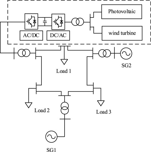
FIGURE 1. Topology of a VSC-HVDC system.
Where the synchronous generator SG1 is used for secondary frequency regulation of the system and the synchronous generator SG2 is used for constant power control. Renewable energy generation in the VSC-HVDC grid-connected port is connected to the system through rectifier and inverter stations. The rectifier side uses constant voltage control to provide a reference voltage for the system and to maintain voltage stability. The control method proposed in this paper is mainly used on the inverter side to provide inertial support for the system to maintain the system frequency within the rated range.
The topology structure of the VSC-HVDC transmission system is shown in Figure 2, in which the VSC1 rectifier is the power sending end, the VSC2 is the power receiving end. US and Uc are the AC voltage and DC voltage respectively, and L and R are the line equivalent inductance and resistance. The main component of the converter is the commutation valve, which controls the system flow by controlling the switching on and off of the IGBT devices on the VSC bridge arm. VSC-HVDC system generally uses constant voltage control and through the voltage outer loop output active current reference value. The inner loop tracking active current command to obtain the converter D-axis voltage component and Q-axis voltage component according to the reactive current command, so as to maintain the stability of the system voltage and provide the reference voltage for the system. As both sides are structurally identical, one side can be taken for analysis, starting with the inverted side. The model of the converter in the stationary coordinate system is shown in Eq. 1 and the topology of VSC2 is shown in Figure 3.
Where: ugx, igx, ucx are the AC grid-side voltage, AC grid-side current, converter-side voltage. Rg, Lg are the resistance and inductance values of the filter reactor.
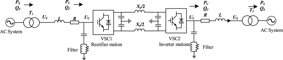
FIGURE 2. Topology of a VSC-HVDC system.
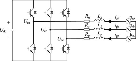
FIGURE 3. Topology of VSC2.
The Pike transformation is performed to derive the voltage equation for VSC2 in a dq-synchronous rotating coordinate system.
Where: ucd, ucq are the output voltages of VSC2 in the dq coordinate system respectively. Ugd, ugq, igd, igq are the d-axis and q-axis components of the AC grid voltage and current respectively. ωs is the AC system frequency.
Where:
For power, a voltage-directed vector control method orienting the voltage vector to the d-axis of the synchronous rotation coordinate system is used so that ugd = ug and ugq = 0, achieving a decoupling of active and reactive power.
Where PG denotes the output active power flowing from the network to the VSC2 and QG denotes the output reactive power flowing in the network to VSC2.
The d-axis and q-axis components of the converter voltage are not decoupled, thus introducing feedforward compensation terms Δucd and Δucq to decouple the d-axis and q-axis components, and the decoupling control diagram is shown in Figure 4.
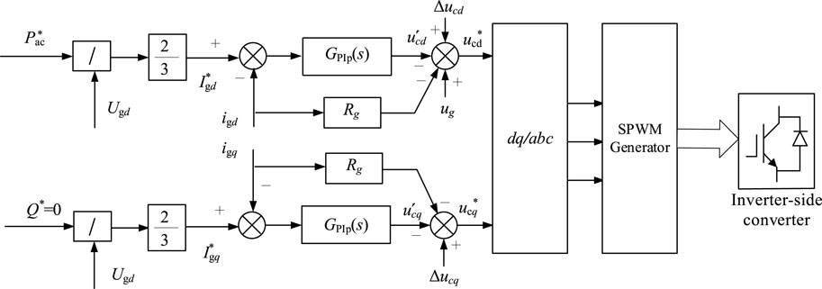
FIGURE 4. Control topology of VSC2.
Virtual synchronous generator control provides inertial support to the system in the event of a disturbance by introducing the rotor equations of motion into the investigated control strategy of the converter, giving the converter the characteristics of inertia and damping contained in a conventional generator.
The rotor active power-frequency equation is shown in Eq. 6.
where ω denotes the virtual angular frequency of the inverter power supply and ω0 denotes the grid-side angular frequency respectively. H denotes the value of the virtual inertia. P denotes the output power of the inverter power supply. Pref is the reference value of active power. θ denotes the phase angle of the inverter power supply. Kd denotes the damping coefficient of the system.
From the rotor equation of motion, it is clear that the active power changes with frequency. When it is disturbed, the frequency of the system changes, at which point the active output of the inverter power supply changes and can provide power support like a conventional generator, quickly replenishing the power deficit present in the system and maintaining the system frequency quality.
In steady state operation, the amplitude of the frequency change is finite and the rotor equation of motion can be simplified as shown in Eq. 7.
From the simplified equation, the active power is proportional to the value of the virtual inertia. The control of the system power and frequency can be achieved through the adjustment of the virtual inertia. Due to the proportional relationship, when the system is subjected to a large disturbance resulting in a large change in frequency, it is required that a large virtual inertia value should be provided at this time. Conversely, smaller virtual inertia values should be provided for small perturbations.
For conventional VSC-HVDC transmission, an adaptive neural fuzzy virtual inertia control is proposed based on the conventional VSG control. This control strategy is applied at the receiving end of the VSC-HVDC system to provide inertial support for the system, as shown in the control block diagram in Figure 5.
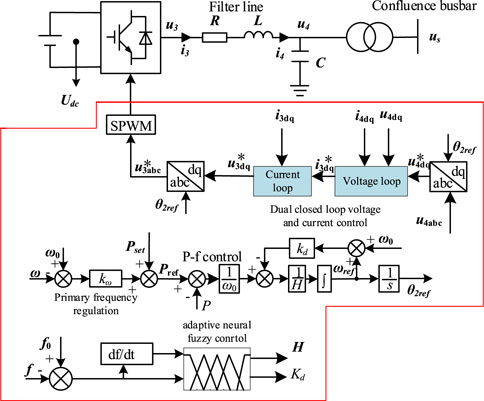
FIGURE 5. Adaptive inertial control block diagram.
Where ω and ω0 denote the virtual angular frequency of the inverter power supply and the grid-side angular frequency respectively. H denotes the value of the virtual inertia. P denotes the output power of the inverter power supply. Pref is the active scheduling command of the system. θ denotes the phase angle of the inverter power supply. Kd denotes the damping coefficient of the system. F indicates the actual frequency of the system and f0 is the system frequency setting.
As can be seen from the control block diagram, unlike the traditional VSG control, this control strategy takes the amount of change of frequency and the rate of change of frequency as the constraint indicators, and flexibly adjusts the virtual inertia value H and the damping coefficient Kd through the adaptive neural fuzzy control system, so that the system can allocate a larger virtual inertia value when the frequency fluctuation is large and a smaller virtual inertia value when the frequency fluctuation is small.
Traditional fuzzy control does not require precise mathematical models and is highly adaptable to non-linearities, but relies on the experience and knowledge of experts or operators, which can make it difficult to achieve satisfactory control results if the experience is lacking. Neural network systems are self-learning. Adaptive neural fuzzy control systems are data-based modeling methods in which fuzzy membership functions and fuzzy rules are obtained by learning from large amounts of known data, rather than being arbitrarily given based on experience and intuition, and are particularly important for the control of complex systems. The elimination of noise or interference in signal processing and control can be achieved, while the inertia and damping coefficients can be dynamically adjusted to suit different operating conditions.
Traditional fuzzy control mainly includes fuzzification, fuzzy inference, and defuzzification three processes, the main process is shown in Figure 6.
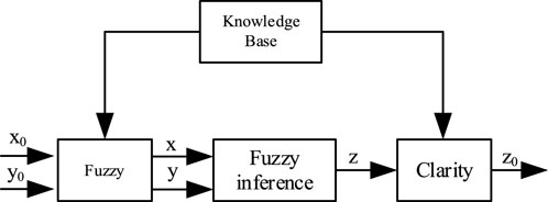
FIGURE 6. The process of fuzzy control.
A fuzzy neural network model based on the Takagi-Sugeno model is selected for inference, and all the three basic processes of fuzzification, fuzzy inference and defuzzification of fuzzy control are implemented by neural networks. The amount of change of frequency ke and the rate of change of frequency ked are selected as the inputs to the fuzzy system and the outputs are the virtual inertia H and the damping coefficient kd.
where f0 is the rated value of the frequency and f is the frequency of the grid.
Let the input vector be
where Aij is the jth linguistic variable value of xi and the corresponding membership function is
The posterior of the fuzzy rule proposed by the Takagi-Sugeno model is a linear combination of the input variables.
where j denotes the number of output variables and y denotes the output value which is also the virtual inertia H and the damping coefficient Kd. p denotes the connection right of the network. mi is the number of fuzzy partitions of xi.
The inputs are fuzzified using singleton fuzzy set. For a given input x, the degree of adaptation can be found for each rule as:
The membership function is expressed as a bell-shaped function using a Gaussian function as shown in the following equation.
where cij and σij denote the centre and width of the affiliation function, respectively. For a given fixed input, only the linguistic variable values near the input point have a large membership degree, those far from the input point have small membership degree and finally the normalized calculation has to be implemented.
For a system network of m nodes, each representing a rule, the output of each rule is calculated as shown in the following equation.
The inputs are the amount of frequency change and the rate of frequency change respectively, so n takes the value of 2.
The final weighted output of this neural network system is obtained based on the output of each node and the degree of adaptation.
The adaptive neural fuzzy system makes data processing maximally simple due to the use of Takagi-Sugeno model fuzzy rules and the weighted summation method to calculate the total output, eliminating the extensive computational work involved in clarifying conventional fuzzy systems with the center of gravity method.
The main role of the neural fuzzy controller is to apply its self-learning capability of the neural network to seek and adjust the neural fuzzy control system’s parameters and structure. The number of fuzzy divisions of the input components is given in advance. The only parameters to be learned for the learning algorithm are the connection rights Plji and the central values of the membership functions cij and σij. The learning algorithm can be quickly converged to the required input and output i.e. the relationship between the change of frequency and virtual inertia. Due to the presence of neural networks, the parameters are also easier to learn and adjust.
To further verify the proposed virtual inertial control strategy, a hardware-in-the-loop simulation test platform based on RT-LAB simulator was built.
The adaptive neural network control strategy proposed in this paper is deployed in a DSP controller. A model of the 3-end AC system built as shown in Figure 7 and its basic controls are deployed in RT-LAB. The DSP controller is connected to the AD input ports of the RT-LAB through an opto-isolated module to enable the real-time exchange of control signals. The waveforms during the experiment can be observed with the DL850 wave recorder. In order to observe the experimental results more visually, the data recorded in the recorder can be exported and the different experimental waveforms can be plotted in the same coordinate system using the plotting software.
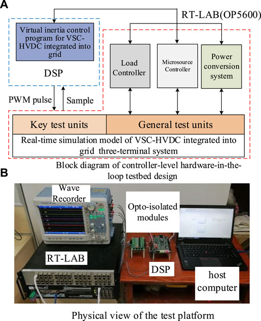
FIGURE 7. Test platform.
In this paper, a 3-machine 9-node system is built in MATLAB to verify the proposed strategy and to compare it with conventional control strategies. The system structure is shown in Figure 1, with a grid level of 35kV and 650V on the low-voltage side of the transformer, SG1 and SG2 are two synchronous generators. The initial moment loads 1, 2, and 3 are each 250kW, the system is already in a steady state at 9s and the system load is adjusted at 14s when adaptive neural fuzzy virtual inertia control is put in place.
Operating condition 1 is a 350 kW load increase at 14s of system operation. The frequency fluctuation response in the three modes of without inertia control, fixed inertia control and adaptive neural fuzzy inertia control is shown respectively in Figure 8.
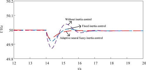
FIGURE 8. Frequency fluctuations during load increasing.
The frequency fluctuation without inertia control is the greatest, with a maximum overshoot of nearly 0.14Hz. The control effect of fixed inertia control is better than the control without inertia, with a maximum value of only 0.08 Hz for frequency fluctuations. The system under adaptive neural fuzzy virtual inertia control has the smallest frequency fluctuations and the best system stability.
Operating condition 2 is a 350 kW load decrease at 14s of system operation. The frequency fluctuation response for the three modes of without inertia control, fixed inertia control and adaptive neural fuzzy virtual inertia control is shown respectively in Figure 9.
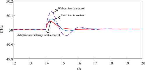
FIGURE 9. Frequency fluctuations during load decreasing.
The degree of frequency fluctuation is greatest without inertia control, with a maximum overshoot of nearly 0.13Hz. Fixed inertia control is second, with a maximum value of only 0.08 Hz for frequency fluctuations. The system with adaptive neural fuzzy virtual inertia control has the least frequency fluctuation and the system can reach stability at a faster rate.
In practical applications, the load tends to fluctuate randomly, so operating condition 3 changes the system load between 14 and 18s. A comparison of the frequency fluctuations for the three different control methods is shown in Figure 10.
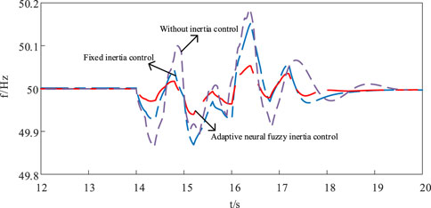
FIGURE 10. Frequency fluctuations during load changing.
The frequency stability effect of the adaptive neural fuzzy virtual inertia control is significantly better than the other two methods under load changing. The frequency fluctuations of the adaptive neural fuzzy virtual inertia control is only 0.05Hz, which can verify the good support effect of this strategy on frequency fluctuations in the practical application process and its superiority for system stability.
Similarly, this paper compares the flexible DC transmission power also under different strategies. Figures 11–13 represent the power variation under three different operating conditions: load increase, load decrease and random load change respectively.
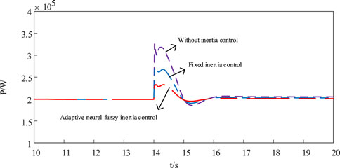
FIGURE 11. Power fluctuations during load increasing.
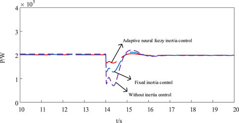
FIGURE 12. Power fluctuations during load decreasing.

FIGURE 13. Power fluctuations during load changing.
The figures show that the flexible DC transmission side quickly provides power support to the system when the system load changes and then returns to a constant output. The comparison of the three different control strategies under different operating conditions shows that the adaptive virtual inertia control strategy has the best effect on the power support of the system, making the system more stable when disturbed, further verifying the effectiveness of this strategy.
VSC-HVDC technology is widely used. In order to improve the stability of VSC-HVDC system against disturbances, this paper proposes an adaptive neural fuzzy virtual inertia control method and verifies the effectiveness of the proposed strategy through experiments and draws the following conclusions.
(1) Virtual inertia control is applied to the receiver converter of VSC-HVDC transmission, and the virtual inertia values and damping coefficients are flexibly adjusted by an adaptive neural fuzzy system to adapt to different operating conditions. Comparing the different control strategies under increasing or decreasing load and random changes in load, the superiority of the present strategy in terms of inertial support and frequency stability is verified.
(2) This method only considers the case where one port is connected to the grid using VSC-HVDC transmission, the actual system consists of multiple ports and the situation is more complex, the inertia distribution between the ports and the synergy of the power output at each end also need to be considered, which is the focus of the next research.
The original contributions presented in the study are included in the article/supplementary material, further inquiries can be directed to the corresponding author.
LZ, QL, SL, ZW, JM, LG, and ZZ were responsible for the main writing of the paper. All authors contributed to the article and approved the submitted version.
This work was supported by the Science and Technology Project of State Grid Corporation of China (5100-202158335A-0-0-00) (Research of Construction and Coordinated Control of VSC-LCC Hybrid Ultra-HVDC System).
Authors LZ, QL, and SL were employed by the company of State Grid Smart Grid Research Institute Co., Ltd. ZW was employed by the company of State Grid Anhui Electric Power Co., Ltd.
The remaining authors declare that the research was conducted in the absence of any commercial or financial relationships that could be construed as a potential conflict of interest.
The authors declare that this study received funding from State Grid Corporation of China. The funder had the following involvement in the study: the decision to submit it for publication.
All claims expressed in this article are solely those of the authors and do not necessarily represent those of their affiliated organizations, or those of the publisher, the editors and the reviewers. Any product that may be evaluated in this article, or claim that may be made by its manufacturer, is not guaranteed or endorsed by the publisher.
Alipoor, J., Miura, Y., and Ise, T. (2015). Power system stabilization using virtual synchronous generator with alternating moment of inertia. IEEE J. Emerg. Sel. Top. Power Electron. 3 (2), 451–458. doi:10.1109/JESTPE.2014.2362530
Bidadfar, A., Nee, H. P., Zhang, L., Harnefors, L., Namayantavana, S., Abedi, M., et al. (2016). Power system stability analysis using feedback control system modeling including HVDC transmission links. IEEE Trans. Power Syst. 31 (1), 116–124. doi:10.1109/TPWRS.2015.2407192
Choopani, M., Hosseinain, S. H., and Vahidi, B. (2019). A novel comprehensive method to enhance stability of multi-VSG grids. Int. J. Electr. Power & Energy Syst. 104, 502–514. doi:10.1016/j.ijepes.2018.07.027
Donde, V., Feng, X., Segerqvist, I., and Callavik, M. (2016). Distributed state estimation of hybrid AC/HVDC grids by network decomposition. IEEE Trans. Smart Grid. 7 (2), 974–981. doi:10.1109/TSG.2015.2457932
Duan, Q., and Zhao, C. (2021). “Improved VSG controlled SST in a low-voltage AC distribution network,” in Proceedings of the 2021 IEEE Sustainable Power and Energy Conference (iSPEC), 428–435. doi:10.1109/iSPEC53008.2021.9736015Nanjing, China
Eggers, M., Yang, H., Just, H., Dieckerhoff, S., and Yin, H. (2019). “Multi-objective parameter optimization of multiple VSG and droop controlled inverters for grid-connected and islanded operation,” in Proceedings of the 2019 20th Workshop on Control and Modeling for Power Electronics (COMPEL), Toronto, ON, Canada 1–7. doi:10.1109/COMPEL.2019.8769648
Fan, W., Yan, X., and Hua, T. (2017). “Adaptive parameter control strategy of VSG for improving system transient stability,” in Proceedings of the 2017 IEEE 3rd International Future Energy Electronics Conference and ECCE Asia (IFEEC 2017 - ECCE Asia), Kaohsiung, Taiwan 2053–2058. doi:10.1109/IFEEC.2017.7992367
Fathi, A., Shafiee, Q., and Bevrani, H. (2018). Robust frequency control of microgrids using an extended virtual synchronous generator. IEEE Trans. Power Syst. 33 (6), 6289–6297. doi:10.1109/TPWRS.2018.2850880
Fei, W., Zhang, L., Feng, X., and Guo, H. (2018). An adaptive control strategy for virtual synchronous generator. IEEE Trans. Ind. Appl. 54 (5), 5124–5133. doi:10.1109/TIA.2018.2859384
Feiyang, D., Zexin, Z., Xingguo, W., Yarong, G., Dingxiang, D., and Qi, C. (2021). “Time-domain characteristic analysis of fault induced traveling wave in flexible DC transmission lines,” in Proceedings of the 2021 International Conference on Power System Technology (POWERCON), Haikou, China 1795–1804. doi:10.1109/POWERCON53785.2021.9697749
Gomis-Bellmunt, O., Sau-Bassols, J., Prieto-Araujo, E., and Cheah-Mane, M. (2020). Flexible converters for meshed HVDC grids: From flexible AC transmission systems (FACTS) to flexible DC grids. IEEE Trans. Power Deliv. 35 (1), 2–15. doi:10.1109/TPWRD.2019.2939588
Guo, W., Tang, X., Xu, Y., and Wang, T. (2021). “Research on marine VSG grid-connected pre-synchronization control strategy,” in Proceedings of the 2021 6th International Conference on Transportation Information and Safety (ICTIS), Wuhan, China 648–654. doi:10.1109/ICTIS54573.2021.9798483
Jiang, L., Bie, Z., Li, G., Huang, G., and Wang, L. (2019). “Reliability evaluation of AC-DC hybrid grid based on state enumeration method,” in Proceedings of the 2019 IEEE 8th International Conference on Advanced Power System Automation and Protection (APAP)), Xi'an, China 391–395. doi:10.1109/APAP47170.2019.9225052
Langwasser, M., De Carne, G., Liserre, M., and Biskoping, M. M. (2021). Primary frequency regulation using HVDC terminals controlling voltage dependent loads. IEEE Trans. Power Deliv. 36 (2), 710–720. doi:10.1109/TPWRD.2020.2990565
Li, C., Yang, Y., Mijatovic, N., and Dragicevic, T. (2022). Frequency stability assessment of grid-forming VSG in framework of MPME with feedforward decoupling control strategy. IEEE Trans. Ind. Electron. 69 (7), 6903–6913. doi:10.1109/TIE.2021.3099236
Li, Z., and Jia, X. (2019). An improved VSG control strategy based on the amplitude-frequency characteristics of virtual power. IEEE Access 7, 101096–101105. doi:10.1109/ACCESS.2019.2930623
Liu, J., Miura, Y., and Ise, T. (2016). Comparison of dynamic characteristics between virtual synchronous generator and droop control in inverter-based distributed generators. IEEE Trans. Power Electron. 31 (5), 3600–3611. doi:10.1109/TPEL.2015.2465852
Liu, X., and Gong, R. (2020). “A control strategy of microgrid-connected system based on VSG,” in Proceedings of the 2020 IEEE International Conference on Power, Intelligent Computing and Systems (ICPICS), Shenyang, China 739–743. doi:10.1109/ICPICS50287.2020.9201955
Liu, Y., and Chen, Z. (2013). A flexible power control method of VSC-HVDC link for the enhancement of effective short-circuit ratio in a hybrid multi-infeed HVDC system. IEEE Trans. Power Syst. 28 (2), 1568–1581. doi:10.1109/TPWRS.2012.2222057
Man, J., Xie, X., Xu, S., Zou, C., and Yin, C. (2020). Frequency-coupling impedance model based analysis of a high-frequency resonance incident in an actual MMC-HVDC system. IEEE Trans. Power Deliv. 35 (6), 2963–2971. doi:10.1109/TPWRD.2020.3022504
Rasool, A., Yan, X., Rasool, H., and Guo, H. (2018). Correlation between multiple VSG sources for enhancing the power allocation in microgrid. Proceedings of the 2018 IEEE Electrical Power and Energy Conference (EPEC). Toronto, ON, Canada 1–6. doi:10.1109/EPEC.2018.8598344
Rathore, B., Chakrabarti, S., and Anand, S. (2016). “Frequency response improvement in microgrid using optimized VSG control,” in Proceedings of the 2016 National Power Systems Conference (NPSC), Bhubaneswar, India 1–6. doi:10.1109/NPSC.2016.7858916
Rehman, H. U., Yan, X., Abdelbaky, M. A., Jan, M. U., Iabal, S., Masood, A., et al. (2020). “Droop control design based on advanced particle swarm optimization for grid-connected multi PV-VSG,” in Proceedings of the 16th IET International Conference on AC and DC Power Transmission (ACDC 2020), Beijing China 2214–2220. doi:10.1049/icp.2020.0332
Ren, J., Meng, Y., Kong, J., Wang, D., Li, J., and Kan, Y. (2020). “Development of operation support platform for chongqing-hubei flexible HVDC transmission Project,” in Proceedings of the 2020 IEEE 4th Conference on Energy Internet and Energy System Integration (EI2), Wuhan, China 3319–3323. doi:10.1109/EI250167.2020.9347066
Rouzbehi, K., Miranian, A., Luna, A., and Rodriguez, P. (2014). “Towards fully controllable multi-terminal DC grids using flexible DC transmission systems,” in Proceedings of the 2014 IEEE Energy Conversion Congress and Exposition (ECCE), Pittsburgh, PA, USA 5312–5316. doi:10.1109/ECCE.2014.6954129
Sakaeda, S., Asano, M., Sugimoto, S., Verma, S. C., Uda, R., and Kuroda, K. (2017). “Studies on stabilizing a massive PV penetrated power system using VSG,” in Proceedings of the 2017 IEEE PES Innovative Smart Grid Technologies Conference Europe (ISGT-Europe), Turin, Italy 1–6. doi:10.1109/ISGTEurope.2017.8260320
Torres, M. A. L., Lopes, L. A. C., Morán, L. A. T., and Espinoza C, J. R. (2014). Self-tuning virtual synchronous machine: A control strategy for energy storage systems to support dynamic frequency control. IEEE Trans. Energy Convers. 29 (4), 833–840. doi:10.1109/TEC.2014.2362577
Wang, J., Li, F., Cui, H., and Zhang, Q. (2021). “Impacts of VSG control on frequency response in power systems with high-penetration renewables,” in Proceedings of the 2021 IEEE 5th Conference on Energy Internet and Energy System Integration (EI2) Taiyuan, China, 171–176. doi:10.1109/EI252483.2021.9712880
Wang, X., Peng, S., Dawei, S., and Hui, L. (2018). “Frequency regulation characteristics optimization and analysis of DFIG- VSG based on rotor inertia control,” in Proceedings of the 2018 China International Conference on Electricity Distribution (CICED), Tianjin, China 2051–2055. doi:10.1109/CICED.2018.8592356
Zhang, F., Cao, J., Han, S., Lu, S., Yang, D., and Wu, T. (2021). “Research of teaching experiment platform for flexible AC/DC transmission system,” in Proceedings of the 2021 IEEE 5th Conference on Energy Internet and Energy System Integration (EI2), Taiyuan, China 4161–4166. doi:10.1109/EI252483.2021.9713592
Zhou, L. (2018). “Analysis on control and protection of MMC-based HVDC flexible transmission system,” in Proceedings of the 2018 13th IEEE Conference on Industrial Electronics and Applications (ICIEA), Wuhan, China 1768–1773. doi:10.1109/ICIEA.2018.8397995
Zhu, F., Peng, Z., Hu, W., Wang, H., Zhang, C., Zhao, Z., et al. (2021). “An Improved VSG control strategy for Microgrid,” in Proceedings of the 2021 IEEE International Conference on Electrical Engineering and Mechatronics Technology (ICEEMT), Qingdao, China 338–342. doi:10.1109/ICEEMT52412.2021.9602085
Keywords: virtual synchronous generator control, adaptive neural fuzzy control, VSC-HVDC, inertia, hardware-in-the-loop simulation
Citation: Zhu L, Liu Q, Liu S, Wang Z, Meng J, Gu L and Zhou Z (2023) An adaptive neural fuzzy virtual inertia control method for VSC-HVDC system. Front. Energy Res. 10:1109277. doi: 10.3389/fenrg.2022.1109277
Received: 27 November 2022; Accepted: 30 December 2022;
Published: 13 January 2023.
Edited by:
Yonghui Sun, Hohai University, ChinaReviewed by:
Zhengyang Xu, Tianjin University, ChinaCopyright © 2023 Zhu, Liu, Liu, Wang, Meng, Gu and Zhou. This is an open-access article distributed under the terms of the Creative Commons Attribution License (CC BY). The use, distribution or reproduction in other forums is permitted, provided the original author(s) and the copyright owner(s) are credited and that the original publication in this journal is cited, in accordance with accepted academic practice. No use, distribution or reproduction is permitted which does not comply with these terms.
*Correspondence: Qi Liu, MTIxNzgyMjkxQHFxLmNvbQ==
Disclaimer: All claims expressed in this article are solely those of the authors and do not necessarily represent those of their affiliated organizations, or those of the publisher, the editors and the reviewers. Any product that may be evaluated in this article or claim that may be made by its manufacturer is not guaranteed or endorsed by the publisher.
Research integrity at Frontiers
Learn more about the work of our research integrity team to safeguard the quality of each article we publish.