 Mohamed Alashqar
 Conghuan Yang
 Ying Xue
 Zhaoxi Liu4
 Weiye Zheng
 Xiao-Ping Zhang
- 1Department of Electrical Engineering, School of Naval Architecture and Ocean Engineering, Guangzhou Maritime University, Guangzhou, China
- 2Department of Electronic, Electrical and Systems Engineering, School of Engineering, University of Birmingham, Birmingham, England, United Kingdom
- 3Qatar General Electricity & Water Corporation (KAHRAMAA), Doha, Qatar
- 4School of Electric Power Engineering, South China University of Technology, Guangzhou, China
The electricity demand keeps increasing with development and time, which leads to the need to install more generating units in the grid. Therefore, the fault current levels will rise above the limits of the electrical equipment, particularly when the electric grid becomes meshed and interconnected with neighboring networks. Consequently, the electrical equipment needs to be replaced or use a method that will decrease the fault current to be within the permissible boundaries. The existing solutions such as neutral impedance, current limiting reactor (CLR), and bus splitting have negative impacts on the electric grid. The superconducting fault current limiter (SFCL) appears to be a promising solution. In this paper, the resistive SFCL is proposed to enhance the stability of the interconnected power system. The two-area system is used as a case study for the interconnected power system. Also, the optimal value and locations of the resistive SFCL are analyzed. The results show that the system will remain stable without tuning the power system stabilizer (PSS).
1 Introduction
One of the unique properties of the power system operation is that the electrical speed of all generating units must be the same (Padiyar, 2004). This is known as the synchronous operation of the power system. However, any disturbance to the power system operation can affect the rotating speeds of rotors, i.e., the network frequency (Kundur, 1994; Anderson and Fouad, 2003; Kundur et al., 2004; Padiyar, 2004; Grigsby, 2012). The transient stability (large-disturbance rotor angle stability) is defined as “the ability of the power system to maintain synchronism when subjected to a severe disturbance, such as a short circuit on transmission facilities, loss of generation, or loss of a large load” where the small-signal stability is defined as “the ability of the power system to maintain synchronism when subjected to small disturbances, such as switching of small loads, generators or transmission line tripping, for which the equations that describe the dynamics of the power system may be linearized for analytical purposes.” (Kundur, 1994), (Kundur et al., 2004; Das, 2007; Machowski et al., 2008). It is essential to note that the transient stability is dependent on the operating condition and the perturbation, which makes the analysis of the transient stability more complicated. Also, the linearization analysis does not apply to transient stability analysis (Padiyar, 2004). Under a transient event, the system response involves large excursions of generator rotor angles, power flows, bus voltages, and other system variables. If the resulting angular separation between the machines in the power system remains within certain bounds, the system maintains synchronism. Loss of synchronism because of transient instability, if it occurs, will usually be evident within 2–3 s of the initial disturbance (Kundur, 1994).
The fault levels in the power system drastically increased due to various reasons. For example, the integration of multiple energy sectors (Zheng et al., 2020), the continuous increase in electricity demands, the massive scale of the power plants either conventional or renewable generation, and the expansion of power grid (Koyama and Yanabu, 2009; Sung et al., 2009; Li et al., 2014). Therefore, the stresses caused by excessive fault currents led to high mechanical, electrical, and thermal instabilities of electric networks (Lee et al., 2008). Consequently, the electrical apparatus might be damaged and cause a partial blackout or even a major blackout if the existing switch gears are not upgraded (Anderson and Fouad, 2003), (Grigsby, 2012), (Miyashita et al., 2005; Kodle et al., 2016; Glover et al., 2017). These changes are the main concerns for the transmission system operators because an increase in the fault levels negatively impacts the power system in terms of security and reliability (Ravindranath and Chander, 1977). Therefore, fault-limiting techniques are required. Many effective methods were used, for instance, bus splitting, current limiting reactors, and others. However, each of these has its own limiting factors. For example, using bus splitting will reduce the reliability of the interconnected system. Also, series reactors have drawbacks such as constant high reactive losses, bulky, and contributing to grid voltage drops. Therefore, a new technique should be utilized to overcome the disadvantages (Blair et al., 2012; Son et al., 2012; Jain et al., 2016). Different methods were used to mitigate the transient instability, such as flexible AC transmission system (FACTS) controller, which includes static VAR Compensator (SVC), thyristor-controlled series capacitor (TCSC), static synchronous series compensator (STATCOM) and unified power flow controller (UPFC) (Kamarposhti et al., 2021), (Wang et al., 2020).
Superconducting fault current limiters are superconducting power equipment whose impedance is small in steady-state condition and large in a fault condition. Therefore, SFCLs do not deteriorate power system stability in steady-state conditions and effectively limit the short-circuit currents in a fault condition (Sjostrom et al., 1999). Different types of SFCL are available in the market; resistive SFCLs, shielded Core FCL, SFCL bridge, and saturated iron core FCL. The Resistive SFCLs have been the primary choice for SFCL field experiments. Its popularity due to its simple concept, compact size and weight, and resistant nature (Blair, 2013). The shielded iron core SCFCL, or often called inductive SCFCL advantageous is that there is no current lead to cryogenic temperatures and that the superconductor is exhibited to large currents but low voltages. Like resistive SCFCLs, a quench takes place in the superconductor and therefore a recovery time of several seconds is needed. However, A major drawback of this type is the large volume and weight which is similar to a transformer of the same power rating (Noe and Steurer, 2007). SCFCL bridge rectifiers are made up of diodes or thyristors arranged in a complete bridge configuration. This SFCL type is undesirable because it no longer controls short-circuit current if, for example, one of the semiconductors fails and causes a short circuit. Furthermore, the total losses are rather substantial.
SFCLs are used to minimize the short circuit current to a definite value and have the ability to decrease the levels of fault current within the electricity grid by factors of 3–10 times (Baldan et al., 2007), (Egorova et al., 2013). Under normal circumstances, SFCL is quenched to a temperature of approximately −200°C, which can be accomplished in a cost-efficient way by using liquid nitrogen (Blair et al., 2012), (Sjostrom et al., 1999), (Lee, 2011), (Vojenčiak et al., 2016). This will minimize the material’s resistivity, which means that it will not have any influence on the network under normal conditions (Matsumoto et al., 2010), (Yonemura et al., 2015). However, if the current goes above the nominal, the materials instantaneously lose their properties of superconductivity and work as a typical resistor. During that situation, the current will be reduced to a predefined value (Lee et al., 2008), (Wang et al., 2014). These properties make superconductors work as a self-triggered current limiter. Moreover, significant features introduced by the superconductors, such as negligible voltage drop and energy losses during steady-state operating conditions, enable higher grid loads without upgrading the equipment in the power system (Kovalsky et al., 2005; Zhang et al., 2015; Kumar et al., 2016).
The normalized non-linear relationship between current flow in a superconductor and its resistance is demonstrated in Figure 1. It can be seen from Figure 1 that when a fault develops, the current rises, causing the superconductor to quench and exponentially increase its resistance. Most SFCL designs consider the above behavior to limit the fault current in the first cycle [Electric Power Research Institute (EPRI), 2009], (Khatibi and Bigdeli, 2014). Under normal grid operation, resistive SFCLs use superconducting material as the main current-carrying conductor. The principle of operation is shown in the single-line diagram in the upper half of Figure 1. As mentioned before, the lower plot is a normalized performance of the voltage across Rsc as a function of the ratio of the current through the SFCL device (ILine)to the critical current (Ic) of the superconducting element. The level of the current at which the quench happens is identified by the operating temperature, the size, and the category of the superconductor. The quick rise in resistance produces a voltage across the superconductor and leads the current to convey to a shunt, a combination of resistor and inductor. The shunt’s role is to limit the voltage increase across the superconductor in the quench situation. In essence, the superconductor works like a switch with a millisecond response that stimulates the transition of the load current to the shunt impedance. Theoretically, the initial fault current is restricted to less than one cycle [Electric Power Research Institute (EPRI), 2009].
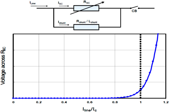
FIGURE 1. Resistive Type SFCL with Shunt Element and a normalized plot of voltage and current in a superconductor at a constant temperature and magnetic field. [Electric Power Research Institute (EPRI), 2009], (Pawar and Chavan, 2017).
Eq. 1 describes the characteristics of the resistive type of SFCL behavior (Chen et al., 2016a), (Moon et al., 2011).
Rn denotes the SFCL’s normal-state resistance; T is the time constant. The SFCL’s time-domain characteristics of t0, t1, and t2 indicate the quench-starting time, the first recovery-starting time, and the secondary recovery-starting time, respectively, as shown in Figure 2. The function coefficients are C1, D1, C2, and D2, as stated in Eq. 1 (Sung et al., 2009), (Chen et al., 2016a), (Elshiekh et al., 2013), (Lim et al., 2009).
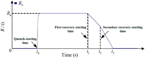
FIGURE 2. Quench/recovery model of the superconducting coil used in the SFCL (Yang et al., 2017), (Chen et al., 2016b).
In this paper, the resistive SCFL is used to verify that the fault current can be minimized significantly. Also, the transient stability of the power system can be enhanced without tuning the PSS. There are difficulties in tuning the PSS because the technique used, simulation study, field implementation, and the number of standard tests to be undertaken for its evaluation differ from utility to utility and vendor to vendor. As a result, the power system planner and the operator must examine and evaluate the efficiency of PSS tuning following the stated criteria for the specific power system. Nevertheless, many power plants have been reported to have tuned their PSS at unit commissioning, during automatic voltage regulator (AVR) modernization, or based on system operator observation/feedback (Wang et al., 2019).
It should be noted that refs (Miyashita et al., 2005), (Pawar and Chavan, 2017), (Mohamed, 2012), and (Wang et al., 2018a) used a single-machine infinite bus (SMIB) to study the improvement of the transient stability by using SCFL. However, each area contributes to the short circuit within the interconnected network in the interconnected power system. Therefore, this paper uses a two-area system with four synchronous machines to analyze the impact of resistive SCFL on angle stability. Different fault locations and fault types are considered in the analysis. Also, the optimal location and value of the resistive SFCL were analyzed.
2 Superconductor fault current limiter
To design a resistive SCFL, five parameters need to be defined (Sung et al., 2009), (Zhang et al., 2015), (Alaraifi et al., 2013), (Wang et al., 2018a):
1 The triggering current (the value at which the SFCL will be stimulated).
2 The quenching resistance (Maximum resistance).
3 The quenching time is the time that the SFCL will be activated.
4 The minimum resistance of 0.01Ω, which is the SFCL’s normal operation resistance.
5 The recovery time of 1 s.
All these parameters have been taken into consideration in designing SFCL. The design of the single phase of the step resistance SFCL model is shown in Figure 3. The principle of operation can be described as follows: firstly, the current measurement is used to measure the current of each phase to compute the absolute and RMS values of the phase line current by RMS block. If the RMS current is less than the triggering current, then the model will consider the SFCL in the normal operating state (superconductivity situation), and the SFCL will take a resistive value of 0.0 L Ω (the minimum resistance). Otherwise, if the RMS value of the line current is higher than the triggering current, then the model will lose the superconductivity state and increase rapidly to the maximum predefined value. Lastly, the fault current drops below the triggering current because the fault was cleared, and the SFCL restores the superconducting condition after recovery. The transport delay block is installed to implement the maximum resistance for 1 s from the moment the fault occurs. The resistive SFCL is connected in series with the transmission line in the event of a short circuit. According to the above-mentioned, the summary of the parameters used in the SFCL modeling can be represented in Table 1.
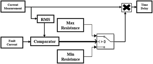
FIGURE 3. Single-phase model of SFCL.
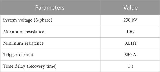
TABLE 1. Parameters used in the SFCL.
3 Power system model
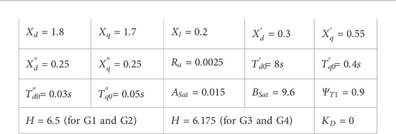
The interconnected two-area system is shown in Figure 4. The system consists of two similar areas connected via a weak tie line (230 kV lines of 220 km length (Kundur, 1994)). Each area has two synchronous generators, and there are 967 MW, and 1767 MW loads at area 1 and area 2, respectively, and the system operates with area 1 exporting 400 MW to area 2; detailed parameters in the Appendix A1. Figure 4 shows the proposed locations of the resistive type SFCL in the interconnected power system, case 1 in Figure 4A, and case 2 in Figure 4B. The power system has been modeled in MATLAB and SIMULINK software to perform different scenarios. In the simulation studies, different types of faults are applied in different locations on line one to demonstrate the performance of SFCLs.
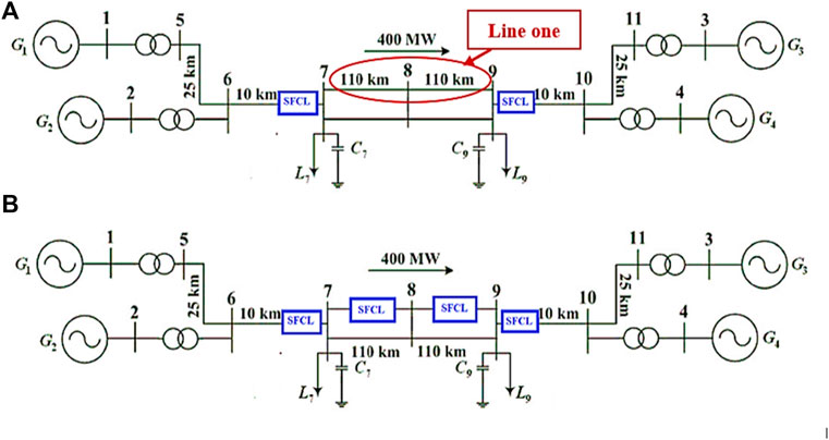
FIGURE 4. Two area system (A) case 1. (B) Case (2).
The short circuit current at bus
where is
Increasing the critical clearing time or angle typically improves angular stability. Critical clearance time for a machine can be improved by avoiding active power changes during faults, according to the swing equation for a synchronous machine.
Where
4 Simulation results and observations
In this section, the system will be tested under different scenarios to verify that the SFCL can not only limit the fault current but also improve the power system’s transient stability without tuning PSSs. Two kinds of PSS have been used: simplified PSS and conventional PSS. The simplified PSS is MB-PSS designed to introduce intermediate phase advance at all oscillation frequencies of interest, compensating for the inherent lag between field excitation and electrical torque (Zheng et al., 2020), (Leiva Roca et al., 2022). Therefore, only six parameters are required to be tuned. In contrast, the conventional PSS uses the measured electrical power and its relationship to shaft speed as an input signal (Leiva Roca et al., 2022), (Wang et al., 2018b).
4.1 Simplified PSS with SFCL
As mentioned in the previous section, the main objective of using SFCL is to minimize the fault current. As shown in Figures 5A, B, using the SFCL help reduce the fault current through the faulted line by 58%, and the fault current shared from area 1 is reduced by more than 50%.
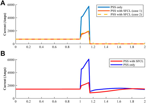
FIGURE 5. (A) The RMS current through the faulted line. (B) Phase-a RMS current with and without SFCL, from area one.
It is well known that PSS is one of the robust solutions to maintain system stability, if it is perfectly tuned, which can be seen in Figures 6–8. However, if the SFCLs are installed in specific locations, the behavior of the power system will be enhanced. For example, Figure 6 shows the active power transferred from B1 to B2 when a severe fault (three phase fault) occurs in the middle of line one. During the fault, the active power drops 210 MW when PSS is only used and when the SFCL installed at the end of each area (case 1) as shown in Figure 4A. However, if the SFCL added also at the end of the faulted line (case 2) as shown in Figure 4B, the active power drops will be less with 160 MW.
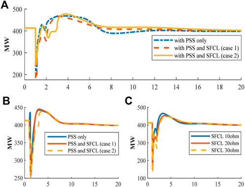
FIGURE 6. (A) Active power transferred from B1 and B2 when a three-phase fault is applied at the middle of line one. (B) Single line to ground fault applied in the middle of line one. (C) Different values of resistance of SFCLs in case 1.
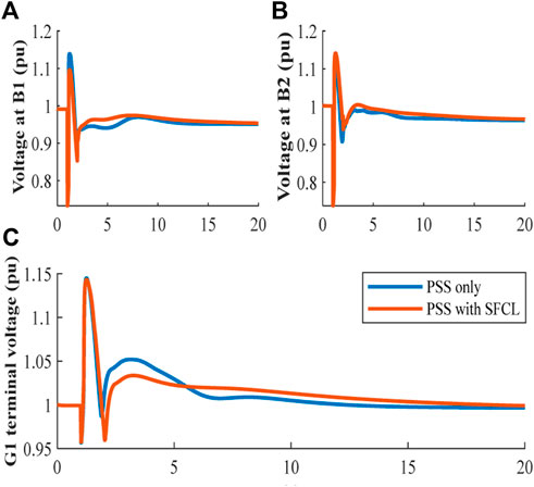
FIGURE 7. (A) The voltage at B1 (pu). (B) The voltage at B2 (pu). (C) G1 terminal voltage (pu).
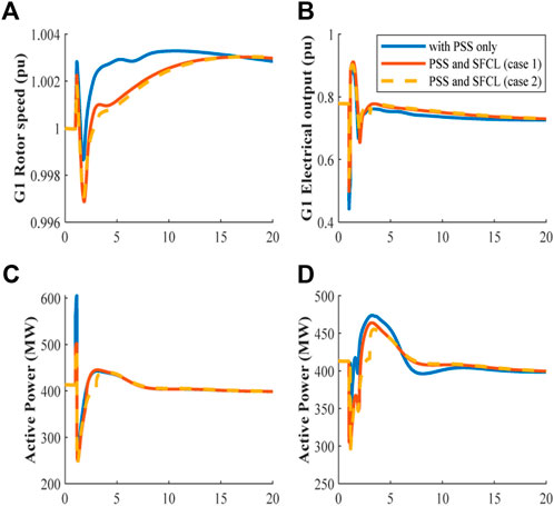
FIGURE 8. (A) G1 rotor speed (pu). (B) Electrical power output from G1 (pu). (C) The system performance when the fault resistance is 80Ω. (D) The system performance when the fault resistance is 10Ω.
For single phase fault in the middle of line one, the active power drops with 130 MW in the case of PSS only used as shown in Figure 6A. While in cases 1 and 2, the active power drops further with 150 MW. In all cases, the system reaches the same steady state as shown in Figure 6B.
The resistance value of the SFCL is important. For instance, Figure 6C illustrates the performance of the active power flow from B1 to B2 when the resistance of the SFCLs changes. It can be seen that when the resistance value increases, there is a further drop in the active power in the event of a three-phase short circuit due to the power loss increasing during the quenching time of the SFCL. Also, increasing the resistance of the SFCL will increase the voltage drop in the grid.
The voltage stability is essential, which needs to be maintained at certain limits before, during, and after the fault. Figures 7A, B show the voltage at B1 and B2, while Figure 7C illustrates the terminal voltage of the G1. From these figures, it can be noticed that voltages drop to new steady-state conditions but are still within ±5% of the nominal. During the fault, the voltage dip is more because the system impedance increases during the disturbance with SFCLs. Nevertheless, once the fault is cleared, the SFCL returns to normal operation, and all buses’ voltages return to a stable state.
During the fault, the impact on the rotor speed of G1 is less when SFCLs are installed in both areas. Non-etheless, after the disturbance is cleared the rotor speed decreases by 0.002 pu lower than the system with only PSSs installed at all units. Then this increases gradually to a new operating point, which is exemplified in Figure 8A. When the disturbance occurs, the frequency rose to 60.18 Hz because the active power is dropped sharply. Once the fault is cleared, the frequency drops to 59.82 Hz, which is the minimum frequency. After that, the system returns to a steady state with a frequency of around 60.18 Hz. Moreover, Figure 8B demonstrates the electrical output power from generator one, which is located in area one, and the impact of using SFCL in desired locations.
The fault resistance can affect the system’s transient performance. The following figures show the system performance when the value of the fault resistance is changed.
Figure 8C displays the active power transferred from B1 to B2 when the three-phase fault is applied at 1s for eight cycles. The fault resistance is 80Ω. Without installing SFCLs, the active power transfer from area1 to area2 increases to 600 MW compared to Figure 6A when the fault resistance is small (0.001Ω). However, if the SFCLs are installed at the proposed locations, as shown in Figure 4, the transient active power will be reduced by 100 MW, which means the stress on the generating units will be decreased. Additionally, if the fault resistance is 10Ω, the active power flow will reach the pre-fault value steadily with the proposed locations as shown in Figure 8D.
The fault location is also crucial in the power system stability study. When the three-phase fault occurs at 20 km away from B2, the system losses synchronism as shown in Figure 9B and without SFCL. Hence, by using SFCLs, the power system’s synchronism can be maintained without any tuning of the PSS. Similarly, when the fault happens 20 km away from B1, the system performance without SFCLs was influenced severely during and after the fault, with a maximum of 500 MW and a minimum of 150 MW. Notably, when the SFCLs are used in both areas, the difference will be reduced to 450 MW at the maximum and 250 MW at the minimum, as shown in Figure 9A. Consequently, the stress on the generators will be restricted.
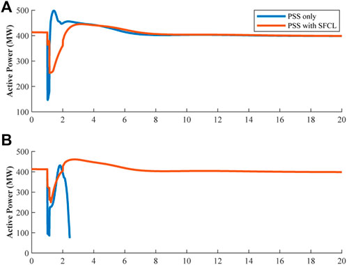
FIGURE 9. (A) The fault is located 20 km away from B1. (B) The fault is located 20 km away from B2.
4.2 Conventional PSS with SFCL
The most crucial point is maintaining the continuity of power flow from B1 to B2. This depends on the severity of the short circuit and the system condition at the time of the fault. In this case, a three-phase fault has been applied in different locations on line 1. Before the fault incident, both transmission lines carried the same active power. However, once line 1 is tripped, the other line must carry the full transferred power from area-1 to area-2. Figure 10A shows the power flow from B1 to B2 when a three-phase short circuit occurs in the middle of line one. The system with only conventional acceleration power delta power system stabilizer (Delta Pa) goes to instability, which means that the synchronism of the grid has been lost. Synchronization failure happens because Delta Pa PSS uses an open loop system. The conventional acceleration power-based- (Delta Pa) PSS is used for damping the small-signal oscillation and is unsuitable for large disturbances. However, with resistive SFCL the system is stable.
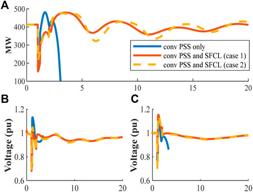
FIGURE 10. (A) Transferred power from B1 to B2, when the fault applied at the middle of the transmission line one. (B) The voltage at B1 (pu). (C) The voltage at B2 (pu).
Figures 10C show the voltages at B1 and B2. It can be seen from the figure that the voltages go into instability after the disturbance. However, if the SFCL is used, the voltages are stable and within the operational limits of ±5% of the nominal value.
Figure 11A demonstrates the rotor speed of generator 1 in area 1. The frequency drops to 59.76 Hz, with a peak value of 60.48 Hz. Finally, the system reaches a steady state at 59.94 Hz. That change in frequency is related to the change in electrical power output from generator 1, which is shown in Figure 11C. While Figure 11B shows the terminal voltage of machine 1 in area 1 as an example, and it is observed that the simulation stopped running for a few seconds after the short circuit happens. This is because the terminal voltage keeps increasing and the active power decreases. Nevertheless, the voltage is closer to the nominal value when the SFCLs were installed (either case 1 or 2).
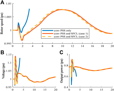
FIGURE 11. (A) G1 rotor speed (pu). (B) The terminal voltage of G1. (C) Electrical power output from G1.
Figure 12A shows that when the disturbance occurs near the receiving end bus, the system will collapse because the Delta Pa PSS uses an open loop system which is unable to maintain the system synchronism under a new highly stressed operating point. However, if the SFCLs are installed in association with the conventional PSS the system will remain synchronized and stable. Figure 12B emphasizes that the SFCLs would improve the power system stability under any condition.
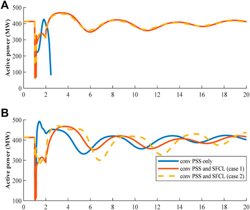
FIGURE 12. (A) Transferred power from B1 to B2, when the fault applied at the 20 km away from B2. (B) Transferred power from B1 to B2, when the fault applied at the 20 km away from B1.
5 SFCL practical application issues
There are still obstacles to the large-scale application of resistive-type SFCL. Although it is compact in structure, simple to implement (directly connected to the transmission line), has no control required, is rapid in response, and has minimal impact on the power grid, it requires a significant number of superconducting tapes (high in cost). In addition, it has higher AC loss generated during the current limiting period. There are still other issues, such as the costly material and production costs, the high cost of low-temperature operation and maintenance, and the operation’s dependability not yet shown. Furthermore, the cryogenic system’s capacity will rise with the number of superconductors. Therefore, the cryogenic system must be inspected and replaced regularly. As a result, cryogenic system stability and extended life expectancy should be necessary for the stable and safe operation of SFCLs.
From a protection point of view, when SFCLs were added to existing electric networks, the amount of the maximum fault current might change, affecting the protection coordination system between protective relays. To examine protection coordination with fault current limiters, the triggering level of the fault current limiters, the installation site, and the amount of impedance caused by the fault current limiter should also be considered.
Despite the superior current limiting capabilities achieved by SFCLs, commercialization and installation of superconducting fault limiters have been delayed due to technical and economic concerns as mentioned above. Table 2 shows three resistive SFCL implemented in England, Germany and Italy.
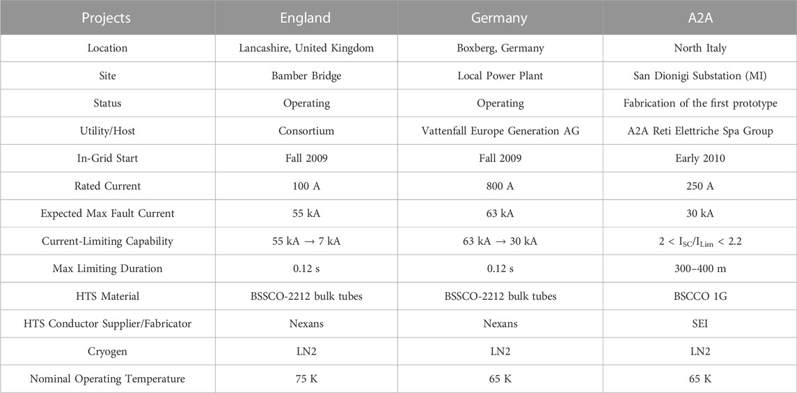
TABLE 2. Resistive SFCL Demonstration Projects [Electric Power Research Institute (EPRI), 2009], (Martini et al., 2014).
6 Fault current techniques within Qatar national grid
The transmission network in Qatar consists of 8 power plants that use natural gas and one PV power plant, and above 400 substations with different voltage levels (400 kV, 220 kV, 132 kV, 66 kV, 33 kV, 22 kV, and 11 kV) (Alashqar et al., 2022). As a result, the transmission and distribution expansion meshed the national grid, and the fault level increased. Figure 13 shows the comparison between 2020 and 2021 subject to the total number of tripping the transmission network, and these tripping due to several reasons such as joint cable failure, protection maloperation, fault in the OHL, third-party damage, etc.,
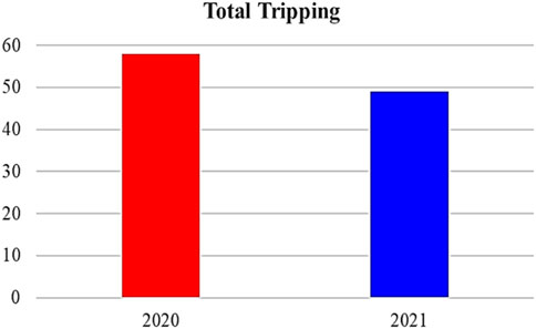
FIGURE 13. Total tripping in the transmission network in 2020 and 2021.
Figures 14, 15 show a real measurement for the system behavior after a phase-phase fault occurred in the 400 kV OHL circuit. The fault happened during the minimum time on 16th January 2021 when the number of running machines was less than the peak in summer. As a result, the system peak on the day of incidence is 50% less compared to the system peak in summer. Figure 14 illustrates that the fault current reached around 23 kA in both phase a and phase b. Also, Figure 15A shows the voltage behavior, and it can be seen clearly that a voltage dip occurred, and the voltage reached 308 kV and normalized within 71 m. Furthermore, as shown in Figure 15B, the system frequency fluctuated to reach around 50.4 Hz maximum and approximately 49.6 Hz minimum.
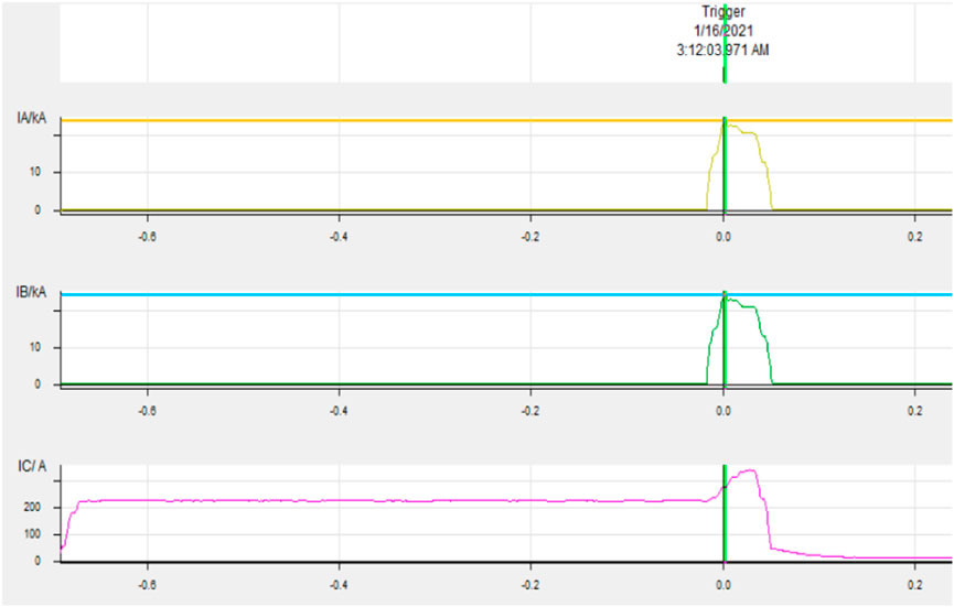
FIGURE 14. Three phase current after phase-to-phase fault occurred.
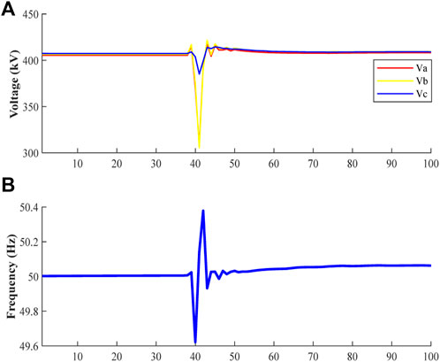
FIGURE 15. (A) Voltage behavior at 400 kV level at one substation, (B) System frequency (readings every 50 ms from PMU).
Traditional techniques are used to limit the fault current, such as splitting busbars, restricting generations in some locations, opening circuits (cable, OHL, and transformers), installing series reactors, and for future generations, high-impedance transformers are required. The SFCL is not preferable from a planning perspective due to the high cost compared to the other solution. For example, the cost of a series reactor in the 400 kV level costs 3.2 M$ (excluding the modification cost in the line), whereas a SFCL unit costs three times the series reactor. However, the SFCL is still developing, and the cost will decline with time.
6 Conclusion
Stability is a great concern of the power system operations, which needs to be maintained under any operating condition. However, the growth in the electricity supply and the sophistication in the electrical networks leads to an increase in fault current levels, threatening the power system stability. Therefore, a SFCL becomes a promising solution to overcome these challenges. This paper shows a comprehensive analysis of the influence of the SFCL in an interconnected power system. The key findings are:
1) The resistive value of the SFCL needs to be adjusted to avoid voltage drop during normal and abnormal operation conditions.
2) The best location for installing SFCL in the interconnected power system is at the end of each area before the tie line.
3) The fault current is reduced, avoiding the upgrade of the electric equipment.
4) The results show that deploying resistive SFCL enhances the system stability without tuning the power system stabilizer (PSS).
Data availability statement
The original contributions presented in the study are included in the article/Supplementary Material, further inquiries can be directed to the corresponding author.
Author contributions
MA, CY, and YX developed the original ideas and prepared the manuscript; ZL, WZ, and X-PZ helped revise the paper.
Conflict of interest
MA was empolyed by the Qatar General Electricity & Water Corporation (KAHRAMAA).
The remaining authors declare that the research was conducted in the absence of any commercial or financial relationships that could be construed as a potential conflict of interest.
Publisher’s note
All claims expressed in this article are solely those of the authors and do not necessarily represent those of their affiliated organizations, or those of the publisher, the editors and the reviewers. Any product that may be evaluated in this article, or claim that may be made by its manufacturer, is not guaranteed or endorsed by the publisher.
References
Alaraifi, S., Moursi, M. S. E., and Zeineldin, H. H. (2013). Optimal allocation of HTS-FCL for power system security and stability Enhancement. IEEE Trans. Power Syst. 28 (4), 4701–4711. doi:10.1109/TPWRS.2013.2273539
Alashqar, M., Xue, Y., Yang, C., and Zhang, X.-P. (2022). Comprehensive economic analysis of PV farm -A case study of Alkarsaah PV farm in Qatar. Front. Energy Res. 10. 987773. doi:10.3389/fenrg.2022.987773
Anderson, P. M., and Fouad, A. A. (2003). Power system control and stability. Second edition. Piscataway, NJ: IEEE Press: Wiley-Interscience.
Baldan, C. A., Shigue, C. Y., Lamas, J. S., and Filho, E. R. (2007). Test results of a superconducting fault current limiter using YBCO Coated conductor. IEEE Trans. Appl. Supercond. 17 (2), 1903–1906. doi:10.1109/TASC.2007.897771
Blair, S. M., Booth, C. D., and Burt, G. M. (2012). Current–time characteristics of resistive superconducting fault current limiters. IEEE Trans. Appl. Supercond. 22 (2), 5600205. doi:10.1109/TASC.2012.2187291
Blair, S. M. (2013). The analysis and application of resistive superconducting fault current limiters in present and future power systems. Glasgow, Scotland: University of Strathclyde, 192.
Chen, L., Chen, H., Yang, J., Shu, Z., He, H., and Shu, X. (2016). Conceptual design of a high-speed electromagnetic switch for a modified flux-coupling-type SFCL and its application in renewable energy system. SpringerPlus 5, 771. doi:10.1186/s40064-016-2347-6
Chen, L., Tu, X., Chen, H., Yang, J., Wu, Y., Shu, X., et al. (2016). Technical evaluation of superconducting fault current limiters used in a Micro-grid by considering the Fault characteristics of distributed generation, energy Storage and power loads. Energies 9 (10), 769. doi:10.3390/en9100769
Egorova, E., Bahirat, H., Mork, D. B. A., Perger, D. W. F., and Holcomb, D. M. (2013). EMTP-ATP modeling of a resistive superconducting fault current limiter. Available at: https://www.ipstconf.org/papers/Proc_IPST2013/13IPST071.pdf.
Electric Power Research Institute (Epri), (2009). Superconducting Fault current limiters, technology watch 2009. Palo Alto, CA: EPRI, 1017793. http://assets.fiercemarkets.net/public/smartgridnews/000000000001017793.pdf (accessed 20, 08, 2019).
Elshiekh, M. E., Mansour, D. A., and Azmy, A. M. (2013). Improving Fault Ride-through capability of DFIG-based Wind Turbine using superconducting fault current limiter. IEEE Trans. Appl. Supercond. 23 (3), 5601204. doi:10.1109/TASC.2012.2235132
Glover, J. D., Overbye, T. J., and Sarma, M. S. (2017). Power system analysis & design. Sixth edition. Boston, MA: Cengage Learning.
Grigsby, L. L. (2012). Power system stability and control [electronic resource]. 3rd ed. (Boca Raton, Fla: CRC Press).
Jain, A., Dubey, V. K., Jawale, G., Mangalvedekar, H. A., and Kanakgiri, K. (2016). “Limiting fault current in a power system network by SFCL: A step input approach,” in 2016 IEEE 6th International Conference on Power Systems (ICPS), New Delhi, India, March 2016 (IEEE), 1–5. doi:10.1109/ICPES.2016.7584095
Kamarposhti, M. A., Shokouhandeh, H., Colak, I., Band, S. S., and Eguchi, K. (2021). Optimal location of FACTS devices in Order to Simultaneously improving transmission losses and stability Margin using artificial Bee Colony algorithm. IEEE Access 9, 125920–125929. doi:10.1109/ACCESS.2021.3108687
Khatibi, M., and Bigdeli, M. (2014). Transient stability improvement of power systems by optimal sizing and allocation of resistive superconducting fault current limiters using Particle. Swarm Optim. 1 (3), 17.
Kodle, S., Padmini, V., Bahirat, H. J., Khaparde, S. A., Lubicki, P., and Dabeer, V. (2016). “Application of Super Conducting fault current limiter in Indian grid,” in 2016 IEEE 6th International Conference on Power Systems (ICPS), New Delhi, India, March 2016 (IEEE), 1–6. doi:10.1109/ICPES.2016.7584226
Kovalsky, L., Xing, Y., Tekletsadik, K., Keri, A., Bock, J., and Breuer, F. (2005). Applications of superconducting fault current limiters in electric power transmission systems. IEEE Trans. Appl. Supercond. 15 (2), 2130–2133. doi:10.1109/TASC.2005.849471
Koyama, T., and Yanabu, S. (2009). Study and development of superconducting fault current limiter with high speed Reclosing. IEEE Trans. Appl. Supercond. 19 (3), 1868–1871. doi:10.1109/TASC.2009.2018783
Kumar, A., Verma, N., and Kumari, S. K. (2016). Application of superconducting fault current limiter in single phase system using Simulink. Imperial J. Interdiscip. Res. 2 (8). Available at: http://www.imperialjournals.com/index.php/IJIR/article/view/1563 (Accessed 25, 06, 2019).
Kundur, P., Paserba, J., Ajjarapu, V., Andersson, G., Bose, A., Canizares, C., et al. (2004). Definition and classification of power system stability IEEE/CIGRE joint task force on stability terms and definitions. IEEE Trans. Power Syst. 19 (3), 1387–1401. doi:10.1109/TPWRS.2004.825981
Lee, B. W., Sim, J., Park, K. B., and Oh, I. S. (2008). Practical application issues of superconducting fault current limiters for electric power systems. IEEE Trans. Appl. Supercond. 18 (2), 620–623. doi:10.1109/TASC.2008.920784
Lee, G.-J. (2011). “Superconductivity application in power system,” in Applications of high-Tc superconductivity (London: IntechOpen). doi:10.5772/16334
Leiva Roca, D. A., Mercado, P., and Suvire, G. (2022). System frequency response model considering the influence of power system stabilizers. IEEE Lat. Am. Trans. 20 (6), 912–920. doi:10.1109/TLA.2022.9757373
Li, B., Li, C., Guo, F., and Xin, Y. (2014). Overcurrent protection coordination in a power distribution network with the active superconductive fault current limiter. IEEE Trans. Appl. Supercond. 24 (5), 1–4. doi:10.1109/TASC.2014.2333811
Lim, S., Kim, J.-S., Moon, J. F., Kim, J.-C., Rhee, S.-B., Kim, C.-H., et al. (2009). Quench and recovery characteristics of a SFCL applied into neutral line of a three-phase power system. IEEE Trans. Appl. Supercond. 19 (3), 1835–1838. doi:10.1109/TASC.2009.2017754
Machowski, J., Bialek, J., and Bumby, D. J. (2008). Power system dynamics: Stability and control. 2nd edition. Chichester, U.K: Wiley-Blackwell.
Martini, L., Bocchi, M., Ascade, M., Valzasina, A., Rossi, V., Ravetta, C., et al. (2014). The first Italian Superconducting Fault Current Limiter: Results of the field testing experience after one year operation. J. Phys. Conf. Ser. 507 (3), 032003. doi:10.1088/1742-6596/507/3/032003
Matsumoto, K. (2010). “General theory of high-Tc superconductors,” in High temperature superconductors. Editors R. Bhattacharya, and M. P. Paranthaman (Weinheim, Germany: Wiley-VCH Verlag GmbH & Co. KGaA), 1–47. doi:10.1002/9783527631049.ch1
Miyashita, M., Umeda, S., Nagao, S., Amemiya, N., Kubota, H., Kudo, Y., et al. (2005). Measurement of lateral current redistribution of fault current limiter using YBCO thin film. IEEE Trans. Appl. Supercond. 15 (2), 2023–2026. doi:10.1109/TASC.2005.849442
Mohamed, E. (2012). “Enhancement of power system transient stability using superconducting fault current limiters with YBCO and Bi-2212,” in The Middle East Power Systems Conference (MEPCON’2012), December 2012 (MEPCON).
Moon, J., Lim, S., Kim, J., and Yun, S. (2011). Assessment of the impact of SFCL on voltage Sags in power distribution system. IEEE Trans. Appl. Supercond. 21 (3), 2161–2164. doi:10.1109/TASC.2010.2093592
Noe, M., and Steurer, M. (2007). High-temperature superconductor fault current limiters: Concepts, applications, and development status. Supercond. Sci. Technol. 20 (3), R15–R29. doi:10.1088/0953-2048/20/3/R01
Pawar, R., and Chavan, P. (2017). Minimizing of fault current using SFCL Technology. Int. J. of Eng. Dev. Res. 5, 1261–1267.
Ravindranath, B., and Chander, M. (1977). Power system protection and switchgear. New Delhi,India: New Age.
Sjostrom, M., Cherkaoui, R., and Dutoit, B. (1999). Enhancement of power system transient stability using superconducting fault current limiters. IEEE Trans. Appl. Supercond. 9 (2), 1328–1330. doi:10.1109/77.783547
Son, G. T., Lee, H., Lee, S., and Park, J. (2012). A study on the Direct stability analysis of Multi-machine power system with resistive SFCL. IEEE Trans. Appl. Supercond. 22 (3), 5602304. doi:10.1109/TASC.2011.2177626
Sung, B. C., Park, D. K., Park, J., and Ko, T. K. (2009). Study on a series resistive SFCL to improve power system transient stability: Modeling, simulation, and Experimental Verification. IEEE Trans. Industrial Electron. 56 (7), 2412–2419. doi:10.1109/TIE.2009.2018432
Vojenčiak, M., Dutoit, B., Šouc, J., and Gömöry, F. (2016). Can resistive-type fault current limiter operate in Cryogen-Free Environment? IEEE Trans. Appl. Supercond. 26 (3), 1–4. doi:10.1109/TASC.2016.2535175
Wang, H., Zhang, J., Niu, X., Tian, B., Hong, H., and Xin, Y. (2014). Electrical Insulation of HTS coils in saturated iron core superconducting fault current limiter. IEEE Trans. Appl. Supercond. 24 (3), 1–4. doi:10.1109/TASC.2013.2290944
Wang, M. H., He, Y. F., Yang, T. B., Jia, Y., and Xu, Z. (2020). Cascaded voltage control for electric Springs with DC-Link film capacitors. IEEE J. Emerg. Sel. Top. Power Electron. 8 (4), 3982–3994. doi:10.1109/jestpe.2019.2962238
Wang, M. H., Mok, K. T., Tan, S. C., and Hui, S. Y. R. (2018). Multifunctional DC electric Springs for improving voltage Quality of DC grids. IEEE Trans. Smart Grid 9 (3), 2248–2258.
Wang, M. H., Yan, S., Tan, S. C., and Hui, S. Y. R. (2018). Hybrid-DC electric Springs for DC voltage regulation and Harmonic Cancellation in DC Microgrids. IEEE Trans. Power Electron. 33 (2), 1167–1177. doi:10.1109/tpel.2017.2681120
Wang, M. H., Yang, T. B., Tan, S. C., and Hui, S. Y. R. (2019). Hybrid electric Springs for grid-tied power control and Storage Reduction in AC Microgrids. IEEE Trans. Power Electron. 34 (4), 3214–3225. doi:10.1109/tpel.2018.2854569
Yang, Q., Blond, S. L., Liang, F., Yuan, W., Zhang, M., and Li, J. (2017). Design and application of superconducting fault current limiter in a Multiterminal HVDC system. IEEE Trans. Appl. Supercond. 27 (4), 1–5. doi:10.1109/TASC.2017.2669152
Yonemura, N., Yamabe, K., Shirai, Y., Kobayashi, S., Nagaishi, T., and Konishi, M. (2015). Current limiting performance of transformer-type superconducting fault current limiter made of BSCCO and REBCO Wires. IEEE Trans. Appl. Supercond. 25 (3), 1–4. doi:10.1109/TASC.2014.2377126
Zhang, X., Ruiz, H. S., Zhong, Z., and Coombs, T. A. (2015). Implementation of resistive type superconducting fault current limiters in electrical grids: Performance analysis and measuring of optimal locations. Available at: http://arxiv.org/abs/1508.01162 (Accessed 18, 06, 2019).
Appendix A1:
The generator parameters used in Figure 4 (the studied system) in per unit are as follows:
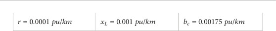
Each step-up transformer has an impedance of
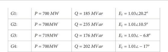
The generating units loaded as follows:
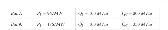
Loads and reactive power supplied by shunt capacitor at bus 7 and bus 9 are as follows:
Keywords: interconnected power system, two-area system, resistive superconductor fault current limiter, fault location, power system dynamic
Citation: Alashqar M, Yang C, Xue Y, Liu Z, Zheng W and Zhang X-P (2023) Enhancing transient stability of power systems using a resistive superconducting fault current limiter. Front. Energy Res. 10:1106836. doi: 10.3389/fenrg.2022.1106836
Received: 24 November 2022; Accepted: 08 December 2022;
Published: 23 January 2023.
Edited by:
Xue Lyu, University of Wisconsin-Madison, United StatesReviewed by:
Yangbin Zeng, Tsinghua University, ChinaSen Zhang, State Grid Jiangsu Electric Power Co., LTD., China
Copyright © 2023 Alashqar, Yang, Xue, Liu, Zheng and Zhang. This is an open-access article distributed under the terms of the Creative Commons Attribution License (CC BY). The use, distribution or reproduction in other forums is permitted, provided the original author(s) and the copyright owner(s) are credited and that the original publication in this journal is cited, in accordance with accepted academic practice. No use, distribution or reproduction is permitted which does not comply with these terms.
*Correspondence: Conghuan Yang, Y29uZ2h1YW55YW5nQGZveG1haWwuY29t