
94% of researchers rate our articles as excellent or good
Learn more about the work of our research integrity team to safeguard the quality of each article we publish.
Find out more
ORIGINAL RESEARCH article
Front. Energy Res. , 04 January 2023
Sec. Process and Energy Systems Engineering
Volume 10 - 2022 | https://doi.org/10.3389/fenrg.2022.1083662
 A. Sivapriya1
 N. Kalaiarasi1
 Pradeep Vishnuram1
 Mohamad Abou Houran2*
 Mohit Bajaj3,4
 Mukesh Pushkarna5
 Salah Kamel6,7*
Multilevel inverters (MLI) are finding widespread in various engineering and commercial applications owing to their immense performance. The cascaded H-bridge (CHB) inverter is the most potential MLI topology for renewable energy applications. The successful operation of the CHB-MLI depends on the integrity of the semiconductor devices and capacitors. Irrespective of its benefits the huge number of switches decreases the reliability of the inverter. Concerning reliability, this article proposes a fault-tolerant (FT) CHB MLI for solar photovoltaic applications. The proposed CHB MLI can withstand both the single and multiple open circuit faults in all the H-bridges of the CHB topology. The diagonally opposite switch pairs of CHB topology have similar fault features which lead to difficulty in finding the fault switches using the analytical fault diagnosis methods. Hence an artificial intelligence (AI) based fault diagnosis (FD) and FT operation of CHB MLI are interpreted. The proposed model offers complete FD and FT operation within one fundamental cycle which is advantageous relative to the existing methods. Compared to the existing methods, the proposed AI-based fault diagnosis strategy achieves a shorter diagnosis time and provides 96% classification accuracy between various fault conditions. Further, the simulation and HIL results demonstrated that the voltage magnitude and THD have been maintained at 8.24% before and after the fault state. In addition, the suggested FT structure ensures the constant output power over the post-fault operation for both single and multiple switch failure instances while improving the MLI resilience. The feasibility and performance of the proposed method have been investigated through related case studies using simulation and hardware-in-the-loop (HIL) tests on a single-phase fifteen-level CHB MLI.
CHB MLI is the most desired MLI topology employed in diversified applications due to its remarkable features like modularity, scalability, and controllability. To attain the staircase voltage waveform, the CHB MLI comprises many series-connected h-bridge cells that enable low-voltage, fast-power switches, such as insulated-gate bipolar transistors (IGBT). The CHB MLI is divided into two topologies based on the structure: symmetric and asymmetric. When using symmetric CHB MLI, the input voltage magnitude for each module is identical; however, when using asymmetric CHB MLI, the voltage magnitude of the input voltage source is different. Symmetric CHB (SCHB) has garnered more attention than asymmetric CHB (ACHB) owing to its modular construction, low-rating power devices, and separated dc voltage sources, which make it more appropriate and efficient for solar PV conversion systems. However, the increased number of power switches in an SCHB increases the possibility of switch faults. A recent survey and research on over 200 products from 80 firms state that 34% of faults can occur in semiconductor switches and solders (Siddique et al., 2019). The switch faults are classified into open circuit faults (OCF) and short circuit faults (SCF), the most prevalent fault in inverters. OCF does not cause an immediate shutdown, but in the long term causes the linked components to fail, leading to a shutdown. The switch failure greatly influences the reliability of the MLI, which is a significant concern in an MLI. Major applications such as adjustable speed drives, battery management systems, solar systems, and grid-connected systems demand an uninterrupted, continuous, and protected mode of operation. For such kinds of applications, fault-tolerant inverters are extremely crucial to maintain the reliability and safety of the system. For uninterrupted service, fault-tolerant control is utilized to keep the load’s power balanced at all times and restore normal operation. This substantiates the need to include fault tolerance in the design process of multilevel inverters. Thus, MLI fault tolerance has inspired extensive study in recent research (Siva Priya and Kalaiarasi, 2022).
Consequently, it is necessary to detect any faults that may exist with the switching parts of the inverter. In addition to FD, fault-tolerant control (FTC) of the CHB MLI is also required in the event of a faulty condition to restore the system to its pre-fault state as quickly as feasible. Thus, an MLI system with FD and fault tolerance management is paramount for increasing the reliability of the MLI. In (Kumar et al., 2020), a rapid FD system focusing on estimating each module’s active and zero voltage states is presented. However, this approach does not work with symmetric CHB MLI. The OCF in symmetric CHB MLI can be identified by collecting fault characteristics from the primary component, such as total harmonic distortion (THD), mean value, and RMS value (Sharma et al., 2021). Yet, this approach requires different measurements, which raises the system’s cost. However, the FD mentioned above cannot identify multiple switch faults or even employ a more significant number of indicators to identify a single switch (SS) fault. Faulty phases can be identified in (Mehta et al., 2018), utilizing THD and the normalization factor of output current. Furthermore, this technique is not suited for single-phase CHB MLI. However, accurate measurement circuits and high-speed processors are required instantly to detect and calculate THD.
Also, the CHB MLI in (Gireesh Kumar et al., 2022), (Choudhury et al., 2021) utilizes several classifier algorithms, heuristic approaches, and statistical feature optimization techniques for FD. However, these approaches have higher computational complexity and high-speed processors and need more rigorous classifier training, resulting in a longer detection time. Simple and highly effective soft computing techniques, such as "ANN, Machine learning, and Deep learning,” are now widely utilized to address the aforementioned constraints. These methods are quick, precise, and accurate for switch fault detection. Artificial intelligence (AI) is becoming widespread in power electronic component fault detection with the advent of powerful and low-cost microcontrollers. Although several studies have been conducted on FD in CHB MLI, few studies have concentrated on reduced switch topologies. In (Raj et al., 2018a), an intelligent FD approach is deployed to locate single switch gate drive faults on CHB MLI. The FD using two distinct machine learning (ML) algorithms, SVM and kNN, is suggested (Ali et al., 2021), with the PPCA-SVM-based ML algorithms providing the most accurate and efficient fault detection. Moreover, the approaches presented in (Raj et al., 2018a), (Ali et al., 2021) give SS fault detection in CHB MLI and do not address the faults in multiple switches. The mathematical model for a three-phase inverter employing phase current-based fault detection technique is described in (Cheng et al., 2020a) to find OCF in single and various switches. Although this method takes a long time to implement, it does not provide an exact location of the fault. In (Kuraku et al., 2019), a fuzzy-based fault detection approach is presented to identify single and multiple switch faults in motor drives. The phase current of the drive is employed as a fault identification characteristic; nevertheless, the absence of a systematic methodology and slower reaction are the fundamental limitations of fuzzy logic-based fault detection. Despite fault detection, locating the exact location of the fault in diagonal pairs of switches in CHB MLI is challenging due to the identical fault features. Therefore, there is still a lack of studies in determining the exact location of faulty switches in multiple fault scenarios.
Further, the MLI system with the FTC scheme is inevitable to provide a complete fault diagnosis approach. The FTC approaches are divided into two classes, hardware-based and software-based implementations. In hardware-based solutions, additional elements are provided to the inverter to mitigate the faults. In software-based techniques, the regulation and modulation of the MLI are adjusted to maintain the maximum voltage of the inverter in the event of a fault. Using a modified level-shifted pulse width modulation (PWM) approach with neutral shift (NS) (Kim et al., 2016) reconfigures the switching strategy of the inverter by effectively utilizing the remaining healthy switch in a defective module to keep the three-phase balanced line-to-line voltage constant under fault. Modifying the amplitude and angle of phase voltages in the inverter creates proportional line voltages with balanced stress on all healthy units. However, this method is confined to the number of voltage levels and types of faults. Instead of skipping a faulty cell (Ouni et al., 2019), suggests that it can be utilized to generate voltage using a phase-shifting (PS) PWM technique with fewer levels. On the other hand, this technique only works with PS PWM and increases the switching stress of different devices, making them more prone to failure. Extensive mathematical calculations, the lower voltage at the output, voltage fluctuations in the system, restricted to higher voltage levels, and difficulty using closed-loop applications are some of the constraints of the software-based method.
In (Asif et al., 2021), a new 5-level asymmetric inverter architecture employing the nearest level control (NLC) technique is presented. Using redundant switching states, single-switch open circuit fault-tolerant control is achieved. To enable redundant switching combinations, three auxiliary switches are added. However, the system is unable to tolerate faults on the main switches. The voltage control range of the CHB MLI is widened using a hybridized PWM approach, as described in (Sarwar et al., 2021), and the system is made fault-tolerant by adding two unidirectional switches to withstand SS fault. A hybrid control scheme for CHB MLI employing the half-bridge recombination method was suggested in (Yang et al., 2021) and included the reconfiguration of the modulation method, module reconfiguration, and zero sequence voltage injection for single and double switch failures. However, under a fault scenario, the inverter’s voltage magnitude decreases. Therefore, the topologies presented in (Asif et al., 2021)– (Yang et al., 2021) cannot mitigate fault in multiple switches and provide only a reduced output voltage, raising harmonic distortion and losses under faulty conditions. The FD and FTC structures outlined above encounter the following issues and constraints. Inaccuracy in detecting simultaneous faults in multiple switches, inability to tolerate faults in multiple switches with sustained output power and voltage levels, the significant increase in harmonics, and use of bidirectional switches, which increase the losses and total cost of the system. Therefore, enhancing the reliability of MLI systems and lowering possible risks in the power conversion systems requires efficient fault detection, classification, and fault tolerance.
The literature study highlights the need for further research into the development of a robust fault-tolerant control scheme for the inverter by highlighting the limits and downfalls of existing fault diagnostic techniques. The motivation for the proposed research is summarised below.
1) Despite fault detection, identifying the exact location of the fault in diagonal pairs of switches of CHB MLI is challenging due to the identical fault features. Therefore, there is still a lack of studies in determining the exact location of faulty switches in multiple fault scenarios.
2) The inaccuracy in detecting simultaneous faults in multiple switches hampers the performance of the fault diagnosis scheme which may result in the wrong diagnosis and delayed reconfiguration.
3) The existing FTC scheme finds limitations in tolerating single and multiple faults with preserved output voltage and current at post-fault conditions.
4) The severity of the fault varies significantly with the types of faults, fault location, and operating conditions. Thus, the fault diagnosis scheme should be able to detect, classify and tolerate the fault quickly under all possible fault scenarios.
A survey of the relevant literature finds various shortcomings in the currently used traditional model-based approach, signal processing, and metaheuristic method for MLIs. In addition, there is a lack of robust fault tolerance in present methods for both single and double switches. Most fault-tolerant solutions lack thorough performance evaluations of pre- and post-fault operations with varying fault types. Additionally, optimization and transformation methods are needed for fault diagnosis, and the performance of the current signal processing methodology is diminished in the presence of noise in the sampled signals. The limitations of previous research methods and current diagnostic methods are discussed in this article. The contributions of AI-based fault detection and diagnosis approach are outlined here.
1) This article aims to develop the ANN approach for CHB MLI fault diagnosis that utilizes multilayer perceptron (MLP) to detect open circuit faults and their classification.
2) The proposed scheme can detect single and multiple OC faults with an extensive disparity in fault types, locations, and operating conditions.
3) The proposed MLP-based technique requires only a voltage signal as a fault diagnostic feature which reduces the complexity of the fault detection system.
4) The proposed FTC scheme maintains the output voltage and current at the same level as normal, which is widely needed for critical load or solar PV-based grid-connected applications.
5) The proposed hardware-based FTC scheme addresses the challenges faced by the existing schemes, including reduced output voltage at post-fault operation, increased harmonics, low detection rate among multiple faults, and low reliability.
6) The proposed MLP-FD technique has high detection accuracy of 96% among various single and multiple switch OC faults. Also, it requires only about 10 ms and 20 ms to clear the single and multiple OC faults, which is less than one fundamental cycle.
Furthermore, the structure of this article is as follows: Section 2 presents the system configuration of CHB MLI and analysis of various OCF conditions; Section 3 explicates the proposed fault diagnostic strategy based on ANN; Section 4 emphasizes the simulation and HIL results and discussions to assess the performances of fault detection and fault tolerant approaches; Section 5 provides a comparison with existing works, and Section 6 draws the conclusion.
In CHB MLI, h-bridge and low-voltage dc power sources work together to provide higher or lowered power levels by adding or removing h-bridge modules. Each h-bridge unit is configured to produce three distinct output voltages, +Vdc, 0Vdc, and -Vdc, by connecting the dc supply to the load through various switch configurations. Figure 1A depicts the general structure of the CHB MLI as including (2n+1) h-bridges, where n represents the number of h-bridges. Each h-bridge unit consists of four semiconductor switching devices (S1-S4) coupled to antiparallel diodes and separate dc voltage sources. In this work, a 15-level inverter (n = 7) with a dc voltage of magnitude Vdc1 = Vdc2 = Vdc = 48 V and an RL load of 100Ω and 30 mH is examined for fault diagnosis. At standard conditions, the 15-level output voltage appears across the load as +7Vdc, 0V, and -7Vdc with a peak voltage of 336 V. The categories of OCF are classified based on the fault level and magnitude and are grouped into similar groups as shown in Figure 1B. The PD PWM technique is used to generate the switching patterns of the proposed CHB MLI by comparing the triangular carrier signal with the sinusoidal reference signal, as illustrated in Figure 2. The general expression for output voltage is given as
where V1, V2 … Vn is the output voltage of each h-bridge.
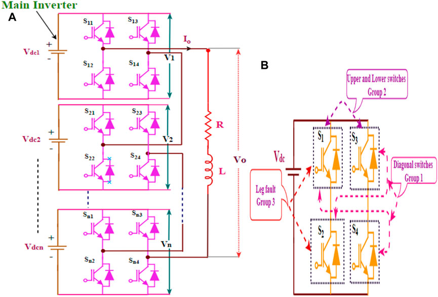
FIGURE 1. (A) Schematic structure of single-phase 15-level CHB MLI, (B) Categories of faulty switch pairs.
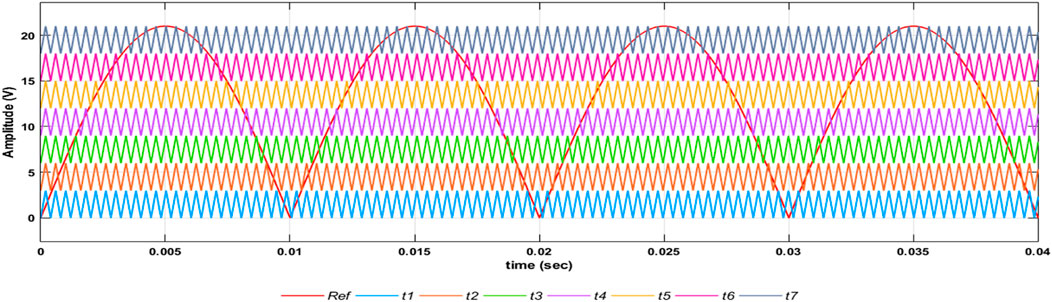
FIGURE 2. PD-PWM implementation Figure.
In this work, the OCFs are emulated as the breakdown of the switch, including the freewheeling diode. The repetition of switching faults that occur at a particular time determines the different kinds of OCF in an MLI. Accordingly, the OCF is classified into the single switch (SS) fault and the double switch (DS) fault. In an instant, the possibilities of switch breakdown are minimal. Thus, the maximum single and double-switch OCFs are examined here. The selection of an appropriate signal for fault detection is essential, which directly impacts fault diagnosis performance. The inverter output voltage includes valuable information to diagnose the fault type and location. The inverter output current signal depends on load variations, but the voltage signals are unaffected by these variations. Therefore, this work utilizes only the inverter output voltage signals for fault diagnosis. For fault classification, the OCFs of CHB MLI are classified into four categories, based on the number and location of faulty switches as shown in Figure 3. The SS fault belongs to fault class-I, and the DS fault belongs to fault class II-IV, a total of four classes. Further, this section analyses the various fault classes and their profound impacts on the CHB MLI output voltage.
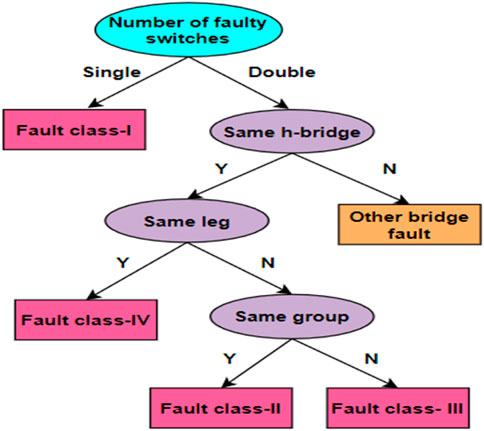
FIGURE 3. Classification of open circuit faults.
• Fault class-I: Single switch fault: When OCF occurs at single switch S1 to S28 the peak voltage reduction in either positive or negative voltage levels with respect to the switch position. Thus, the average peak voltage gets reduced to 288 V.
• The DS fault on the CHB MLI affects the load voltage and leads to variable output voltage waveform with reduced voltage levels. These faults are considered complicated faults in this work. The possibilities of double switch fault cases in the main inverter are classified into three separate fault classes.
• Fault class-II: Failure of diagonal switches: Consider the switches S1 and S4 or S2 and S3 are open-circuited, the peak voltage is reduced to 240 V. The DS fault causes un-symmetry in the output voltage waveform.
• Fault class-III: Failure of upper/lower switches: When the switches S1 and S3 or S2 and S4 are open-circuited, the peak voltage is reduced to 288 V in both the half cycle. Even though the two voltage levels are missing, the voltage waveform is still symmetrical.
• Fault class-IV: Failure of leg: Compared with the other types of OCF, the failure of switches in the same leg nullifies the output voltage. Thus, it can be inferred from the analysis that the output voltage waveform of diagonal switches, upper and lower switches, and leg switches exhibit similar fault characteristics. Hence, they are categorized into three groups.
Further, these fault states and their implications hold for other h-bridges in the main inverter and the output voltage follows the same pattern as S11, S12, S13, and S14. Hence, these voltage patterns can be utilized to identify a faulty switch. Therefore, the fault diagnosis system has extracted the static fault features such as RMS voltage, h-bridge voltage, and the voltage across switch pairs under normal and faulty conditions. Equations 2 to 4 have been used to calculate the deviations in the output voltage, bridge voltage, and voltage across switch pairs.
The deviation in the output voltage of MLI is given by
Similarly, the deviations in the output voltage of the h-bridge are expressed by
The voltage reduction in switch pairs’ is calculated as
m = voltage across switch pairs
Based on the rate of changing these quantities, the faulty h-bridge unit and its faulty switch pairs are precisely detected and classified.
ANN simulates the human brain conceptually and is widely utilized in several decision-making applications. The ANN has three layers and each layer has several neurons interconnected through appropriate weights and bias. Figure 4 depicts the overall block diagram of the proposed FD and fault-tolerant control of CHB MLI. First, the fault features such as output voltage, individual h-bridge voltage, and the voltage across switch pairs are collected from the simulation results and provided as input to the fault diagnostic system. The proposed fault diagnostic method employs a fully connected feedforward NN called multilayer perceptron to identify and classify the normal and faulty conditions of CHB MLI. Multilayer Perceptron comprises an input layer, one or more hidden layers, and an output layer, as shown in Figure 5. The input layer transmits the input signals in a forward direction, distributed to each neuron in the hidden layer. The architecture of the proposed feedforward MLP has two hidden layers and is trained using the provided database. Based on the complexity of the fault, the hidden layers are selected. However, using too many hidden layers results in an overfitting issue since they work well for the training dataset but adversely for the validation dataset.
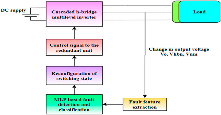
FIGURE 4. Block diagram of the fault diagnostic system.
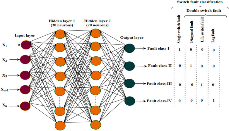
FIGURE 5. Typical MLP structure for fault classification.
Thus, the maximum of two hidden layers is chosen; adding more than two hidden layers has no noticeable influence on network accuracy (Maher et al., 2021). The proposed MLP structure has 22 input neurons, two hidden layers with 30 and 20 neurons where the 22 input neurons correspond to the 22 input features extracted from h-bridge output voltage at normal and different OCF cases. The datasets are collected for both normal and fault conditions, and in the total available dataset, 70% of data are used for training and 30% for testing and validation. The Levenberg-Marquardt backpropagation algorithm trains the neural network. Backpropagation is a supervised learning method used by MLP. Using conjugate gradient algorithms, the MLP is trained by backpropagating errors between desired values known as targets and the network’s output. The MLP with sigmoid hidden neurons and softmax output neurons are used to train the network model. First, the NN assumes the initial weight values Wij, calculates the error between the output and targets, and updates the weight values until minimum MSE reaches. The performance indices of the developed NN are assessed by correlation coefficient R) and mean squared error (MSE).
The flowchart of the proposed MLP-based fault detection and tolerance system has shown in Figure 6. Initially, the MLP is trained with the normal and faulty dataset, and then the trained NN is used for fault detection. The datasets are derived from simulation results under several OCF conditions, including diagonal switch fault, upper/lower switch fault, and leg fault. Four different combinations of OCF are considered for fault detection, classification, and fault-tolerant operations. Nearly 656 datasets are extracted of which 459 are chosen for training, and the rest 197 are used for testing and validation. The dotted line in Figure 6 indicates the operation performed by NN. Initially, the overall output voltage, output voltages of the individual h-bridge unit, and voltage across switch pairs are measured. The controller performs a normal operation if the actual value equals the reference value. If the measured value differs from the reference value indicates the fault mode. In this mode, the controller will calculate the change in the h-bridge voltage (∆Vhbn) and detects the faulty h-bridge. Moreover, after detecting the faulty h-bridge unit, the proposed fault classifier algorithm determines the fault classes based on the number and location of faulty switches as described in Figure 5. Once the fault is detected and classified, the fault-tolerant control mode is initiated by the MLP-NN. The intelligent controller directs the control signal to turn on the redundant unit through A1 and A2 to compensate for the missing voltage level.
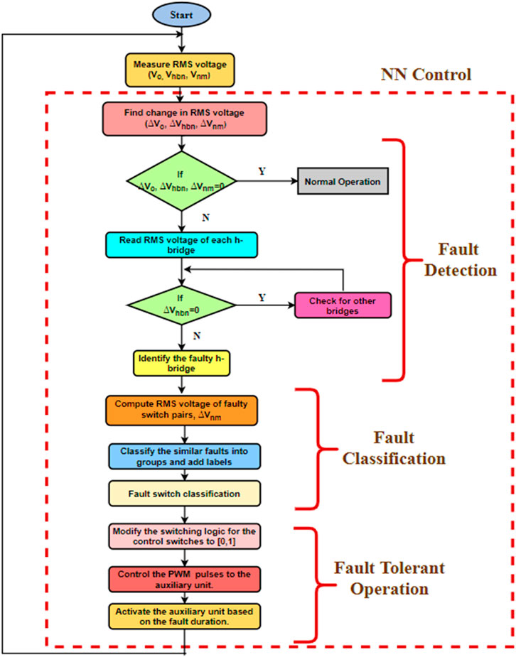
FIGURE 6. Flowchart of the ANN-based fault detection, classification, and fault tolerant control scheme.
For the proposed fault detection and classification process, 22 input parameters (14 voltage across switch pairs (Vnm), seven individual bridge voltage output (Vhbn), and overall output voltage (Vo)) are extracted as fault features and are fed as input to the neural network for various modulation index respectively. All four categories of OCF cases and no-fault conditions have been considered in developing the data set. The target label for the fault diagnosis is presented as a binary classification using the values 0 and 1, which indicate whether the fault has occurred or not. During the fault classification process, the processed fault data are labelled for their respective faults and trained using the fault detection and classification algorithm. The four output neurons represent the SS fault and DS fault, as illustrated in Figure 5. The proposed fault classifier algorithm accurately classifies the four possible categories of OCF.
The analysis of CHB MLI under faulty conditions shows that the function of CHB MLI is unstable, and specific output levels are discarded depending on the fault type, location, and intensity. To address this issue, a revolutionary architecture has been developed in this work to compensate for different sorts of failures while preserving output power ratings and inverter levels at the same time. Figure 7 depicts the circuit configuration for the proposed FT CHB architecture. The proposed design has two major sections the main inverter unit and the redundant h-bridge (R-HB) unit. The redundant h-bridge (R-HB) unit is coupled to the main inverter to compensate for the different forms of OCFs in the CHB MLI. The control of the R-HB unit is provided by the control switches A1 and A2 through the NN controller. The utilization of the R-HB unit creates several additional pathways for generating fifteen-level output voltage. During a fault, the NN controller detects the change in the output voltage, and the FD block displays the present fault status. The fault state is indicated by 1, which represents the faulty switch and associated fault classes. The remaining states are indicated as 0. During normal operation, the control switches [1,0] logic generates the standard output voltage waveform. When fault occurs, the controller initiates the R-HB unit to operate for compensating voltage reduction and missing voltage levels by setting the control logic to [0,1].
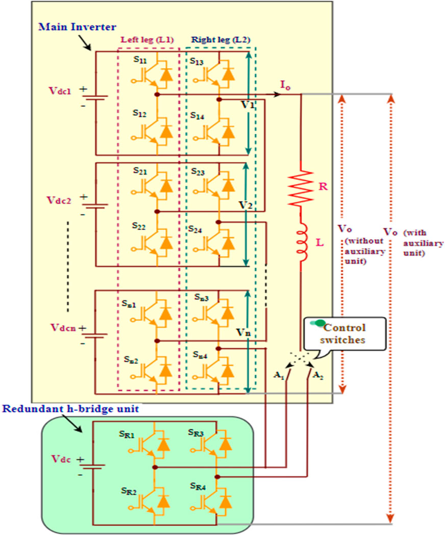
FIGURE 7. Schematic diagram of the proposed fault tolerant control scheme.
To verify the effectiveness of the proposed fault detection and fault tolerant control scheme for single phase fifteen level CHB MLI through simulation and hardware-in-loop (HIL) results are provided for different case studies. The simulation parameters are listed in Table 1. To validate the proposed FD and FTC scheme, the system is tested with four different OCF conditions including SS fault, DS fault in diagonal switches, DS fault in upper and lower switches, and DS fault in the same leg. The simulation and HIL results elucidate the performance of the proposed fault-tolerant inverter in normal, fault, and fault-tolerant modes.
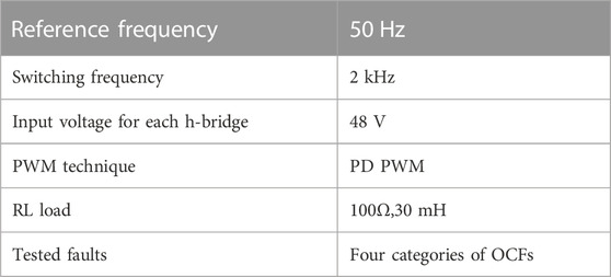
TABLE 1. Simulation parameters.
To investigate the three modes of operation, ten cycles of the output voltage for each state are acquired from t = 0–0.2 s. Figures 8–11 illustrate the simulation results regarding fault detection and fault tolerant operation of the inverter in the OCF condition case switch S11 to S14. The simulation waveform includes the output voltage Vo, bridge voltage V1, fault signal, fault detection signal, and R-HB voltage signal.
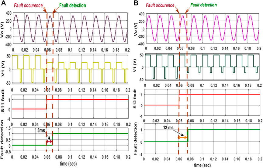
FIGURE 8. Simulation results of single phase fifteen-level CHB MLI under SS OCF at (A) S11, and (B) S12.
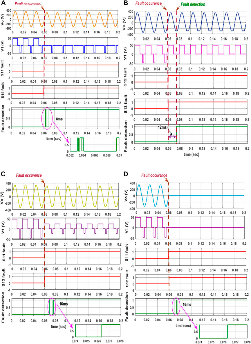
FIGURE 9. Simulation results of single phase fifteen level CHB MLI under DS OCF at (A) S11,S14 (B) S12,S13 (C) S11,S13 (D) S11,S12.
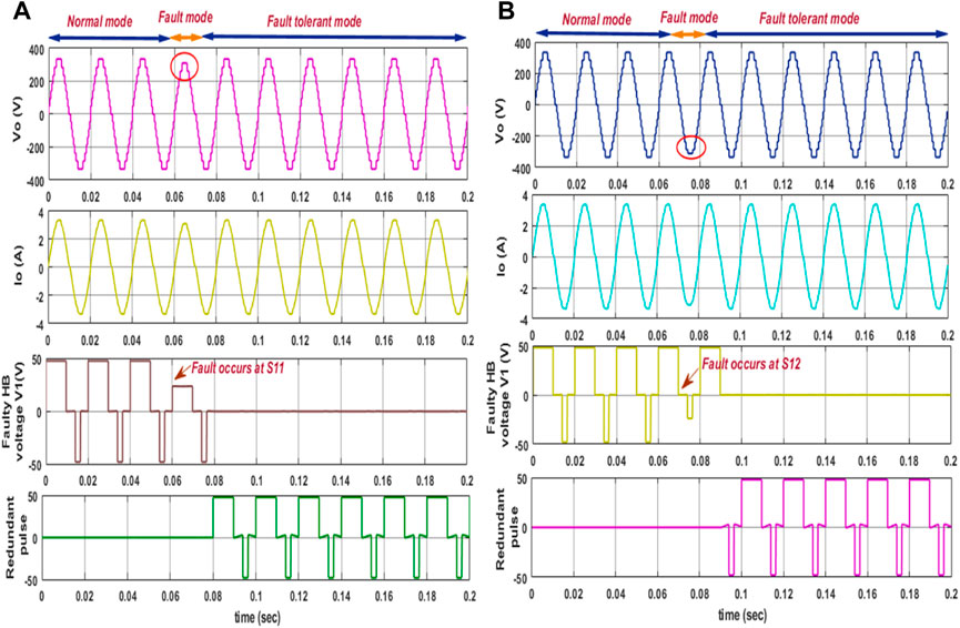
FIGURE 10. Simulation results of fifteen-level CHB MLI under normal, fault, and fault-tolerant mode of SS fault at (A) S11, (B) S12.
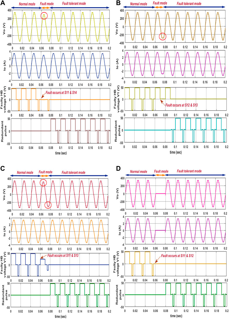
FIGURE 11. Simulation results of fifteen-level CHB MLI under normal, fault, and fault-tolerant mode of DS fault at (A) S11,S14 (B) S12,S13 (C) S11,S13 (D) S11,S12.
Before applying the fault, the system operates normally and the fault signal equals 0. After the occurrence of a fault, the faulty switch is indicated by raising the edge of the fault detection signal from 0 to 1 as shown in Figure 8. When SS occurs at .06 s, the fault detection signal rises to 1, confirming that the fault has occurred at switches. Since the diagonal switches exhibit the same fault characteristics, the fault detection time for switch faults S11 and S14 remains the same at 8 ms and for diagonal switches S12 and S13 at 12 ms, as shown in Figures 8A, B. Only data pertaining to inverter performance under an OCF event for selective switches are provided to avoid similar and repetitive results. When a double switch fault occurs at diagonal pair of switches, the fault signal gives rise to 1 at eight and 12 ms, as illustrated in Figures 9A, B. For all other DS fault conditions, the fault signal is detected within 16 ms to clear the fault, as shown in Figures 9C, D. Similarly, the fault detection results were obtained for all other switches in the CHB MLI. Also, we can see that the time taken to identify all the single switch faults is around only 8 ms and double switch faults at 16 ms. Thus, the variation in fault detection time is based on the corresponding switching states.
The fault-tolerant operation of the CHB MLI begins once the faulty switch is identified. The proposed fault-tolerant control has been implemented by adding the redundant HB (R-HB) unit to the main inverter unit at the time of fault occurrence. The activation of the R-HB unit is controlled by the two control switches A1 and A2. The R-HB unit employs the same gate driver circuit to restore the normal condition. Consequently, the suggested work does not need an extra gate driver circuit. The suggested fault diagnosis approach utilizes just (N+1)/2 sensors instead of 2(N-1) sensors needed for a single-phase N-level CHB MLI. A detailed simulation analysis was carried out under different OCF situations to confirm the feasibility of the envisioned fault tolerant operation as depicted in Figures 10, 11. In normal operating conditions, the inverter produces 15 levels of output voltage from the period 0 to .06 (Normal mode). When SS fault occurs at S11, the inverter output voltage will get reduced in the positive half cycle, and the R- HB unit will get turned on to compensate for the missing voltage level (Fault tolerant mode) as depicted in Figure 10A. Similarly, when an OCF fault occurs at switch S12, the inverter output voltage will get reduced in the negative half cycle, and the controller operates in fault-tolerant mode, as seen in Figure 10B. This condition is valid for all the other SS fault conditions in the CHB MLI. The switch pair S11, S14, and S12, S13 is one of the main switches to create both positive and negative voltage levels; if it fails, both the positive and negative voltage levels generated by HB-1 are eradicated. When these switches fail, the NN controller initiates the command signal to the R-HB unit to compensate for the missing voltage levels, as deployed in Figures 11A, B. Figure 11C displays the simulation results for the fault-tolerant operation of upper switch OCF, S11, and S13. Once the upper switch fault is detected, the NN controller sends the command signal to the R-HB unit to tolerate the missing voltage levels. When leg fault occurs at switches S11 and S12, only zero output voltage is generated, which is unacceptable. Once the leg fault is detected, the controller sends the command signal to turn on the R-HB unit via control switches A1 and A2 to tolerate the fault condition. Figure 11D illustrates the fault-tolerant operation for the faulty inverter leg.
Therefore, in all the SS and DS fault conditions, the post-fault output voltage and current are maintained at the pre-fault level, showing the feasibility of the proposed fault-tolerant MLI. It is noteworthy that the presented fault-tolerant technique, based on the proposed structure, is applicable for n-level configuration. For the fault mentioned above, the controller can detect and tolerate the single and double switch faults in a single h-bridge at a time. Multiple h-bridge faults and variations in load were not investigated. The pre-fault output voltage for fifteen-level FT CHB MLI is 336 V peak to peak (237Vrms) at the frequency of 50 Hz with voltage THD and current THD of 8.24% and 5.84% respectively. Table 2 shows the results of THD calculations utilizing FFT analysis performed during fault and post-operations. Figures 12A, B further demonstrates that the suggested intelligence controller greatly reduces harmonics at the post-fault output voltage. Furthermore, it is clear from the simulation results that the fault occurrence at .06 s and the fault tolerant control operation takes place at .08 s without any compromise with the performance of the inverter. The simulation results show that the time between fault occurrence and fault tolerant control is only about 8 ms for SS fault and 16 ms for DS fault cases. i.e., it takes less than one fundamental cycle to clear both single and DS faults. Also, the THD maintains the same level before and after the occurrence of SS and DS faults. Thus, the inference that can be drawn about the proposed design is that it is possible to achieve perfect fault tolerance for both SS and DS-OCF cases in less than 16 milliseconds. The suggested ANN-based FTC method is easier to implement and requires less time to diagnose faults. Thus, the proposed fault diagnosis method is applicable to generalized inverter structures. The effectiveness of the output voltage, current, and THD maintains the same level before and after the fault, as portrayed in Figures 10–12.
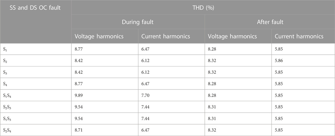
TABLE 2. Harmonic analysis of output voltage at various fault conditions.
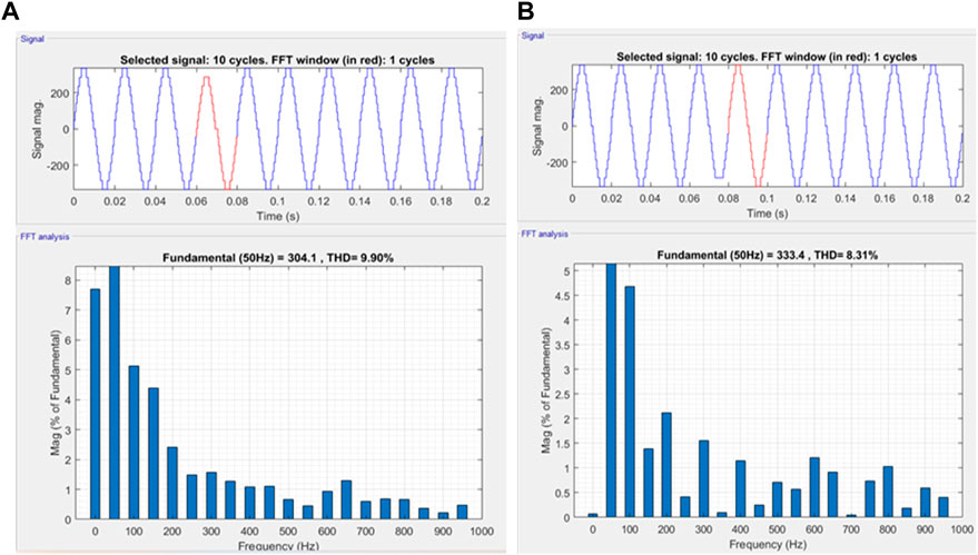
FIGURE 12. Illustration of the output voltage waveform and the corresponding FFT analysis during fault and post-fault condition (A) S1 and S4 fault (B) S2 and S3 fault.
The HIL configuration for real-time simulation is shown in Figure 13. The single phase 15-level CHB MLI utilizing the PDPWM technique with ANN controller is built into the RT lab simulation and dumped into the OP4510 real-time HIL simulator to test the system’s performance. Figures 14, 15 show the real-time HIL results of the proposed fault tolerant control scheme under various OCF conditions.
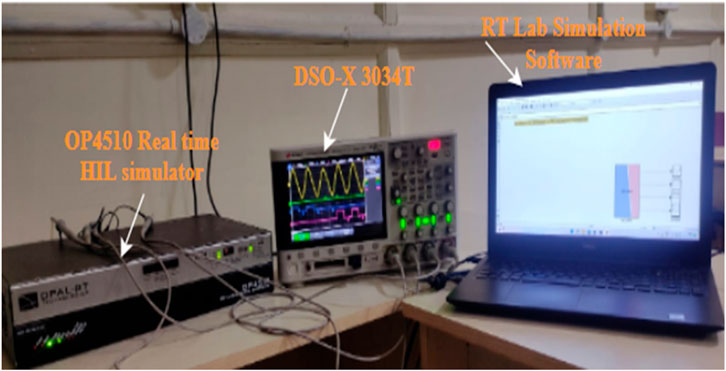
FIGURE 13. Real-time HIL test setup.
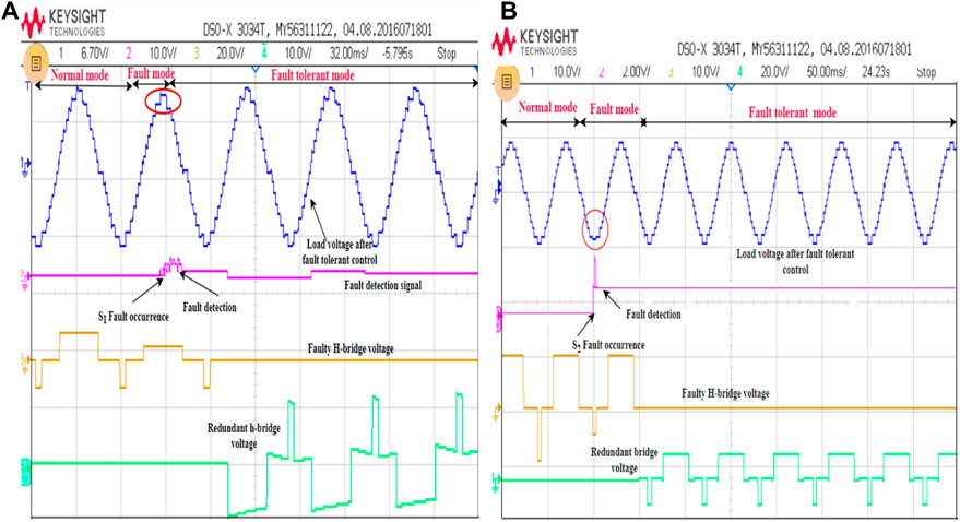
FIGURE 14. HIL results of fifteen-level CHB MLI under SS fault at (A) S11, and (B) S12.
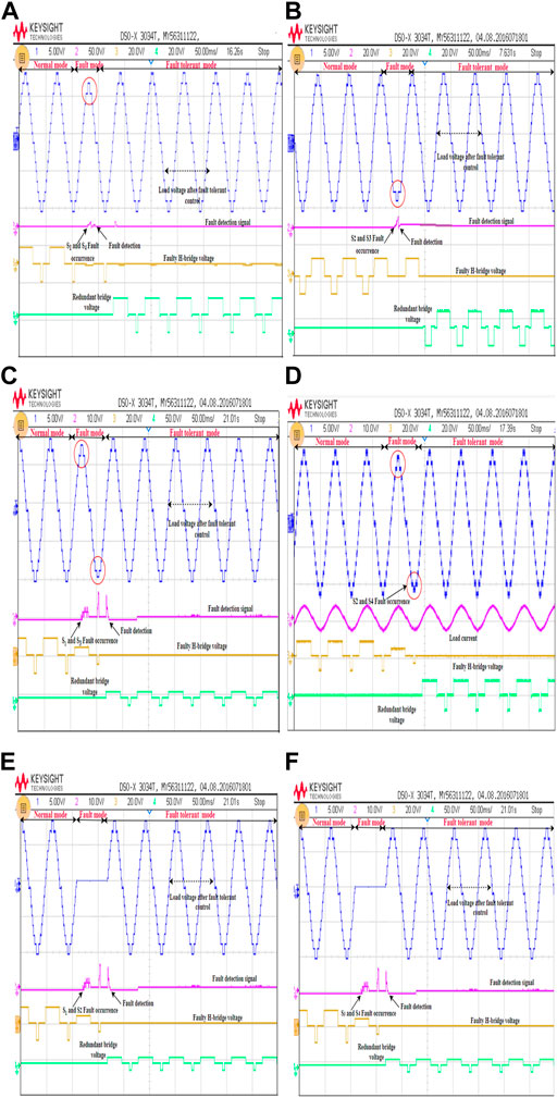
FIGURE 15. HIL results of fifteen-level CHB MLI under normal, fault, and fault-tolerant mode of DS fault at (A) S11, S14, (B) S12, S13, (C) S11, S13, (D) S12, S14, (E) S11, S12, (F) S13, S14.
Waveforms under normal, fault, and fault-tolerant operation are shown in Figure 14A. The fault is initiated at 2 s during the normal operation in HIL testing. When OCF occurs at switch S11 or S14, the fifteen-level load voltage has been reduced by one level representing the fault mode. The fault-tolerant operation begins once the fault signal has been detected, which is indicated by the rising edge of the fault detection signal. During the FT mode, the faulty H-bridge unit gets disconnected from the main inverter, and a redundant unit gets added. Once the fault is cleared, the load voltage, and current have been recovered to their normal state to ensure stability. Likewise, the OCF occurs at S12 or S13, the fifteen-level load voltage has been reduced by one negative level. The fault detection signal gives rise to one where the fault-tolerant mode begins. The reduced voltage level gets compensated by R-HB unit voltage as depicted in Figure 14B. The load voltage and current follow the same as normal and FT modes.
The OCF occurs at diagonal switches S11 and S14 or S12 and S13 are shown in Figures 15A, B. When these faults occur, the voltage level gets reduced abruptly, which causes serious damage to the load connected to it. Similarly, when the OCF occurs at switches S11 and S13, or S12 and S14, the load voltage is distorted in both the positive and negative half cycles, resulting in uneven voltage in the output, as shown in Figures 15C, D. When the OCF occurs at switches S11 and S12, or S13 and S14, no voltage appears across the load throughout the fault period. The fault-tolerant operation of the leg fault is shown in Figures 15E, F. The fault-tolerant operation begins immediately once the fault detection signal raises to 1. It can observe from the results, the load voltage and current maintain the same as the pre-fault voltage level in FT mode.
Using a spectrum analyzer and monitoring harmonics with respect to the amplitude of the fundamental signal, the harmonic distortion of the output voltage is measured. Figure 16 depicts the harmonic spectrum of the output voltage. Thus, it can be seen that the maximum double switch fault in a single bridge can be tolerated without any voltage level reduction or magnitude reduction. The feasibility of the proposed control has been further validated by the HIL findings displayed in Figures 14, 15 are in satisfactory correlation with the simulated results shown in Figures 10, 11.
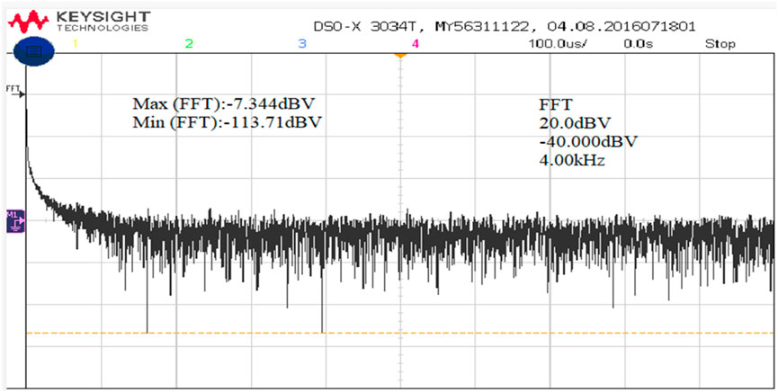
FIGURE 16. Harmonic spectrum of the output voltage of fifteen-level CHB MLI.
This section outlines the various parameters used to assess the competence of the proposed method. The performance of the proposed NN is assessed by the errors on the validation and test dataset using R and MSE. MSE, correlation coefficient R, and confusion matrix are the metrics used to evaluate the fault detection and classification problem. The correlation coefficient R indicates the accuracy of the trained NN that relates the target to the outputs. The perfect training shows that the R-value is close to 1, and the y-intercept is zero.
Figure 17 shows that the correlation coefficient equals 1, which means the proposed MLP-NN gives satisfactory training results. The MSE curve shows that testing and validation have the same values which gives the efficient training of the NN. The best validation performance at 1.2507e-24 at epoch 12, as shown in Figure 18. The confusion matrix identifies the fault classification accuracy of the proposed system. It gives the percentage accuracy about the correct and wrong classified fault data as shown in Figure 19. The row represents the output/true classes, the column represents the target/predicted classes, and the marginal cell shows the percentage errors between the output and target classes. The diagonal green cell indicates the correctly classified output and target classes while the cells above and below show the incorrectly classified data.
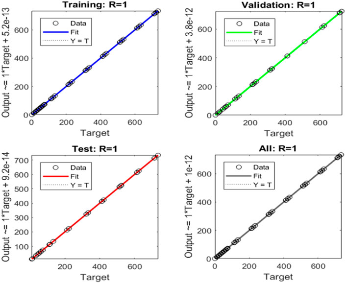
FIGURE 17. Linear regression curve
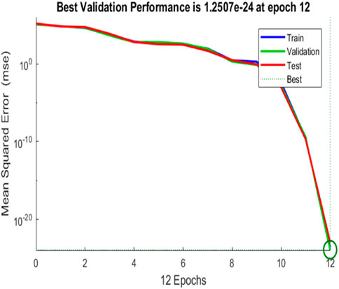
FIGURE 18. Mean squared error.
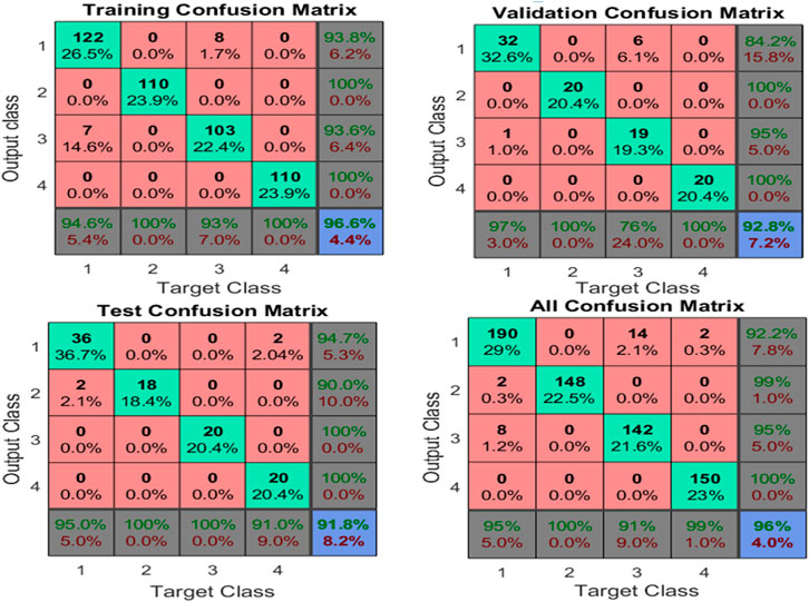
FIGURE 19. Confusion matrix for fault classification.
True positive rate (TPR) and false negative rate (FNR) are shown in the last column, which shows the percentage of data properly classified as belonging to a true class and the percentage of data incorrectly classified as belonging to another class. The bottom row shows the positive predictive value (PPV) and false detection rate (FDR), the proportion of data properly classified for a given true value, and the percentage of data that are wrongly categorized for a given true value, respectively. The observation shows that the average classification accuracy is around 96%, and very few data are incorrectly categorized into other classes.
Exemplary fault detection and tolerant approach must have the following characteristics: reliability, ideal fault detection time, single and multiple switch fault-tolerant ability, sustained output voltage during fault and post-fault operation, flexibility, and minimal computational effort. The FD approach presented in (Cheng et al., 2020b), (Anand et al., 2020) cannot locate the DS fault and requires more than one cycle to identify the OCF. To locate and classify the faulty switch pair and h-bridge, the mean value-based fault detection is presented in the literature (Raj et al., 2018b), which requires almost 40 ms to detect the faulty switch. However, the accuracy of FD for all the switch pairs is not discussed. The fault diagnostic procedures described in the literature rely on (Hu et al., 2020), (Parimalasundar and Suthanthira Vanitha, 2015) heuristic algorithms to determine the locations of faults and require a lot of training, testing data, and time to get properly trained. The architecture proposed in (Choupan et al., 2018) exploits the two bidirectional switches to tolerate the SS failure in the MLI. It takes about 60 ms to tolerate the SS fault and fails to tolerate the double switch fault. The topology presented in (Madhukar Rao. and Sivakumar, 2015) requires a bulky transformer and bidirectional switches to tolerate the SS fault. However, the topology delivers only the reduced output voltage even under post-fault conditions. The structure presented in (Mhiesan et al., 2020) utilizes the additional cross-coupled CHB unit to tolerate the single and multiple switch faults. Even with the inclusion of components, the topologies discussed in the literature cannot maintain the output voltage and current after a failure. Therefore, only with the addition of a single redundant HB unit, the suggested topology can provide the full rated output power in the case of a failure without increasing the size of the remaining healthy switches. In addition, it is obvious from the analysis that the presented topology employs the same number of switches in both normal and fault-tolerant operating modes. One of the primary benefits of the suggested topology is the removal of bidirectional switches, which were commonly employed in previously discussed topologies.
A comparison chart for the FD and FT MLI with other recently reported literature has been developed in Table 3 using the enlisted comparison. The proposed ANN-based fault detection and tolerant control are superior in terms of reduced computational complexity, fault detection time, component count, and increased reliability. Comparatively, the fault detection and tolerant time are less than the value given in (Mehta and PavanSahoo, 2020)-[29]. Furthermore, the proposed method has a 100% detection rate among switch no-fault and fault conditions and a classification accuracy of 96% between distinct SS and DS OCFs. The benefits of the proposed FTC structure include reduced harmonics, the absence of bidirectional switches, and the ability to handle multiple OCFs. Therefore, the presented fault-tolerant MLI is ideal for applications with high-reliability requirements. Renewable energy installations in remote and rural locations may benefit from this technology since repairs and maintenance may be time-consuming or expensive.
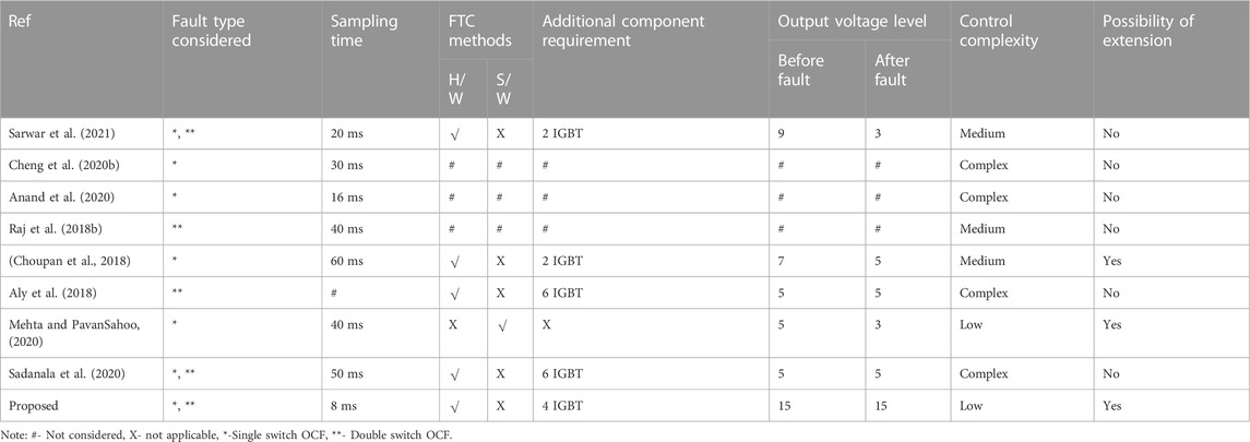
TABLE 3. Comparison of the proposed method with recent literature.
This article verifies the fault detection and tolerance of single-phase CHB inverters for various OCF conditions. The proposed approach evaluates the various single and multiple switch faults in different combinations. Based on the analysis, the MLP- ANN model has been created to test the viability of the proposed system under various OCF circumstances. The trained neural network accurately detects the faulty h-bridge and switch pairs within 8 ms and 16 ms for all the SS and DS faults with 96% classification accuracy. Also, developed the necessary fault tolerant control approach using the redundant h-bridge unit to provide the complete solution to OCFs. The fault-tolerant operation of single and multiple switches takes only about 20 ms (one fundamental cycle) to clear the fault. The main feature of the proposed system is maintaining the pre-fault voltage level during both the single-switch and multiple-switch fault conditions. Also, the voltage THD of output voltage has been maintained at the same level as 8.24% before and after fault conditions. The simulation and HIL results elucidate that the proposed topology was strong enough to tolerate OCF in single and multiple switches with preserved output voltage levels. The proposed fault diagnosis method can easily be generalized and applied to any number of voltage levels. In the future, a more advanced fault-tolerant control approach incorporating AI might more accurately detect the fault location with a better interpretation achieved by experimental hardware verification. Another approach is to incorporate various other faults and the impact of load fluctuations on the performance of the proposed system.
The raw data supporting the conclusions of this article will be made available by the authors, without undue reservation.
AS did the conception, and methodology, and performed the analysis. AS, NK, SK, and PV contributed to the review of the manuscript and presented suggestions and corrections. NK, PV, and MA supervised this work. MA, MB, MP, and SK arranged the funding acquisition. All authors contributed to the manuscript, read and approved the submitted version.
The authors declare that the research was conducted in the absence of any commercial or financial relationships that could be construed as a potential conflict of interest.
All claims expressed in this article are solely those of the authors and do not necessarily represent those of their affiliated organizations, or those of the publisher, the editors and the reviewers. Any product that may be evaluated in this article, or claim that may be made by its manufacturer, is not guaranteed or endorsed by the publisher.
Ali, M., Din, Z., Solomin, E., Cheema, K. M., Milyani, A. H., and Che, Z. (2021). Open switch fault diagnosis of cascade H-bridge multi-level inverter in distributed power generators by machine learning algorithms. Energy Rep. 7, 8929–8942. doi:10.1016/j.egyr.2021.11.058
Aly, M., Ahmed, E. M., and Shoyama, M. (2018). A new single-phase five-level inverter topology for single and multiple switches fault tolerance. IEEE Trans. Power Electron. 33 (11), 9198–9208. doi:10.1109/TPEL.2018.2792146
Anand, A., Akhil Vinayak, B., Raj, N., Jagadanand, G., and George, S. (2020). A generalized switch fault diagnosis for cascaded h-bridge multilevel inverters using mean voltage prediction. IEEE Trans. Ind. Appl. 56 (2), 1563–1574. doi:10.1109/TIA.2019.2959540
Asif, M., Tariq, Mohd, Sarwar, Adil, Hussan, M. R., Ahmad, S., Mihet-Popa, L., et al. (2021). A robust multilevel inverter topology for operation under fault conditions. Electronics 10 (24), 3099. doi:10.3390/electronics10243099
Cheng, S., Zhao, J., Chen, C., Li, K., Wu, X., Yu, T., et al. (2020). An open-circuit fault-diagnosis method for inverters based on phase current. Transp. Saf. Environ. 2, 148–160. doi:10.1093/tse/tdaa008
Cheng, S., Zhao, J., Chen, C., Li, K., Wu, X., Yu, T., et al. (2020). An open-circuit fault-diagnosis method for inverters based on phase current. Transp. Saf. Environ. 2 (2), 148–160. doi:10.1093/tse/tdaa008
Choudhury, S., Bajaj, M., Dash, T., Kamel, S., and Jurado, F. (2021). Multilevel inverter: A survey on classical and advanced topologies, control schemes, applications to power system and future prospects. Energies 14, 5773. doi:10.3390/en14185773
Choupan, R., Golshannavaz, S., Nazarpour, D., and Barmala, M. (2018). A new structure for multilevel inverters with fault-tolerant capability against open circuit faults. Electr. Power Syst. Res. 168, 105–116. doi:10.1016/j.epsr.2018.11.013
Gireesh Kumar, D., Ganesh, A., Venkata Sireesha, N., Singh Kshatri, S., Mishra, S., Sharma, N. K., et al. (2022). Performance analysis of an optimized asymmetric multilevel inverter on grid connected SPV system. Energies 15 (20), 7665. doi:10.3390/en15207665
Hu, H., Feng, F., and Wang, T. (2020). Open-circuit fault diagnosis of NPC inverter IGBT based on independent component analysis and neural network. Energy Rep. 6, 134–143. doi:10.1016/j.egyr.2020.11.273
Kim, S. M., Lee, J. S., and Lee, K. B. (2016). A modified level-shifted PWM strategy for Fault-Tolerant cascaded multilevel inverters with improved power distribution. IEEE Trans. Ind. Electron. 63 (11), 7264–7274. doi:10.1109/TIE.2016.2547917
Kumar, G. K., Parimalasundar, E., Elangovan, D., Sanjeevikumar, P., Lannuzzo, F., and Holm-Nielsen, J. B. (2020). Fault investigation in cascaded H-bridge multilevel inverter through fast Fourier transform and artificial neural network approach. Energies 13 (6), 1299. doi:10.3390/en13061299
Kuraku, N. V. P., He, Y., Shi, T., Gatla, R. K., and Yi, R. (2019). Fuzzy logic based open-circuit fault diagnosis in IGBT for CMLI fed PMSM drive. Microelectron. Reliab. 100–101, 113415. doi:10.1016/j.microrel.2019.113415
Madhukar Rao., A., and Sivakumar, K. (2015). A Fault-Tolerant single-phase five-level inverter for grid-independent PV systems. IEEE Trans. Ind. Electron. 62 (12), 7569–7577. doi:10.1109/TIE.2015.2455523
Maher, G., Hussain, S. M. S., Ustun, T. S., Sarker, M. R., Hannan, M. A., Mohamed, R., et al. (2021). Artificial neural networks based optimization techniques: A review. Electron 10, 2689–2721. doi:10.3390/electronics10212689
Mehta, M. K., Pavan, , , and Sahoo, S. (2020). A fault-diagnosis and tolerant control technique for five-level cascaded H-bridge inverters. Jaipur: IET Circuits, Devices & Systems, 366–376. doi:10.1049/cds2.12033
Mehta, P., Kumar, M., and Sahoo, S. (2018). Fault Diagnosis in five-level CHB inverter using normalization factor and THD analysis. India Int. Conf. Power Electron. IICPE 1, 1–5. doi:10.1109/IICPE.2018.8709547, no.
Mhiesan, H., Wei, Y., Siwakoti, Y. P., and Mantooth, H. A. (2020). A Fault-Tolerant hybrid cascaded H-bridge multilevel inverter. IEEE Trans. Power Electron. 35 (12), 12702–12715. doi:10.1109/TPEL.2020.2996097
Ouni, S., Narimani, M., Zargari, N. R., and Cheng, Z. (2019). A new Fault-Tolerant control method for cascaded H-bridge multilevel inverter to increase maximum output voltage. IEEE Energy Convers. Congr. Expo. ECCE, 2922–2927. doi:10.1109/ECCE.2019.8912282
Parimalasundar, E., and Suthanthira Vanitha, N. (2015). Identification of open-switch and short-switch failure of multilevel inverters through DWT and ANN approach using LabVIEW. J. Electr. Eng. Technol. 10 (6), 2277–2287. doi:10.5370/JEET.2015.10.6.2277
Raj, N., Jagadanand, G., and George, S. (2018). Fault detection and diagnosis in asymmetric multilevel inverter using artificial neural network. Int. J. Electron. 105 (4), 559–571. doi:10.1080/00207217.2017.1378382
Raj, N., Kale, T., Anand, A., Jagadanand, G., and George, S. (2018). Switch fault detection and diagnosis in space vector modulated cascaded H-bridge multilevel inverter. Int. J. Electron. 105 (12), 1977–1992. doi:10.1080/00207217.2018.1494327
Sadanala, C., Pattnaik, S., and Singh, V. P. (2020). Fault tolerant architecture of an efficient five-level multilevel inverter with overload capability characteristics. IET Power Electron 13 (2), 368–376. doi:10.1049/iet-pel.2019.0736
Sarwar, M. I., Sarwar, A., Farooqui, S. A., Tariq, M., Fahad, M., Beig, A. R., et al. (2021). A hybrid nearest level combined with PWM control strategy: Analysis and implementation on cascaded H-bridge multilevel inverter and its fault tolerant topology. IEEE Access 9, 44266–44282. doi:10.1109/ACCESS.2021.3058136
Sharma, V. K., Rinsha, V., and Jagadanand, G. (2021). Artificial neural network based open-transistor fault detection in symmetric cascaded H-bridge multilevel inverter. 2nd Int. Conf. Emerg. Technol. INCET, 2–7. doi:10.1109/INCET51464.2021.9456182
Siddique, M. D., Mekhilef, S., Shah, N. M., Sarwar, A., Iqbal, A., and Memon, M. A. (2019). A new multilevel inverter topology with reduce switch count. IEEE Access 7, 58584–58594. doi:10.1109/ACCESS.2019.2914430
Siva Priya, A., and Kalaiarasi, N. (2022). An extensive review on fault detection and Fault-tolerant control of multilevel inverter with applications. Int. J. Renew. Energy Res. 12 (2), 768–798. doi:10.20508/ijrer.v12i2.12586.g8465
Keywords: artificial intelligence, cascaded H-bridge multilevel inverter, fault diagnosis, fault-tolerant approach, total harmonic distortion
Citation: Sivapriya A, Kalaiarasi N, Vishnuram P, Abou Houran M, Bajaj M, Pushkarna M and Kamel S (2023) Real-time hardware-in-loop based open circuit fault diagnosis and fault tolerant control approach for cascaded multilevel inverter using artificial neural network. Front. Energy Res. 10:1083662. doi: 10.3389/fenrg.2022.1083662
Received: 29 October 2022; Accepted: 14 December 2022;
Published: 04 January 2023.
Edited by:
Thomas Alan Adams, Norwegian University of Science and Technology, NorwayReviewed by:
Bing Xiao, Northwestern Polytechnical University, ChinaCopyright © 2023 Sivapriya, Kalaiarasi, Vishnuram, Abou Houran, Bajaj, Pushkarna and Kamel. This is an open-access article distributed under the terms of the Creative Commons Attribution License (CC BY). The use, distribution or reproduction in other forums is permitted, provided the original author(s) and the copyright owner(s) are credited and that the original publication in this journal is cited, in accordance with accepted academic practice. No use, distribution or reproduction is permitted which does not comply with these terms.
*Correspondence: Mohamad Abou Houran, aG91cmFuQHhqdHUuZWR1LmNu; Salah Kamel, c2thbWVsQGFzd3UuZWR1LmVn
Disclaimer: All claims expressed in this article are solely those of the authors and do not necessarily represent those of their affiliated organizations, or those of the publisher, the editors and the reviewers. Any product that may be evaluated in this article or claim that may be made by its manufacturer is not guaranteed or endorsed by the publisher.
Research integrity at Frontiers
Learn more about the work of our research integrity team to safeguard the quality of each article we publish.