 Zhenshun Liu
 Sheng Zhang2†
- 1State Key Laboratory of Nuclear Power Safety Monitoring Tech and Equip, Shenzhen, Guangdong, China
- 2Tsinghua University Shenzhen International Graduate School, Shenzhen, Guangdong, China
- 3China Nuclear Power Engineering Co., Ltd, Shenzhen, Guangdong, China
The predicted leakage rate of piping circumferential through-wall cracks (CTWC) under various loading levels is a critical factor for the application of leak-before-break (LBB) technology. In current engineering approaches, the effect of welding residual stress has not been carefully taken into account. In this paper, both numerical analyses and comparative verification are adopted to examine the influence of typical welding residual stress field on the crack opening displacement for austenitic stainless steel piping with representative geometric dimensions and in situ measured material performance curves. An in-depth investigation is carried out to reveal the effect of the residual stress on morphological parameters of the CTWC flow channel. In the case where the residual internal stress of welding has the greatest effect, the Henry-Fauske model is employed to analyze the flow medium passing through the CTWC and the corresponding leak rate for a typical nuclear power plant. The results indicate that the welding residual stress leads to a substantial change in the crack opening displacement and crack morphology parameters. Both the current GE/EPRI method and the NUREG/CR-6837 modification recommended by the American Electric Power Research Institute underestimate the effect of this phenomenon, resulting in a higher prediction of the medium leakage rate. A similar situation is most likely to occur for the cases of short cracks in thin-walled piping and long cracks in thick-walled piping. Additionally, the obtained results reveal that the welding residual stress causes the whole crack surface to open negatively, and the axial line of the long crack on the thick-walled piping is close to a conic curve under specific conditions.
1 Introduction
A double-ended guillotine break (DEGB) of high-energy piping in a nuclear power plant represents an accident on the basis of hypothetical design. Under the premise of applying the leak-before-break (LBB) technology, the dynamic loads caused by the double-end fracture of the pipeline could be canceled off, and the design scheme could also be optimized, both of which helps to enhance the economy and safety of the power plant (Wichman and Lee, 1990; U.S.N.R.C. NUREG -1061, 1984).
The basic principle of the LBB technology for nuclear piping refers to three aspects: 1) Leakage occurs after the emergence of a circumferential through-wall crack (CTWC). 2)Medium leakage could be monitored online in time. 3) The crack remains stable during the period from crack emergence to locating leakage, which does not lead to DEGB of the piping (Wichman and Lee, 1990; U.S.N.R.C. NUREG -1061, 1984). Commonly, a stable flow channel is formed under the loading action, after which the medium is leaked to the outer wall of the pipe through the flow channel. The leakage rate is a key factor that has a crucial influence on the application of the LBB technology. In a general LBB analysis approach, the geometric dimensions of the pipe and crack, the morphology of the flow channel, the state of the medium, and the fracture mechanics parameters under the joint action of internal and external loads have vital influences on the predicted leakage rate of the medium.
In the current LBB technology system, GE/EPRI or LBB/ENG model is generally employed to predict the stability and crack opening displacement (COD) of CTWC, and then Henry-Fauske uniform unbalanced two-phase flow model or Moody model is applied to analyze the leakage rate (Moody, 1965; Rahman et al., 1998a). However, the influence of the welding residual stress (WRS) is neglected in these models.
In previous research works, the vital influence of WRS on the through-wall crack was not included, and the studies were only restricted to piping surface cracking (Rahman et al., 1997; Coules and Smith, 2015; Namburu et al., 2018; Mirzaee-Sisan and Wu, 2019; Mångård and Hannes, 2020). Generally, it is believed that the WRS mainly affects surface cracks rather than through-wall ones (Ghadiali et al., 1996; Rahman et al., 1997; Webster et al., 2014; Coules and Smith, 2015; Namburu et al., 2018; Mirzaee-Sisan and Wu, 2019; Mångård and Hannes, 2020). Recent studies have revealed that the effects of WRS on CTWC cannot be ignored (Rahman et al., 1998b; Shim et al., 2009; Macurova et al., 2010; Huang et al., 2020; Huang and Zhou, 2020). In the LBB technology system, no direct results have been derived regarding the effects of WRS on the medium leakage rate of CTWC in the piping. On the other hand, the indirect research works focus on the following four aspects: distribution of WRS in piping, loading mode of the WRS in numerical analysis, the influence of the WRS on COD of CTWC in piping, and the relationship between COD and the crack morphology parameters of CTWC. In the following, these items are explained one-by-one in details.
(i) Numerical simulation and experimental measurement are employed to examine the distribution of WRS in piping, but the limitation of measurement and complexity of WRS are still difficult to resolve. There are three main types of research on the distribution of WRS: (a) simplified envelope values of WRS are developed for engineering analysis with references to many typical welding processes (EPRI, 1986; Wallin and Nevasmaa, 1997; Rahman et al., 1998b; Standard, 2015; Mirzaee-Sisan and Wu, 2019); (b) simplified probability distribution model of WRS has been established with consideration of uncertain conditions (Itoh et al., 2008; Katsuyama et al., 2010; Brust et al., 2011; Benson et al., 2014); (c) detailed analyses and measurements of WRS for specific scenarios and particular processes have been proposed (EPRI, 1986; Rahman et al., 1998b; Macurova et al., 2010; Mccluskey et al., 2011; Miessi et al., 2011; Wei et al., 2011; Yang et al., 2011; Lukes, 2013; Song and Dong, 2015; Dehaghi et al., 2017). Especially, the literature (EPRI, 1986) (from The Task Group on Piping Flaw Evaluation of ASME section XI, or TGPFE) provides a simplified WRS recommendation (EPRI, 1986; Rahman et al., 1998b) for the typical welding process of stainless steel piping in terms of extensive experiments and numerical simulations of envelope results. The simplified WRS recommendation from TGPFE is broadly employed in nuclear power engineering.
(ii) For the WRS loading during a numerical analysis of CTWC, the current method is to load WRS from non-cracked pipe structures onto the inner surface of through-wall cracks using the crack surface pressure approach (Rahman et al., 1998b; Kiciak et al., 2003; Scott R, 2005; Anderson and Glinka, 2006; Zang et al., 2009; Fan et al., 2015), while neglecting the release of residual strain and the redistribution of stress during the process of the CTWC formation. Zang et al. (Zang et al., 2009) have showed that the prediction and analysis results of COD by crack surface pressure methodology are relatively reasonable when the crack size is small.
(iii) In the LBB technology system, no suitable engineering analysis method has been established to properly consider the impact of WRS on the COD values of CTWC. For COD predictions of CTWC in piping, the linear elastic model, the elastic model with small ranges of local plasticity modification, and the elastoplastic model have been successively constructed, and simplified empirical formulas have been summarized (Irwin, 1960; Lyellsanders, 1982; Paris and Tada, 1983; Klecker et al., 1986; Kumar and German, 1988; Bhandari et al., 1992; France et al., 1997; Takahashi, 2002; Kiciak et al., 2003; Bourga et al., 2015). Nevertheless, stresses that are not uniformly linear along the radial direction of the pipe such as WRS could not be introduced to these empirical formulas. On contrary, uniformly linear stresses resulting from the axial force and bending moments of the pipe can be utilized in these equations. For instance, WRS could not be solved in the elastoplastic COD analysis formula developed by General Electric (GE)/EPRI (Kumar and German, 1988) and Battell (Young et al., 2012), which however has been extensively exploited in the LBB technology system. Some recent studies (Kiciak et al., 2003; Anderson and Glinka, 2006; Lewis and Wang, 2008; Fan et al., 2015; Huang et al., 2020) have evaluated the COD values of CTWC by the parameterized finite element analysis and by constructing weight functions which can account for the impact of WRS loads. Nevertheless, the weight function approach is only validated online in the field of elastic fracture mechanics.
On the other hand, the main findings of the WRS effects on COD of CTWCs are summarized herein. In 1998, Rahman et al. (Rahman et al., 1998b) investigated the influence of WRS on COD of CTWC in TP304 stainless steel pipes through simplified linear elastic 3D finite element models. The achieved results indicated that WRS could cause crack surface rotation, and the leakage of the internal medium is lessened to a certain extent. Therefore, CTWC may remain closed under the action of lower external loads. In traditional GE/EPRI models, the COD prediction value of CTWC increases linearly from zero with the growth of an exerted load, but it overestimated the medium leakage in the LBB technology to the detriment of safe and reliable leak monitoring. These technical findings were also confirmed by NRC (Scott et al., 2002; Scott R, 2005) and Kiciak et al. (Kiciak et al., 2003) Through the Battelle integration of nuclear piping (BINP) program, the NRC exploited elastoplastic finite element analysis models to examine conditions on type 316 stainless steel pipes using the typical welding process. They introduced a specific factor into the conventional GE/EPRI formula to compensate for the WRS-induced crack closure effect and COD on the outer points of the crack surface under zero externally applied loads (Scott R, 2005). However, the applicability of this correction factor to the simplified WRS, which was recommended by TGPFE, has not been verified yet. Furthermore, the law of the WRS’s impact on COD after crack opened has not been concluded.
(iv) In the study on the relationship between COD of CTWC and the crack channel morphology parameters, Rahman et al. (Rahman et al., 1995) gave the functions of calculating crack channel parameters on the basis of COD. These functions allowed the flow path morphological parameters of some specific engineering objects to be analyzed.
To be concise, the effects of WRS on the leakage rate through CTWC in stainless steel piping in the LBB technology cannot be ignored, but no direct results have been unveiled. Therefore, in the present study, the simplified WRS recommendation from TGPFE, the crack surface pressure method to load WRS onto a numerical analysis model, and the elastoplastic numerical analysis model are all adopted to examine the influence of WRS on COD of CTWC in various conditions, and their results are compared. Subsequently, the effect of WRS on the CTWC channel morphology parameters is explored by the relationship between COD and the crack channel parameters according to Rahman et al. (Rahman et al., 1995; Bourna, 2017). Further, the effect of WRS on the leakage rate is investigated by the Henry-Fauske model (Abdollahian and Chexal, 1983).
2 Finite element analysis (FEA) of COD
2.1 WRS in stainless steel pipe welds
The WRS is closely related to the pipe size, welding condition, and welding process. For thin-walled pipes, the stress field of the inner wall towards the outer wall changes from tensile to compression. For thick-walled pipes, the stress fields from the inner to the outer walls are sequentially tensile, compression, and tensile (EPRI, 1986; Rahman et al., 1998b).
With the experimentally observed data and the FEA results, TGPFE recommends the axial WRS distribution values for thin-walled pipes (t < 25.4 mm) and thick-walled pipes (t ≥ 25.4 mm), as shown in Table 1 (EPRI, 1986). For thick-walled pipes without measurement data, the inner WRS is conservatively assumed to have reached the yield stress (Sy).
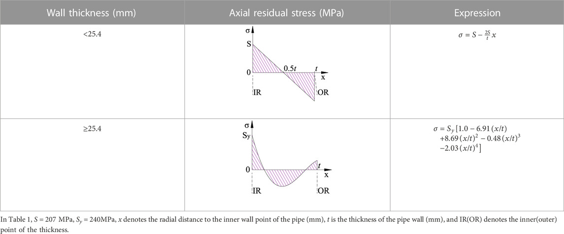
TABLE 1. The WRS recommended by the TGPFE (EPRI, 1986).
2.2 FEA input parameters
In the present study, the typical WRS recommended in Table 1 is suitable for TP304 stainless steel and its welding material 316L that are used to examine the influence of WRS on COD and flow channel parameters of CTWC. These results are of interest under the conditions of the circumferential half-crack angle of 0.0625π, 0.125π, 0.25π, and 0.45π, the wall thickness of 7.5, 15, 22.5, 30, and 40 mm, radius/wall thickness ratio (Ro/t) of 5, 10, and 20, and stress-strain curves of various materials. The most critical parameters are selected to analyze the variation of the medium leakage rate of saturated steam in the piping. The material properties have been demonstrated in Table 2, and the input parameters of the analysis model are provided in Table 3.
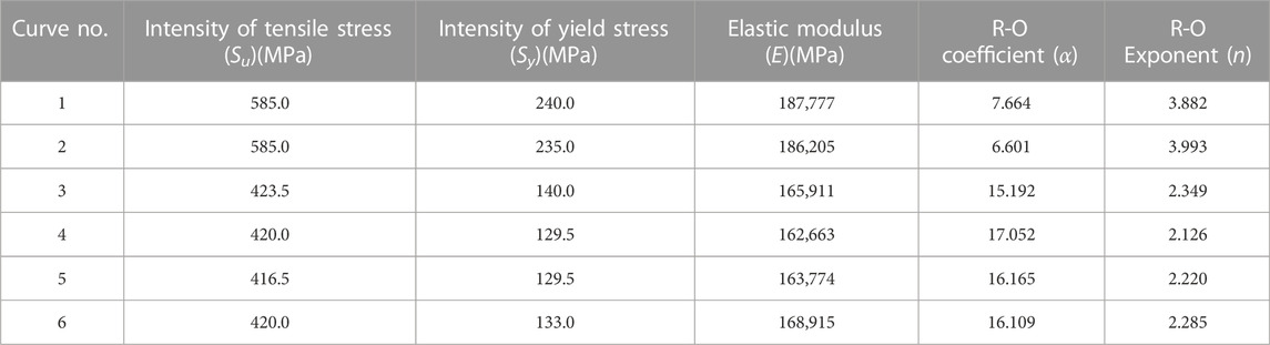
TABLE 2. Material properties.

TABLE 3. Input parameters of the finite element analysis model.
2.3 FEA modelling
The parametric analysis is performed in ABAQUS (Systemes, 2014) according to the input parameters given in Table 3. The numerical analysis model represents a three-dimensional solid symmetry model with a CTWC, and its element type is C3D20R. A total of 17,490 cells are divided into 10 grids from the innermost surface to the outermost surface of the pipe, regardless of the wall thickness. In order to avoid the effect of the end constraint, the length of the pipe model is set equal to 5 times of the radius of the pipe.
The constitutive relation of the stainless steel adopts the Ramberg-Osgood equation with the Poisson’s ratio of 0.3. During the structural analysis of the pipe elements, some of the meshes around the crack tips enter the plastic phase while the remaining meshes stay in the elastic phase. At the cross-section associated with the crack location, the crack surface is traction free, while at other cross-sections the axial displacements are constrained, as illustrated in Figure 1.
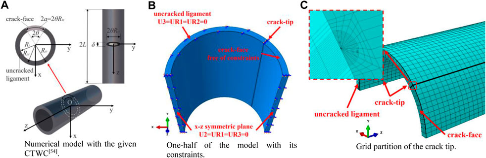
FIGURE 1. Numerical model. (A) Size parameters in numerical model. (B) One-half of the model with its constraints. (C) Grid partition of the crack tip.
Under the action of an externally exerted load and WRS, both the positive displacement and the negative displacement can be produced at the crack surface. The positive displacement triggers crack opening while the negative displacement can force the crack to close. The two crack surfaces are in contact with each other as the crack surface displacement is negative.
Herein, the deformation of two crack surfaces after contact is not considered because once it occurs, the crack is regarded closed. This means that the leakage rate of the medium vanishes. However, there is no reference for exploring the post-contact leakage issue.
The Cartesian coordinate system is employed to establish the model such that the right-hand rule is satisfied. The pipe axis is denoted by the Z-axis, the crack surface is located on the plane of Z = 0, and the center of the circle obtained from the plane Z = 0 segment of the pipe, is located at the original point (0,0,0), and the symmetric axis of the circle (including the crack surface) is represented by the X-axis. U1, U2, and U3 represent the degrees of freedom (DOFs) of translation motion in the X, Y, and Z directions, while UR1, UR2, and UR3 represent the DOFs of rotation fields around the X, Y, and Z axes, respectively. In Fig. 1(b), U3 = UR1 = UR2 = 0 indicates that the DOFs pertinent to the translational motion in the Z-direction (axial), as well as rotations about the X and Y axes, are fully constrained. Further, the boundary conditions U2 = UR1 = UR3 = 0 indicate that the translational motion in the Y-direction, as well as rotations about the X and Z axes, of these DOFs, are set zeros.
2.4 loading strategy
The loads on a pipeline include weight, internal pressure, thermal expansion, thermal stratification and earthquakes, etc (Zhong and Ban, 2022a; Zhong and Ban, 2022b; Zhong et al., 2022). These loads produce axial forces and bending moments along the pipeline. The external load in this paper stands for all these loads in an ideal style, i.e. the bending moment is used to represent the effect of external load because COD of CTWC is more sensitive to this moment (see (Rahman et al., 1998b)). When a moment is applied at the free end, it should be loaded around the X axis to obtain the maximum bending stress at the most outer point of CTWC. WRS is applied to the inner crack surface. The loading sequence is WRS first, and then the end bending moment of piping. The applied moment increases from zero until the crack destabilizes. The corresponding critical load associated with the instability of CTWC could be calculated by the GE/EPRI approach (Norris, 1987).
3 CTWC flow parameter analysis
In the Henry-Fauske model (Abdollahian and Chexal, 1983; Rahman et al., 1995; Gill et al., 2015), the parameters of the crack flow path through the wall include the crack opening area (COA), the area ratio of the exit to the entrance of the flow path, the surface roughness of the crack, and the number of crack channel corners. These factors can affect pressure loss during medium leakage. Rahman’s (Rahman et al., 1995) test results show that the following relations can be utilized to evaluate the surface roughness of the crack (K) and the number of channel corners (nt):
where
4 Evaluation of the medium leakage rate
For uniform and unbalanced two-phase flow, the Henry-Fauske model is employed for the medium leakage rate analysis (Abdollahian and Chexal, 1983; Gill et al., 2015). In the case of saturated vapor in the piping, the continuity equation of the fluid reads:
and the momentum equation is expressed by
The pressure loss-constraint equation can be obtained by integrating from both sides of Eq. 4 along the CTWC path in view of Eq. 3:
where G is the mass flux along the crack channel (kg/(m2. s)), A is the cross-section area of the crack channel (m2), Z is the axial coordinate of the crack flow channel (m), p is the inner pressure (Pa), D is the equivalent diameter of piping (m), ρ is the fluid density (kg/m3), f is the friction coefficient, Po is the inlet pressure (Pa), Pc is the outlet pressure (Pa), ΔPe is the inlet pressure loss (Pa), ΔPae is the acceleration pressure loss due to the phase transition (Pa), ΔPaa is the pressure loss caused by the area change (Pa), ΔPf is the pressure loss caused by friction (Pa), and ΔPtotal is the total pressure loss (Pa).
Assuming that an expansion process of vapor is an isoentropy process which follows the thermodynamic equilibrium of ideal gases, Eq. 6 (Abdollahian and Chexal, 1983; Gill et al., 2015) could be derived from Eqs. (3 & (5). It is the mass velocity equation of the medium at the outlet of the flow channel.
where Gc is the critical mass flux at the outlet (kg/(m2. s)), gc is a constant,x is the vapor content of the medium at the outlet cross-section, xE is the vapor content of the medium in the equilibrium state, κis the isoentropy expansion index, νl is the liquid-specific volume (m3/kg), νg is the steam specific volume (m3/kg), p is the isoentropy equilibrium atmospheric pressure (Pa), and N is the imbalance parameter.
According to Eqs 5, 6, the exit pressure (Pc) and the leakage mass flux (Gc) can be obtained, and the parameters required for evaluating the pressure drop component could be calculated according to the enthalpy flow assumption. Repeated iterations of Pc and Gc are required in the entire solution process until Eqs 5, 6 are satisfied. The leakage rate (Le) can be then computed according to the following relation:
where Ac is the outlet section area.
5 Results
5.1 Crack closure caused by WRS
Since WRS acts in both tensile and compressive forms on the crack surface, the crack could be closed if the tensile stress under external load is low. For instance, the outer wall can be closed easily for thin-walled pipes, as Figure 2A shows.
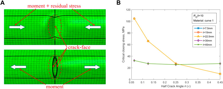
FIGURE 2. The crack closure induced by the moment and its combination with the WRS. (A) Schematic representation of the crack closure. (B) Plots of CCS in terms of crack angle for various crack angles.
In this paper, the crack is regarded totally open when the displacements of all the nodes on the middle line of the crack surface are positive in the direction of the crack opening. The maximum bending stress under the external loads is known as critical closing stress (CCS) once the crack reaches its opening state. The results of CCS under different input parameters are acquired and presented in Fig. 2(b). It is observed that the variation rate of CCS for the pipes with thickness t > 25.4 mm is obviously different from that of the pipes with t < 25.4 mm. Such a difference is due to various expressions of WRS for thin-walled and thick-walled pipes. The crack becomes closed once δWRS (COD produced by WRS) is equal to δM (COD produced by CCS). For thin-walled pipes, δWRS is not sensitive to varying θ because at a small θ value WRS has already triggered sufficient rotation of the crack surface. For thick-walled pipes, δWRS increases as θ increases, and only a large enough θ is able to make the crack surface deform under WRS. For both thin-walled and thick-walled pipes, CCS decreases significantly with the increase of θ under the condition δM = δWRS. Expressions in Table 1 are reliable to represent the general variation law of WRS in nuclear piping by TGPFE, and they exhibit a good envelope (see (EPRI, 1986)). In Section 5.2, the influence of WRS on COD is explored in details.
5.2 COD variation of CTWC caused by WRS
In this subsection, the analysis results with and without WRS are extracted from the three-dimensional finite element analysis model for comparative studies. The medium leakage rate is zero before the external loading starts to change the closed state of the crack. The DEGB occurs after an unstable crack is caused by the externally exerted load. These two situations are not of reference significance. Therefore, only the case that the external load stress is greater than the CCS and smaller than the critical instability stress is taken into account for CTWC.
For the case of RO/t = 10, the material performance parameters are selected from those of Curve one in Table 2. The effect of WRS on COD values located on the outer wall points of CTWC is examined according to the input parameters given in Table 3 for various wall thickness, crack angle, and external load conditions, as illustrated in Figures 3, 4.
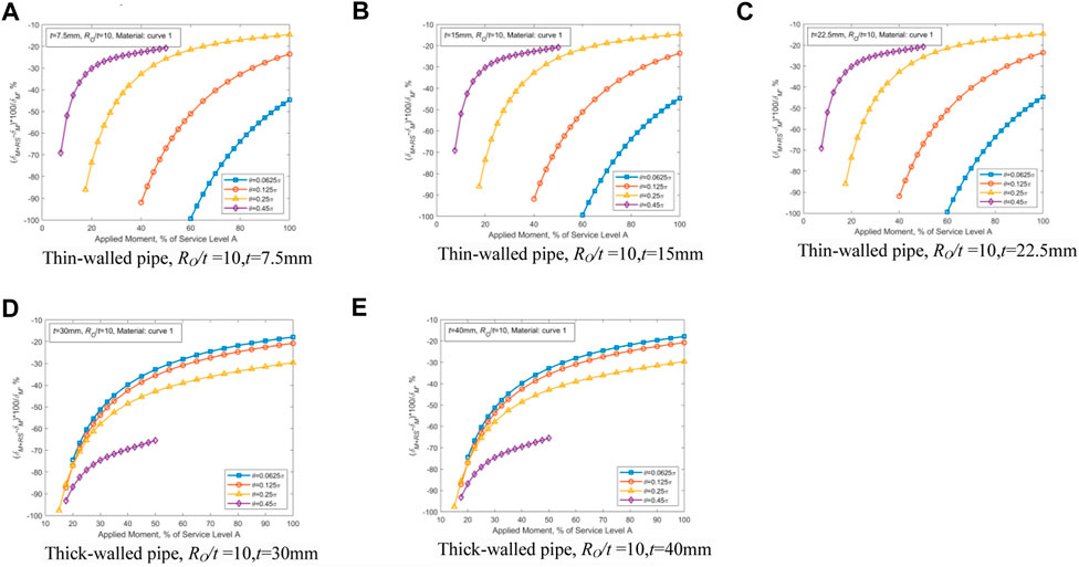
FIGURE 3. Effect of WRS on the external wall’s COD. (A) Ro/t = 10, t = 7.5 mm. (B) Ro/t = 10, t = 15 mm. (C) Ro/t = 10, t = 22.5 mm. (D) Ro/t = 10, t = 30 mm. (E) Ro/t = 10, t = 40 mm.
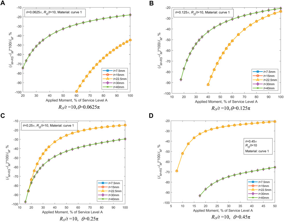
FIGURE 4. Effect of WRS on the external wall’s COD. (A) RO/t = 10, θ = 0.0625π. (B) RO/t = 10, θ = 0.125π. (C) RO/t = 10, θ = 0.25π. (D) RO/t = 10, θ = 0.45π.
As shown in Figure 3, for thin-walled piping, a smaller crack angle could lead to a higher impact of WRS on COD. For thick-walled piping, a larger crack angle would lead to greater influence of WRS on the COD.
As illustrated in Figure 4, the influence of the variation of the wall thickness t on COD is so small that it can be ignored. With the growth of the half crack angle (θ), the effect of WRS on COD of thin-walled pipes lessens, and such an effect for thick-walled pipes magnifies. For thin-walled pipes, WRS has the greatest effect in the case of θ = 0.0625π. For thick-walled pipes, WRS exhibits the highest effect in the case of θ = 0.45π. The WRS influence could be reasonably reflected by the ratio of COD caused by WRS to the external loading at the outer wall point of CTWC. As the crack angle θ increases, both the cross-sectional area of the piping and the bending stiffness decrease, thereby COD increases under the action of WRS and external loading. The TGPFE-based WRS provided in Table 1 for thin-walled pipes acts in the form of internal tension and external compression and causes the crack surface to rotate along the neutral axis. When θ is small, the applied WRS is able to make the crack surface rotate and then increase the external point COD. On the contrary, for thick-walled pipes with small θ, because of the tension-compression-tension joint action, the rotation of crack surface and associated COD cannot be formed. When θ is too small to reduce the constraint effect of the non-cracked cross section, the effect of WRS is not obvious on thick-walled pipes.
Based on the results displayed in Figures 3, 4 and the laws obtained above, the parameters with the greatest effect of WRS on COD are selected (i.e., t = 15 mm with θ = 0.0625π and t = 40 mm with θ = 0.45π, respectively, for thin-walled and thick-walled pipes) to further investigate the effect of RO/t, and the obtained results are demonstrated in Figures 5, 6.
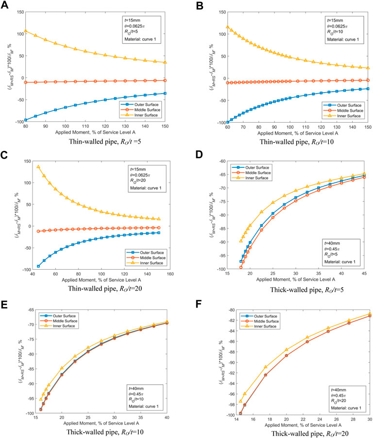
FIGURE 5. Effect of WRS on COD for RO/t = 5, 10, and 20 at different locations. (A) Thin-walled pipe, RO/t = 5. (B) Thin-walled pipe, RO/t = 10. (C) Thin-walled pipe, RO/t = 20. (D) Thick-walled pipe, RO/t = 5. (E) Thick-walled pipe, RO/t = 10. (F) Thick-walled pipe, RO/t = 20.
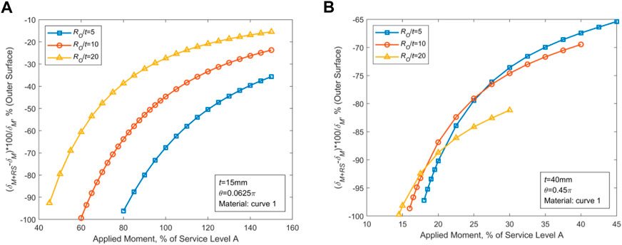
FIGURE 6. Effect of WRS on the outer wall’s COD. (A) Effect of WRS on thin-walled piping. (B) Effect of WRS on thick-walled piping.
Figures 5, 6 show that for thin-walled pipes, variation of the outer diameter has a substantial influence on COD under the action of WRS. However, little influence is observed in thick-walled pipes. For thin-walled pipes, WRS has a greater effect on smaller RO. For thick-walled pipes, the WRS’ effect increases with RO.
Judged by the above analysis, two sets of parameters are selected that maximize the effect of WRS on the CTWC-COD values: RO/t = 5, t = 15mm, θ = 0.0625π for thin-walled piping, and RO/t = 20, t = 40mm, θ = 0.45π for thick-walled piping, and the effects of material performance are further investigated using the material parameters in Table 2 (Curves 1–6), as demonstrated in Figures 7, 8. Figures 7, 8 imply that the effect of WRS on COD values is significantly altered by differences in material. In Table 2, WRS has the greatest effect on COD due to the material properties associated with Curve 1.
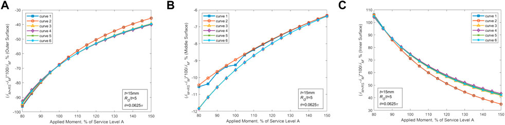
FIGURE 7. Effect of WRS on COD in various positions of the thin-walled piping with different material properties. (A) Changes in COD at the outer wall points (B) Changes in COD at the midpoints. (C) Changes in COD at the inner wall points.
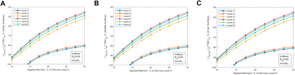
FIGURE 8. Effect of WRS on COD in various positions of the thick-walled piping with different material properties. (A) Changes in COD at the outer wall point (B) Changes in COD at the midpoints. (C) Changes in COD at the inner wall points.
5.3 Morphology parameters of the crack flow channel under WRS’ action
Aided by the analysis results in Morphology parameters of the crack flow channel under WRS’ action, two groups of parameters that can maximize the effect of WRS on COD value of CTWC are selected. According to the approach introduced in Morphology parameters of the crack flow channel under WRS’ action, the effects of WRS on the flow channel parameters (global roughness K, the number of 90° corners nt, COA, and the ratio of exit to import area rOI) of CTWC in thin-walled and thick-walled pipes are analyzed for the following cases: Ro/t = 5, t = 15 mm, θ = 0.0625π and RO/t = 20, t = 40mm, θ = 0.45π. The material properties are selected as the values corresponding to curve one in Table 2, and the results are illustrated in Figure 9.
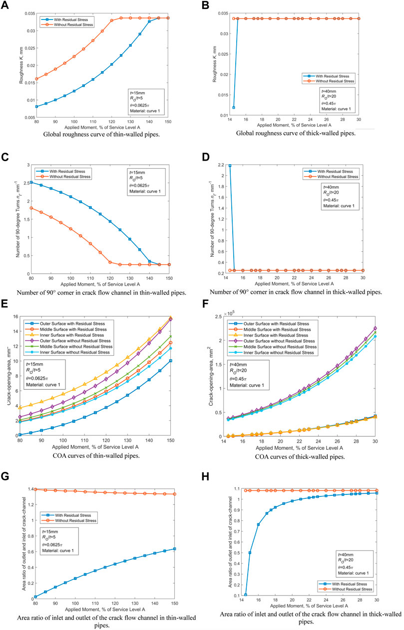
FIGURE 9. Morphology parameters of the crack flow channel under WRS′ action. (A) Global roughness curve of thin-walled pipes. (B) Global roughness curve of thick-walled pipes. (C) Number of 90° corner in crack flow channel in thin-walled pipes. (D) Number of 90° corner in crack flow channel in thick-walled pipes. (E) COA curves of thin-walled pipes. (F) COA curves of thick-walled pipes. (G) Area ratio of inlet and outlet of the crack flow channel in thin-walled pipes. (H) Area ratio of inlet and outlet of the crack flow channel in thick-walled pipes.
Figures 9A–D illustrate that the effect of WRS on K and nt is not significant. In Figures 9E–H, it is showed that in the presence of WRS, the COA value is reduced by at least 37% and 80% for thin-walled and thick-walled pipes, respectively. Similarly, rOI is reduced, especially for small diameters of thin-walled pipes (see Figure 19). For both thin-walled and thick-walled pipes, the effect of WRS on COA and ROI lessens with the growth of the external load.
5.4 Effect of WRS on medium leakage rate
The analysis results of Sections 5.1–5.3 entail the most obvious parameters affected by WRS to be selected for thin-walled and thick-walled pipes. The Henry-Fauske uniform unbalanced two-phase flow model (Abdollahian and Chexal, 1983) is employed to examine the variation of the medium leakage rate through the CTWC under various stress levels. The input parameters used are presented in Table 4.
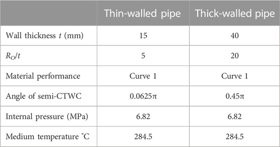
TABLE 4. Input parameters for the leakage rate analysis.
The analysis results of thin-walled and thick-walled pipes have been provided in Figure 10, respectively. By comparing the plotted results, it is obvious that WRS can reduce the leakage rate of medium significantly before the CTWC instability occurs. The leakage rates are reduced by at least 46.55% for thin-walled and by 14.46% for thick-walled pipes.
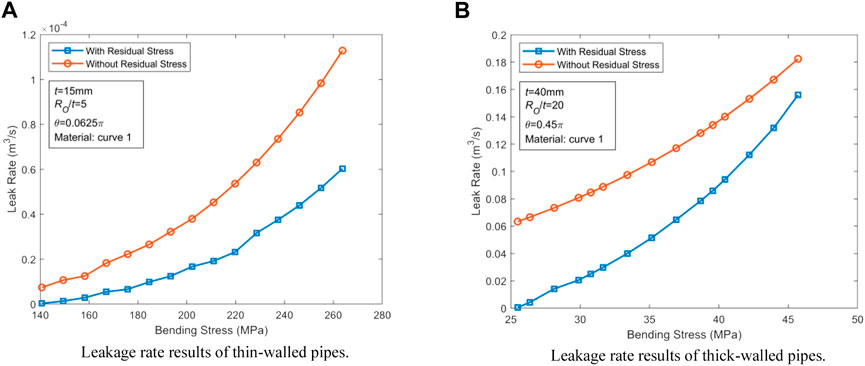
FIGURE 10. Effect of WRS on medium leakage rate. (A) Leakage rate results of thin-walled pipes. (B) Leakage rate results of thick-walled pipes.
6 Discussion
6.1 Action mode of WRS under different crack angles
The distribution of the axial WRS in Table 1 tells that under zero external load, WRS of the inner part of the thin-walled pipe is tensile while the outer part is compressive. As a result (Wichman and Lee, 1990), it has been shown that the CTWC inner wall points tend to open under zero externally applied loads, but the intercept of equations describing COD is not expected to be zero. In the presence of a large crack angle, WRS also results in a negative COD at the CTWC inner wall position of thin-walled pipes, as demonstrated in Figures 11, 12. The principles underlying this phenomenon are discussed in this subsection.
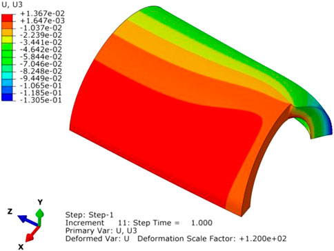
FIGURE 11. Deformation diagram at half crack angle of 0.45π.
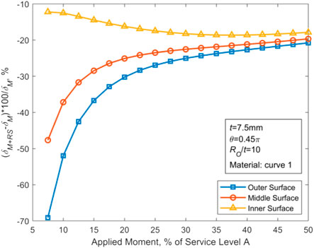
FIGURE 12. Negative COD at the CTWC inner wall position of thin-walled pipe.
In Figure 13, IP denotes the inner portion of the cracked surface, and OP represents the outer portion of the cracked surface.IP is subjected to tensile stress. Its corresponding area is represented by SIP. Op is subjected to the closure stress. Its area is denoted by SOP. The stress distributions of these two zones are consistent in form and opposite in direction. The ratio of the area of the inner and outer regions is given by:
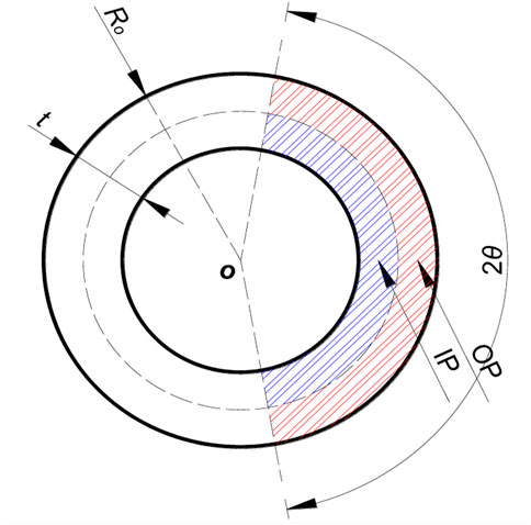
FIGURE 13. Inner ring region IP and outer ring region OP.
The corresponding variation curve in terms of Ro/t is plotted in Figure 14. It can be seen that as RO/t approaches infinity, the ratio in Eq. 8 tends to 1, and the resultant tension and resultant pressure caused by WRS on the thin-walled crack surface are equivalent. At this time, WRS increases COD on the inner wall and decreases COD on the outer wall. For the small values of RO/t, the difference between the inner and outer regions of CTWC becomes larger and larger. The increasing difference leads to the negative displacement of the whole crack surface (Figure 15) in that the resultant force on crack surface is increased along the closed direction.
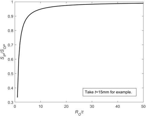
FIGURE 14. Variation curve of SIP/SOP as a function of RO/t.
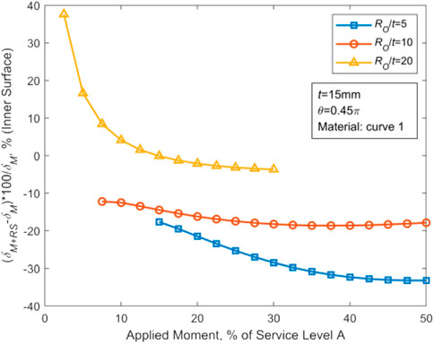
FIGURE 15. Variation of the inner wall ΔCOD with the stress level under different RO/t with t = 15 mm, θ = 0.45π, and material curve 1.
The discrepancy between the areas of the inner and outer ring regions can be written by:
For the case of constant values for RO and t, the associated variation curve as a function of θ can be obtained as demonstrated in Figure 16. The smaller the crack angle is, the closer SOP and SIP are. When the crack angle is larger, the discrepancy between SOP and SIP becomes larger. Finally, the difference between the tensile force and the pressure generated by WRS is larger and larger. In other words, the compressive stress dominates the movement of the center of the crack surface of CTWC in pipes, resulting in displacement along the crack closure direction. The corresponding plots for a typical case have been depicted in Figure 17. To sum up, for thin-walled pipes, when the crack angle is large or RO/t is small, WRS may reduce COD of the whole crack surface of CTWC.
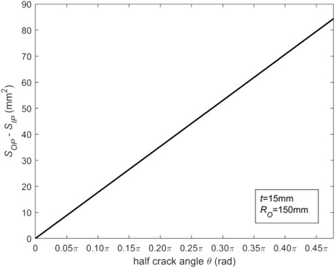
FIGURE 16. Variation of SIP - SOP as a function of θ.
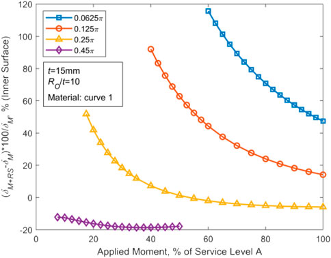
FIGURE 17. Variation of the inner wall ΔCOD in terms of the stress level for various θ in the case of t = 15 mm, RO/t = 10, and material curve 1.
6.2 Validation of the COD analysis formula in the GE/EPRI method
The COD results based on the WRS’s expressions in Table 1 are compared with the results from GE/EPRI and NUREG/CR-6837 analysis in this study for the case of t = 15 mm, θ = 0.25π, RO/t = 5, as illustrated in Figure 18. (Wichman and Lee, 1990; U.S.N.R.C. NUREG -1061, 1984; Scott R, 2005). It is revealed that both the GE/EPRI method and the NUREG/CR-6837 method overestimated COD. The former is for the external load stress less than 60 MPa and the latter is for stress lower than 30 MPa. Such deviation in prediction is detrimental to LBB technology applications.
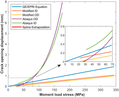
FIGURE 18. Validation of the GE/EPRI and NUREG/CR-6837 approaches.
6.3 Effect of WRS on the morphology of crack channel in the leakage rate analysis model
In the Henry-Fauske two-phase flow analysis model, it is generally assumed that the cross-sectional area of a flow channel changes uniformly and linearly along the axial direction, so that in Eq. 5 the pressure loss terms associated with the cross-sectional area of the inlet and outlet of the channel can be derived.
Based upon the selected case where WRS has the greatest effects on CODs of the crack in thin-walled and thick-walled pipes (t = 15 mm, θ = 0.0625π, Ro/t = 5 or t = 40 mm, θ = 0.45π, Ro/t = 20, and the material performance parameters obey curve one in Table 1), displacement of the crack channel axis at various stress levels are calculated, and the achieved results are fitted and shown in Figures 19, 20.
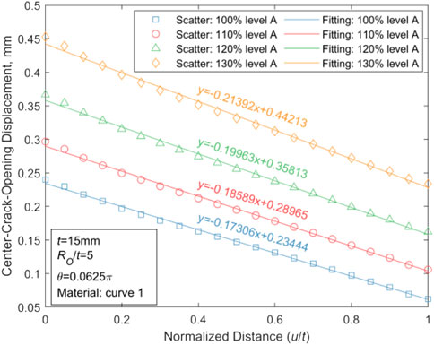
FIGURE 19. Fitting results of the axial displacement of the CTWC in thin-walled pipes.
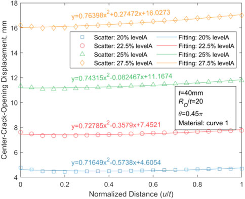
FIGURE 20. Fitting results of the axial displacement of the CTWC in thick-walled pipes.
Using the MATLAB software, we analyze the linear dependencies between u/t and COD for the plotted results of thin-walled pipes in Figure 19 with the least square method. The estimates of R2 and F statistics, and p error variance are provided in Table 5.
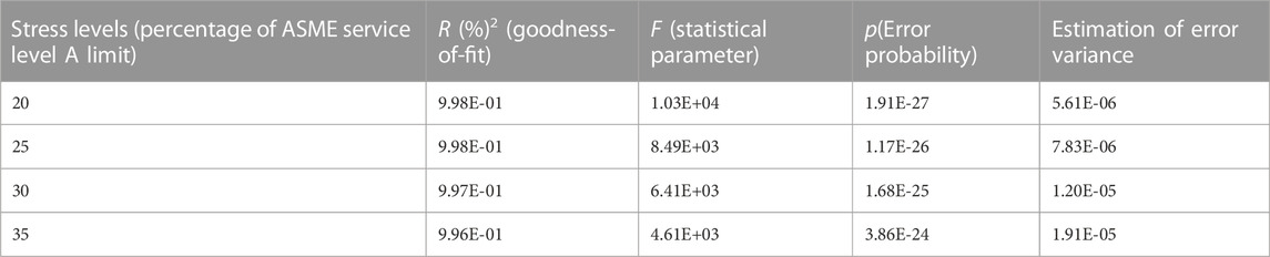
TABLE 5. Linear fitting results of the CTWC axial displacement in thin-walled pipes.
For thin-walled pipes, R2 values are close to one at all four stress levels in Table 6, and p values are below the default significance level of 0.05. Hence, there is a strong linear regression between the dependent variable COD and the independent variable u/t. For thick-walled pipes, such relationship could be fitted as a weak quadratic function, as shown in Figure 20.
In the scope of this paper, the fitting function of the CTWC axis in thin-walled pipes is studied by choosing the parameters with the most obvious WRS effect. The obtained results show that the axis of the thin-walled pipe is linear while the axis of the thick-walled pipe is non-linear.
7 Conclusion
In the present work, the finite element method was employed to establish a three-dimensional elastic-plastic numerical analysis model of pipes with CTWC. The COD results of the cracks for various pipe sizes, crack angles, material properties, and stress levels under typical WRS are acquired and compared with those without WRS. Combined with the results of the COD analysis, the influence of key parameters of CTWC channel morphology in terms of external load were examined. Furthermore, the effect of WRS on the medium leakage rate of piping in LBB technology was studied by Henry and Fauske’s two-phase flow analysis model with uniform and unbalanced flow. Finally, some technical issues are discussed. The findings are summarized as follows:
(1) Under the same WRS, the effect of the pipe wall thickness on COD could be ignored. For thin-walled pipes, the shorter the crack, the greater the impact of WRS on COD. For thick-walled pipes, the longer the crack, the greater the impact of WRS on COD. The effect of WRS on COD of thin-walled pipes was significantly different when the outer diameter of the pipe varied, while such effect was unobvious in the condition of thick-walled pipes. When the material properties varied, the effect of WRS on COD was obvious, especially in the inner wall.
(2) WRS does not have an obvious effect on the factors K and nt. In the presence of WRS, COA is reduced by at least 37% and 80% respectively for thin-walled and thick-walled pipes. Similarly, rOI was reduced, particularly for small diameter thin-walled pipes. For both COA and ROI, the effect of WRS lessens with the growth of the external load.
(3) For the analysis object selected in this paper, before the instability of CTWC, WRS can significantly reduce the leakage rate of the medium. For example, the leakage rate is reduced by at least 46.55% and 14.46% for thin-walled and thick-walled pipes, respectively.
(4) For the simplified envelope WRS recommended by ASME (Katsuyama et al., 2010), although the inner wall of the thin-walled pipe is subjected to tensile stress when Ro/t is large or the crack angle is small, the WRS could still reduce COD of the inner wall. The non-zero intercept of the COD curve at the inner wall point of CTWC in the absence of the external load found in the reference NUREG/CR-6837 does not exist (that is, when the external load vanishes, the displacement of the inner wall point becomes positive).
(5) Using the simplified envelope value of WRS recommended by ASME (Katsuyama et al., 2010), the obtained results showed that the flow channel axis of TWC in the thick-walled pipe may be closer to the quadratic function curve.
In the present work, stress loading is exploited to simulate the effect of WRS via the finite element analysis. In fact, strain loading is better than stress loading because it could take into account the change of strain release rate in various parts of the structure during the process of the CTWC formation. However, except for the stress loading method, there are almost no practical and simple loading strategies in the FEA analysis. Therefore, how to realize reasonable strain loading and compare the results with stress loading is what to be explored further.
For experimental studies of the effects of WRS on COD of CTWC under different external loading levels, the technical links involved are more complex, because such tests not only include non-destructive and continuous monitoring of WRS under various welding processes, but also need to consider the monitoring of the WRS variations in the preparation process of CTWCs, as well as the demand to achieve micro loading of external loads and accurate measurement of crack closure states. To achieve this goal, unfortunately so far no mature and reliable solutions have been developed yet. (Moody, 1965; Rahman et al., 1998a; Bourga, 2017).
Data availability statement
The original contributions presented in the study are included in the article/supplementary material, further inquiries can be directed to the corresponding author.
Author contributions
ZL proposed conception and design of the study, did leakage analysis and wrote and edited the first draft of the manuscript. SZ did finite element analysis and plot the illustrations. QM supervised the findings of this work. XZ revised it critically for important intellectual content and revised draft of the manuscript. All authors discussed the results and contributed to the final manuscript.
Funding
This work is supported by China State Key Laboratory of Nuclear Power Safety Monitoring Technology and Equipment with grant number 007-EC-AB-2020.
Acknowledgments
The authors would also like to express their gratitude to EditSprings (https://www.editsprings.cn) for their linguistic services.
Conflict of interest
Author ZL was employed by the China Nuclear Power Engineering Co., Ltd.
The remaining authors declare that the research was conducted in the absence of any commercial or financial relationships that could be construed as a potential conflict of interest
Publisher’s note
All claims expressed in this article are solely those of the authors and do not necessarily represent those of their affiliated organizations, or those of the publisher, the editors and the reviewers. Any product that may be evaluated in this article, or claim that may be made by its manufacturer, is not guaranteed or endorsed by the publisher.
References
Abdollahian, D., and Chexal, B. (1983). Calculation of leak rates through cracks in pipes and tubes. Campbell, CA: EPRI NP-3395.
Anderson, T. L., and Glinka, G. (2006). A closed-form method for integrating weight functions for part-through cracks subject to Mode I loading. Eng. Fract. Mech. 73 (15), 2153–2165. doi:10.1016/j.engfracmech.2006.04.027
Benson, M. L., Brust, F. W., Kurth, R. E., and Broussard, J. E. (2014). “Weld residual stress inputs for a probabilistic fracture mechanics code [Z],” in Proceedings of the ASME 2014 Pressure Vessels and Piping Conference, Anaheim, California, USA, July 2014. doi:10.1115/PVP2014-28030
Bhandari, S., Faidy, C., and Acker, D. (1992). Computation of leak areas of circumferential cracks in piping for application in demonstrating leak-before-break behaviour. Nucl. Eng. Des. 135 (2), 141–149. doi:10.1016/0029-5493(92)90216-i
Bourga, R., Moore, P., Janin, Y. J., Wang, B., and Sharples, J. (2015). Leak-before-break: Global perspectives and procedures. Int. J. Press. Vessels Pip. 129, 43–49. doi:10.1016/j.ijpvp.2015.02.004
Bourga, R. (2017). The mechanism of leak-before-break fracture and its application in engineering critical assessment [D]. Ann Arbor: Brunel University United Kingdom.
Brust, F. W., Kurth, R. E., Shim, D. J., and Rudland, D. L. (2011). “Strategies for treating weld residual stresses in probabilistic fracture mechanics codes,” in Proceedings of the ASME 2011 Pressure Vessels and Piping Conference, Baltimore, Maryland, USA, July 2011. F[C].
Coules, H., and Smith, D. (2015). “Upper bound estimates of the contribution of an unknown residual stress field to stress intensity factor,” in Proceedings of the ASME 2015 Pressure Vessels and Piping Conference, July 2015. F[C]. V06AT06A011.
Dehaghi, E. M., Moshayedi, H., Sattari-Far, I., and Arezoodar, A. F. (2017). Residual stresses due to cladding, buttering and dissimilar welding of the main feed water nozzle in a power plant reactor. Int. J. Press. Vessels Pip. 152, 56–64. doi:10.1016/j.ijpvp.2017.05.009
EPRI (1986). Evaluation of flaws in austenitic steel piping [R]. Washington: Electric Power Research Institute.
Fan, J., Dong, D., Chen, L., Chen, X., and Guo, X. (2015). Weight Function Method for computations of crack face displacements and stress intensity factors of center cracks. Frat. Ed. Integrità Strutt. 9 (33), 463–470. doi:10.3221/igf-esis.33.51
France, C. C., Green, D., Sharples, J. K., and Chivers, T. (1997). New stress intensity factor and crack opening area solutions for through-wall cracks in pipes and cylinders. ASME Press. Vessels Pip. Div. Publ. PVP 350, 143–149.
Ghadiali, N., Wilkowski, G., Rahman, S., and Choi, Y. H. (1996). Deterministic and probabilistic evaluations for uncertainty in pipe fracture parameters in leak-before-break and in-service flaw evaluations [R]. Washington, DC: US Nuclear Regulatory Commission. (United States). Div.
Gill, P., Sharples, J., and Budden, P. (2015). “Leakage rates through complex crack paths using an ODE method,” in Proceedings of the ASME 2015 Pressure Vessels and Piping Conference, Boston, Massachusetts, USA, July 2015. F[C]. V06AT06A081.
Huang, Y., Wang, X., and Duan, X. (2020). Evaluation of crack opening displacement of through-wall circumferential-cracked pipe using direct weight function method. Theor. Appl. Fract. Mech. 108, 102595. doi:10.1016/j.tafmec.2020.102595
Huang, Y., and Zhou, W. (2020). Impacts of residual stresses on J-integral for clamped SE(T) specimens with weld centerline cracks. Theor. Appl. Fract. Mech. 107, 102511. doi:10.1016/j.tafmec.2020.102511
Irwin, G. R. (1960). Plastic zone near a crack and fracture toughness. Sagamore Res. Conf. Proc. 4, 63–78.
Itoh, H., Katsuyama, J., and Onizawa, K. (2008). “A probabilistic evaluation model for welding residual stress distribution at piping joint in probabilistic fracture mechanics analysis [Z],” in Proceedings of the ASME 2008 Pressure Vessels and Piping Conference, Chicago, Illinois, USA, July 2008, 1137–1142. doi:10.1115/PVP2008-61421
Katsuyama, J., Itoh, H., Tobita, T., and Onizawa, K. (2010). Probabilistic structural integrity assessment based on uncertainty of weld residual stress at the piping butt-welds of nuclear reactor components. Proc. Weld. Soc. 28 (2), 193–202. doi:10.2207/qjjws.28.193
Kiciak, A., Glinka, G., and Burns, D. J. (2003). Calculation of stress intensity factors and crack opening displacements for cracks subjected to complex stress fields. J. Press. Vessel Technol. Trans. ASME 125 (3), 260–266. doi:10.1115/1.1593080
Klecker, R., Brust, F., and Wilkowski, G. (1986). NRC leak before break (LBB.NRC) analysis for throughwall cracked pipes under axial plus bending loads. Columbus, Ohio.
Kumar, V., and German, M. D. (1988). Elastic-plastic fracture analysis of through-wall and surface flaws in cylinders. Schenectady, New York.
Lewis, T., and Wang, X. (2008). The T-stress solutions for through-wall circumferential cracks in cylinders subjected to general loading conditions. Eng. Fract. Mech. 75 (10), 3206–3225. doi:10.1016/j.engfracmech.2007.12.001
Lukes, R. G. (2013). Predicting the crack response for a pipe with a complex crack [D]. Los Angeles, CA: University of South Carolina.
Lyellsanders, J. (1982). Circumferential through-cracks in cylindrical shells under tension. J. Appl. Mech. Trans. ASME 49 (1), 103–107. doi:10.1115/1.3161948
Macurova, K., Tichy, R., and Strnadel, B. (2010). “Modification of leak before break criterion with focus on the residual stress,” in Proceedings of the ASME 2010 Pressure Vessels and Piping Division/K-PVP Conference, Bellevue, Washington, USA, July 2010. F[C].
Mångård, D., and Hannes, D. (2020). Estimates ofJ-integral and COD for circumferential through wall cracks under global bending including the effect ofpipe end restraint [R]. Solna: Tobias Bolinder Kiwa Inspecta Technology AB.
Mccluskey, R. J. A., Sherry, A. H., and Goldthorpe, M. R. (2011). “Characterisation of the residual stress field and mechanical properties of a narrow-gap girth-welded stainless steel pipe and subsequent application to a numerical model,” in Proceedings of the ASME 2011 Pressure Vessels and Piping Conference, Baltimore, Maryland, USA, July 2011. F[C].
Miessi, G. A., Riccardella, P. C., and Jing, P. (2011). “Effects of weld overlays on leak-before-break margins,” in proceedings of the ASME 2011 Pressure Vessels and Piping Conference, Baltimore, Maryland, USA, July 2011. F[C].
Mirzaee-Sisan, A., and Wu, G. (2019). Residual stress in pipeline girth welds- A review of recent data and modelling. Int. J. Press. Vessels Pip. 169, 142–152. doi:10.1016/j.ijpvp.2018.12.004
Moody, F. J. (1965). Maximum flow rate of a single component, two-phase mixture. J. Heat. Transf. 87, 134–141. doi:10.1115/1.3689029
Namburu, S. D., Chebolu, L. R., Subramanian, A. K., Prakash, R. V., and Sasikala, G. (2018). Influence of weld residual stresses on ductile crack behavior in AISI type 316LN stainless steel weld joint in Proceedings of the ASME Pressure Vessels Piping Div Publ PVP, July 2018. F[C].
Norris, D. (1987). PICEP (pipe crack evaluation computer program). Palo Alto, CA [R]: EPRI NP-3596-SR.
Paris, P. C., and Tada, H. (1983). Application of fracture-proof design methods using tearing-instability theory to nuclear piping postulating circumferential through-wall cracks. St. Louis, MO.
Rahman, S., Ghadiali, N., Paul, D., and Wilkowski, G. (1995). Probabilistic pipe fracture evaluations for leak-rate-detection applications [R]. Washington, DC: US Nuclear Regulatory Commission. (United States). Div.
Rahman, S., Brust, F., Ghadiali, N., Wilkowski, G., and Miura, N. (1997). “Recent evaluations of crack-opening-area in circumferentially cracked pipes [Z],” in Conference: Seminar on leak before break in reactor piping and vessels, Lyon (France), 9-11 Oct 1995; Other Information: PBD: Apr 1997; Related Information: Is Part Of Proceedings of the seminar on leak before break in reactor piping and vessels; Faidy, C [Electricite de France, Villeurbanne (France)]; Gilles, P [ed] [Framatome, Paris (France)]; PB: 773 p, Lyon, France, 299–314. Medium: X; Size.
Rahman, S., Brust, F. W., Ghadiali, N., and Wilkowski, G. (1998). Crack-opening-area analyses for circumferential through-wall cracks in pipes—Part I: Analytical models. Int. J. Press. Vessels Pip. 75 (5), 357–373. doi:10.1016/s0308-0161(97)00081-1
Rahman, S., Ghadiali, N., Wilkowski, G. M., Moberg, F., and Brickstad, B. (1998). Crack-opening-area analyses for circumferential through-wall cracks in pipes—Part III: Off-center cracks, restraint of bending, thickness transition and weld residual stresses. Int. J. Press. Vessels Pip. 75 (5), 397–415. doi:10.1016/s0308-0161(97)00083-5
Scott, P., Olson, R. J., and Wilkowski, G. (2002). Development of technical basis for leak-before-break evaluation procedures [M]. Columbus, Ohio: Division of Engineering Technology, Office of Nuclear Regulatory Research.
Scott R, P. (2005). The Battelle integrity of nuclear piping (BINP) program final report: Appendices(NUREG/CR-6837) [R].O.
Shim, D-J., Kurth, E., Brust, F., Wilkowski, G., Csontos, A., and Rudland, D. L. (2009). “Crack-opening displacement and leak-rate calculations for full structural weld overlays,” in Proceedings of the ASME 2009 Pressure Vessels and Piping Conference, Prague, Czech Republic, July 2009. F[C].
Song, S., and Dong, P. (2015). “Analysis of residual stresses in pipe seam welds and a proposed residual stress profile estimation method,” in Proceedings of the ASME 2015 Pressure Vessels and Piping Conference, Baltimore, Maryland, USA, July 2011. F[C]. V06BT06A068.
Standard, B. (2015). BS 7910: 2013+ A1: 2015 guide to methods for assessing the acceptability of flaws in metallic structures [J]. London, UK: BSI Stand Publ.
Takahashi, Y. (2002). Evaluation of leak-before-break assessment methodology for pipes with a circumferential through-wall crack. Part III: Estimation of crack opening area. Int. J. Press. Vessels Pip. 79 (7), 525–536. doi:10.1016/s0308-0161(02)00038-8
Wallin, K., and Nevasmaa, P. (1997). Structural integrity assessment procedures for European industry (SINTAP) [Z]. Rotherham, Yorkshire: Sub-Task.
Webster, G. A., Davies, C. M., and Nikbin, K. M. (2014). Prediction of creep crack growth in the presence of residual stress. Mater. A. T. High. Temp. 28 (3), 165–171. doi:10.3184/096034011x13119610349738
Wei, L., He, W., and Smith, S. (2011). “The effects of loadings on welding residual stresses and assessment of fracture parameters in a welding residual stress field,” in Proceedings of the ASME 2011 Pressure Vessels and Piping Conference, Baltimore, Maryland, USA, July 2011. F[C].
Wichman, K., and Lee, S. (1990). Development of USNRC standard review plan 3.6.3 for leak-before-break applications to nuclear power plants. Int. J. Press. Vessels Pip. 43 (1), 57–65. doi:10.1016/0308-0161(90)90092-v
Yang, J., Park, C., and Huh, N. (2011). Estimates of mechanical properties and residual stress of narrow gap weld for leak-before-break application to nuclear piping. J. Press. Vessel Technology-transactions Asme 133 (2), 021403. doi:10.1115/1.4002279
Young, B. A., Olson, R. J., and Kerr, M. (2012). Advances in COD equations: Circumferential through-wall cracks. F[C].
Zang, W., Gunnars, J., Mullins, J., Dong, P., and Hong, J. H. (2009). Effect of welding residual stresses on crack opening displacement and crack-tip parameters [R]. Sweden.
Zhenshun, L., Sheng, Z., and Qing, M. (2022). Research on the closure effect of circumferential through-wall cracks in welds of stainless steel nuclear piping under typical residual stress[J/OL]. Nucl. Power Eng., 1–7.
Zhong, X., and Ban, H. (2022a). Crack fault diagnosis of rotating machine in nuclear power plant based on ensemble learning. Ann. Nucl. Energy 168, 108909. doi:10.1016/j.anucene.2021.108909
Zhong, X., and Ban, H. (2022b). Pre-trained network-based transfer learning: A small-sample machine learning approach to nuclear power plant classification problem. Ann. Nucl. Energy 175, 109201. doi:10.1016/j.anucene.2022.109201
Keywords: leak-before-break (LBB), welding residual stress (WRS), crack opening displacement (COD), leakage rate, piping, through-wall crack (TWC), stainless steel
Citation: Liu Z, Zhang S, Mao Q and Zheng XY (2023) Role of welding residual stress in stainless steel piping with application of the leak-before-break technology. Front. Energy Res. 10:1079476. doi: 10.3389/fenrg.2022.1079476
Received: 25 October 2022; Accepted: 05 December 2022;
Published: 24 January 2023.
Edited by:
Jun Wang, University of Wisconsin-Madison, United StatesReviewed by:
Guohua Wu, Harbin Institute of Technology, ChinaSijuan Chen, Shenzhen University, China
Yun Luo, China University of Petroleum, China
Copyright © 2023 Liu, Zhang, Mao and Zheng. This is an open-access article distributed under the terms of the Creative Commons Attribution License (CC BY). The use, distribution or reproduction in other forums is permitted, provided the original author(s) and the copyright owner(s) are credited and that the original publication in this journal is cited, in accordance with accepted academic practice. No use, distribution or reproduction is permitted which does not comply with these terms.
*Correspondence: Xiang Yuan Zheng, emhlbmcueGlhbmd5dWFuQHN6LnRzaW5naHVhLmVkdS5jbg==
†These authors have contributed equally to this work