 Chuanming Xi
 Wei Zhang
- Research Institute of Engineering Technology, PetroChina Xinjiang Oilfield Company, Karamay, China
Drilling a deep vertical well at a low cost is very important for accelerating the exploration and development of oil and gas resources. Vertical drilling BHA design is the key to drill a vertical well, however the BHA design is still an art not science in some formation. In this paper, a new mechanical model of bent-housing motor BHA is established, a build rate prediction method considering formation properties is presented and a BHA design method considering formation uncertainties is proposed. The evaluation results of vertical drilling BHA show that formation dip, formation anisotropy and hole diameter expansion are the main factors affecting pendulum BHA performance, and formation dip, formation anisotropy, hole diameter expansion and the distance from the upper stabilizer to the bit are the main factors affecting bent-housing motor BHA performance. The case study of the proposed BHA design method demonstrates that hole diameter expansion is very important for vertical drilling BHA performance, and should be taken in to account during the design process. The models and method proposed in this paper is helpful in maintaining verticality and reduce drilling cost.
1 Introduction
Drilling a vertical wildcat well is very important for evaluating conventional and unconventional oil and gas reservoirs, and reducing the drilling cost can accelerate the exploration and development. However, as the vertical wildcat well gets deeper and deeper, the rate of penetration (ROP) gets slower, and the drilling gets more and more expensive. Maintaining verticality is one of the reasons of high drilling cost. In most cases, weight on bit (WOB) is limited to a small value to drill a vertical well, and ROP is therefore repressed.
Designing an appropriate vertical drilling bottom hole assembly (BHA) for a given formation is very important. To achieve this goal, a BHA mechanical model and a bit-rock interaction model are usually needed. The BHA mechanical model is used to calculate the side force acting on the bit and bit tilt angle. The bit-rock model is used to predict bit advancement direction by taking bit side force, bit tilt angle and formation properties into account. Accurate BHA modeling and bit-rock interaction modeling are the cores of vertical drilling BHA design.
Several BHA modeling methods are available, including finite element methods (Millheim et al., 1978; Williams et al., 1989; Neubert, 2005; Wilson, 2018; Greenwood et al., 2020), beam-column theory (Bai, 1982; Bai and Lin, 1985; Bai et al., 1989) and other numerical methods (Menand et al., 2006; Menand et al., 2016; Wang et al., 2022). The finite element methods can deal with more complex BHA structures, but some of them have problems in solving initial wellbore curvature and may produce paradoxical results (Wilson, 2017). The beam-column theory is accurate in analyzing BHA, but the equilibrium equations are not universal and must be established according to the specific BHA structure. Other numerical methods directly solving equilibrium of forces and moments also has problems in generalization of analyzing BHA.
A bit-rock interaction model can be used to predict drilling direction. Ho (1987) proposed a bit-rock interaction model, which can consider the effects of bit side force, bit tilt angle, formation dip, formation anisotropy and bit anisotropy. Menand et al. (2004) study how bit profile and gauges affect well trajectory. Shi et al. (2017) combine Ho’s bit-rock model and beam-column theory to predict BHA build rate.
Although there are many BHA and bit-rock models, the factors affecting vertical drilling BHA performance are still not known. For example, there is no guide of how to choose a vertical drilling BHA in a formation prone to hole enlargement. In this paper, the mechanical models of bent-housing motor BHA are derived based on beam-column theory, and a vertical drilling BHA design method is proposed, which considers formation uncertainties, including unknown formation dip, formation anisotropy and hole enlargement.
2 Methods
2.1 Mechanical models of vertical drilling bottom hole assembly
There are three kinds of commonly used vertical drilling BHAs, namely pendulum BHA, bent-housing motor BHA and vertical drilling system (VDS). In a pendulum BHA, a stabilizer is placed 15–22 m above the bit, such as Φ215.9 mm bit + Φ158.8 mm drill collar*2 + Φ215 mm stabilizer + Φ158.8 mm drill collar*19. Bent-housing motor BHA used with two stabilizers can also reduce well deviation, such as: Φ215.9 mm bit + Φ172 mm bent-housing motor (0.75° bent angle) + Φ158.8 mm short drill collar*1 + Φ214 mm stabilizer + Φ158.75 mm drill collar*17. VDS is a special version of rotary drilling system (RSS), and is often considered as the most powerful vertical drilling tool, but its cost is far greater than that of pendulum and bent-housing motor BHA.
The mechanical model of pendulum BHA can be found in many textbooks, VDS is assumed to be always successful in correcting deviation, and thus only the mechanical model of the bent-housing motor is derived in this section. The beam-column theory is used to establish the mechanical analysis model of the bent-housing motor BHA. Figure 1 is a simplified mechanical model of the bent-housing BHA, which consists of a lower stabilizer, a bent-housing motor, a short collar and an upper stabilizer.
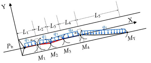
FIGURE 1. Mechanical model of the bent-housing motor BHA.
In the mechanical model, the bent-housing motor is cut off at the bend, and there are therefore five beam sections with linear buoyant weight q1∼q5, length L1∼L5 and moment of area I1∼I5. In Figure 1, there are five bending moments M1, M2, M3, M4 and MT. The equilibrium equations can be obtained by setting two rotation angles equal to each other at the joint.
The three-moment equation between the first and second beam can be written as:
Where Y1 and Y2 are the deflections at the lower stabilizer and bend point, respectively; E is the elasticity modulus; X(u), Y(u) and Z(u) are three rotation amplification factors.
The rotation amplification factors can be calculated by the following equations,
The bent-housing motor is cut off at the bend point, which results in two new unknown variables, namely the internal bending moment M2 and the deflection Y2. According to the continuity of rotation angle and shear force at the bend, two three-moment equations can be obtained.
Where P2 and P3 are the axial forces in the second and third beams, respectively; γ is the bend angle; Y3 is the deflection at the upper end of the motor.
Similarly, two equations can be obtained at the joint of motor and short collar:
Where P4 is the axial force at the short collar; Y4 is the deflection at the upper stabilizer.
A three-moment equation can be obtained at the upper stabilizer,
Where Y5 is the deflection at the upper tangent point, and can be calculated according to collar diameter and wellbore diameter; MT is the moment at the upper tangent point, and can be calculated according to known wellbore curvature.
In addition, at the upper tangent point, the three bending moment equation can be obtained:
After solving Eqs 1–11, getting M1 and Y1, the bit side force Nb and bit tilt angle Aα can be calculated:
It should be pointed out that the new model does not consider drill string buckling, because there are two stabilizers and the drill string between them is too short to buckle.
2.2 Build rate prediction method
Bit side force or bit tilt angle alone calculated by the BHA mechanics model cannot determine the drilling direction of the bit, and formation properties must be also taken into account. In this section, the drilling trend angle method (Shi et al., 2017) is adopted to predict build rate, but some equations in Shi’s paper are erroneous, and the correct solution of drilling trend angle is presented.
Figure 2A shows the drilling trend of bit in formation. A bottomhole coordinate system O1-X1Y1Z1 is established at the bit, The actual drilling direction of the bit is along the X1 axis, the direction of the wellbore high side is the direction of the Z1 axis, and the direction of the Y1 axis is determined by the right-hand rule. The vector er represents the drilling trend direction of the bit, and the angle between the vector er and the X1 axis is defined as the drilling trend angle Ar.
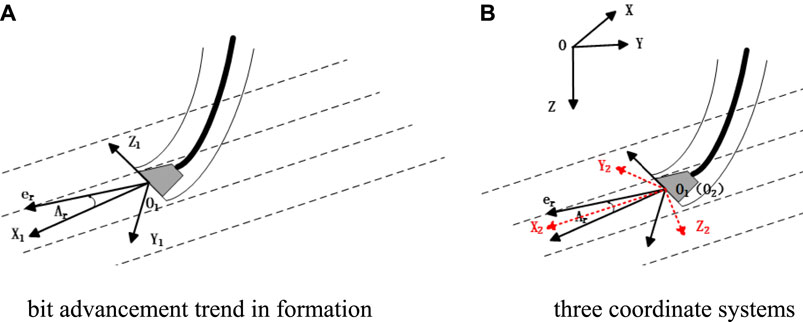
FIGURE 2. Schematic of bit advancement trend in formation and three coordinate systems (A) bit advancement trend in formation (B) three coordinate systems.
Assuming a wellbore curvature K0, and calculating Ar, if Ar comes to zero, the drilling trend is just balanced, and K0 can be equivalent to BHA build rate. Otherwise, the drilling trend is not balanced, and the hole curvature must be re-assumed and the drilling trend angle Ar must be calculated until it comes to zero. To sum up, the basic idea of drilling trend method predicting the BHA build rate is that the borehole curvature when the drilling trend angle is close to zero is equivalent to BHA build rate.
In order to consider the effects of bit anisotropy, formation anisotropy, formation dip and other factors on drilling trend angle, the rock-bit interaction model by Ho (1987) is adopted. This model assumes that the formation is isotropic in transverse direction, and the drilling direction can be expressed as:
Where Ib and Ir are the bit and formation anisotropy factors; Aaf is the angle between the resultant bit force direction and the axial direction of the bit; Ard is the angle between the drilling direction and the normal direction of the formation bed; rN is the drilling efficiency under general condition; er, ef, ea and ed are the unit vectors of drilling trend direction, bit force direction, bit axis direction, and formation normal direction, respectively.
To solve Ar, it is necessary to establish the transformation relationship between bit parameters and formation parameters. As shown in Figure 2B , a surface coordinate system O-XYZ is established, in which the X-axis points to the north direction, the Y-axis points to the east direction, the Z-axis points to the gravity direction, and a formation coordinate system O2-X2Y2Z2 is also established, in which the X2 axis points to the downward dip direction of the formation, the downward normal direction of the formation is the direction of the Z2 axis, and the Y2 axis is determined by the right-handed rule.
The transformation matrix from surface coordinate system to bottomhole coordinate system is as follows:
Where, α and φ represent inclination and azimuth at the bit, respectively.
The transformation matrix from surface coordinate system to formation coordinate system is as follows:
Where β and θ represent dip angle and dip orientation, respectively (dip orientation is defined as the azimuth of downdip direction of formation bed).Setting,
getting,
Defining
In the bottomhole coordinate system, ef and ea calculated according to the bit side force and bit tilt angle can be expressed as:
Defining
The unit vector ed of the formation normal direction can be expressed as:
The unit vector systems in Eqs 19–22 were converted to the bottomhole coordinate system and substituted into rock-bit interaction model. The following results could be obtained:
Where S1 = IbIrcosαf +Ir(1–Ib) cosAaf cosαa; S2 = IbIrcosβf + Ir (1–Ib) cosAafcosβa; S3 = IbIrcosγf + Ir (1–Ib) cosAaf cosγa.
The drilling trend angle Ar can be obtained by substituting the bit side force and bit tilt angle into Eqs 23–25, and converting the calculated results to the bottomhole coordinate system, which can be expressed as follows:
2.3 Design method of vertical drilling BHA considering uncertainties
The factors that affect the anti-deviation ability of BHA can be grouped into two types, namely formation factors and adjustable factors. The formation factors can hardly be changed, including formation dip, formation anisotropy and hole enlargement rate. Adjustable factors include WOB and BHA structure parameters, which can be controlled. The optimal design of BHA is the process of changing adjustable factors to satisfy the requirement of formation factors and to drill a vertical well.
The optimal design of BHA includes two interactive processes, that is, the selection of BHA type and the design of specific structural parameters. On the one hand, optimized BHA should have good anti-deviation ability, and on the other hand the selected BHA should keep drilling cost as low as possible. Therefore, this paper applies a drilling cost prediction method to calculate the expected cost of different types of vertical drilling BHA in a bit life cycle, and selects the type and structure of the BHA based on the principle of minimizing the expected cost.
The cost of a vertical drilling BHA over the bit life can be expressed by the following formula (Si et al., 2009),
Where cm1 is the daily drilling cost, include labor cost, depreciation cost, management cost, material consumption cost and maintenance cost; t is the drilling time; cm2 is the cost of the BHA; cm3 is the extra cost of drilling at a small WOB if the designed vertical drilling BHA fail; Pj is the probability of effective anti-deviation of the BHA.
3 Results and discussions
Different types of vertical drilling BHA have different main control factors that restrict their ability to prevent deviation. In this section, the main control factors affecting the anti-deviation ability of pendulum BHA and bent-housing motor BHA are analyzed. Besides, the proposed vertical drilling BHA design method is illustrated using a case study.
3.1 Factors affecting pendulum bottom hole assembly performance
Taking the following pendulum BHA as an example, the BHA structure is: Ф215.9 mm bit + Ф172 mm straight-housing motor + Ф210 mm stabilizer + Ф158.8 mm collar * 24. The pendulum BHA was run in vertical well A at well depth of 3,480 m, and WOB was controlled within 40–60 kN. However, the well inclination starts to increase from 3,660 m, and reaches 4° at a depth of 4,000 m. Seismic data shows the formation dip in the third spud hole is about 5.5°.
In order to analyze the cause of well deviation, rotary drilling build rates of the pendulum BHA under different drilling parameters and formation parameters are calculated. According to the geological design of the well and the drilling engineering data and formation data of offset wells, the bit anisotropy factor Ib is set to 0.2, the formation anisotropy factor Ir is set to 0.98, the formation dip is set to 6°, the initial inclination is set to 3°, and the WOB is set to 50 kN. The WOB, formation dip and formation anisotropy factor are varied to calculate the BHA build rate.
Figure 3 shows that with the increase of WOB, the pendulum BHA build rate increases and keeps positive at all WOB, which means that the pendulum BHA does not have the ability to prevent well deviation. Figure 4 shows that the pendulum BHA build rate linearly increase with the increase of formation dip. If formation anisotropy factor is equal to 1, the formation has no anisotropy. According to this definition and Figure 5, the pendulum BHA build rate almost linearly increases with the increase of formation anisotropy.
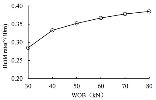
FIGURE 3. Pendulum BHA build rates at different WOB.
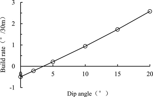
FIGURE 4. Pendulum BHA build rates at different formation dip.
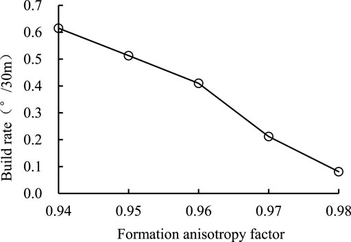
FIGURE 5. Pendulum BHA build rates at different formation anisotropy factor.
Adjusting the pendulum BHA structure and calculating the build rate, the results are shown in Figures 6, 7. From Figure 6, with the increase of the distance from stabilizer to bit, the build rate first decreases and then gradually tends to be stable, and the anti-deviation ability reaches the maximum when the distance is about 19 m. According to Figure 7, with the increase of stabilizer outer diameter, the build rate decreases, but the values are still positive, which means the pendulum BHA still increase inclination.
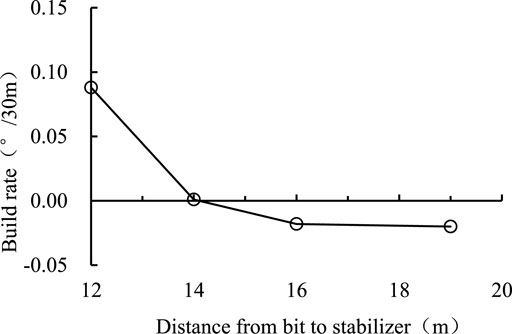
FIGURE 6. Pendulum BHA build rates with different stabilizer positions.

FIGURE 7. Pendulum BHA build rates with different stabilizer diameters.
The change in the build rate after the wellbore expansion is calculated, and the results are shown in Figure 8. The build rate increases rapidly after the diameter expansion occurs, and when the well diameter expansion rate reaches 100%, the build rate increases by five times. According to caliper logging, the diameter expansion rate can reach 160% in some section. Therefore, diameter expansion rate must be considered during the vertical drilling BHA design.
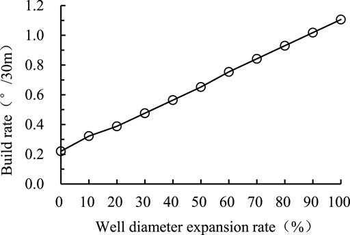
FIGURE 8. Pendulum BHA build rates with different well diameter expansion rates.
Based on the calculated results, the reason why the pendulum BHA failed is that the distance from the stabilizer to the bit is too short. In summary, the main factors affecting the anti-deviation ability of pendulum BHA are formation dip, formation anisotropy and well diameter expansion. Besides, the distance from stabilizer to bit, stabilizer diameter and WOB also play important roles.
3.2 Factors affecting bent-housing motor bottom hole assembly performance
The structure of the bent-housing motor BHA is as follows: Φ215.9 mm bit + Φ172 mm 0.75° bent-housing motor (with stabilizer) + Φ158.8 mm drill collar*1 + Φ214 mm stabilizer + Φ158.8 mm drill collar*17. This bent-housing motor BHA is used in vertical well B, with drilling fluid density 1.3 g/cm3 and WOB 60 kN. The well inclination increases to 2° at 2000 m and reaches 4° at 2,550 m. The average formation dip of this drilling section is about 3.5°.
In the calculations of rotary drilling build rates, according to data offset wells, the bit anisotropy factor Ib equals 0.2, the formation anisotropy factor Ir equals 0.95, the inclination angle of the well is 3°, and WOB is 60 kN.
Figure 9 shows that the build rate of linearly increases with increasing WOB, but the growth rate is very low, and the build rate only changes 0.1°/30 m within 40–100 kN WOB, which indicates that the effect of WOB is not significant for bent-housing motor BHA.

FIGURE 9. Bent-housing motor BHA build rates at different WOB.
Figure 10 shows that as the formation dip increases the build rate of the bent-housing motor increases and the growth rate also increases, indicating that the formation dip has a greater influence. Besides, it can be seen that this bent-housing motor BHA cannot correct well deviation in the formation with a dip angle of 3.5°.
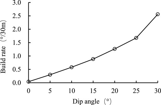
FIGURE 10. Bent-housing motor BHA build rates at different dip angle.
The diameter control of this well is good, but a certain degree of well diameter expansion occurs in some sections, and the well diameter expansion rate reaches 30% at a depth of about 2,150 m. The effect of the well diameter expansion on the build rate is calculated and the results are shown in Figure 11, which shows that when the well diameter expansion reaches 30%, the build rate increases 6 times compared to 5% expansion. Comparing the inclination data with the well diameter data, it can be found that the actual build rate of is larger in the diameter expanded section.
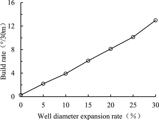
FIGURE 11. Bent-housing motor BHA build rates with different diameter expansion.
Changing the distance of the upper stabilizer to bit, calculating the build rate, the results are shown in Figure 12. Figure 12 illustrates that as the distance from the bit to the upper stabilizer increases, the anti-deviation capability of the BHA decreases. This bent-housing motor BHA has a long drill collar connected between the motor and the upper stabilizer, which is not conducive to preventing deviation.

FIGURE 12. Bent-housing motor BHA build rates with different upper stabilizer position.
In summary, the main factors affecting the anti-deviation ability of the bent-housing motor BHA are formation dip, formation anisotropy, hole expansion and distance of upper stabilizer to bit, while the influence of WOB is relatively small.
3.3 Case study of the bottom hole assembly design method considering uncertainties
The uncertainties of vertical drilling BHA mainly come from the variation of formation properties, which are difficult to obtain before drilling. Therefore, in this paper, an uncertainty function f (Ir, β, γ) is attached to the formation parameters when evaluating the BHA performance. It is assumed that the three key parameters, formation anisotropy factor Ir, formation dip β and well diameter expansion rate γ, take random values from a specified range. The three parameters are limited to a spatial range, and the parameters are orthogonalized within the range. The frequency of effective anti-deviation of the BHA in the orthogonalized space is equal to the probability of effective anti-deviation of the BHA.
A synthetic case study is presented to illustrate the design method of anti-deviation BHA proposed in this paper. For the case well of Ф215.9 mm hole, the range of formation parameters is selected as follows: formation dip 5–15°, formation anisotropy factor 0.95–0.98, and well diameter expansion rate 0–30%.
Based on the results in Section 3.1 and filed experience, the best pendulum BHA candidate is designed as: Ф215.9 mm bit + Ф172 mm straight-housing motor +Φ158.8 mm drill collar + Ф215 mm stabilizer + Ф158.8 mm collar * 20. Recommended WOB is 60 kN. As shown in Figure 13, the effective anti-deviation probability of this pendulum BHA in 704 orthogonal parameters is 33.4%.
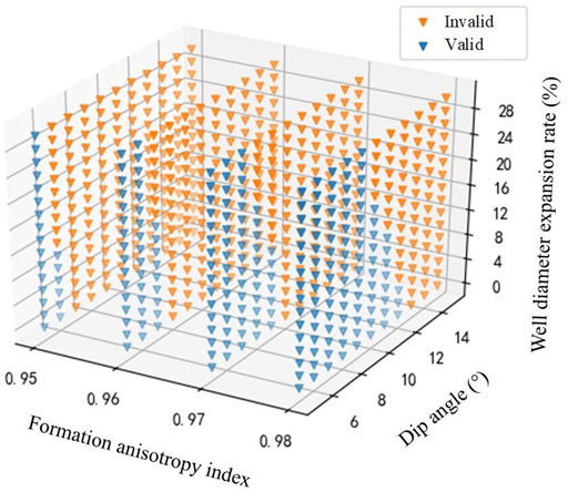
FIGURE 13. Effective anti-deviation distribution of pendulum BHA in uncertain parameter space.
Similarly, based on the results in Section 3.2 and field experience, the best candidate for bent-housing motor BHA is designed as: Φ215.9 mm bit+Φ172 mm bent-housing motor (1.25° bend angle, with Φ215 mm stabilizer) + Φ158.8 mm short drill collar (2 m) + Φ213 mm stabilizer + Φ158 mm drill collar*20. As shown in Figure 14, the effective anti-deviation probability is 12.9% in the orthogonal formation parameters of the 704 group.
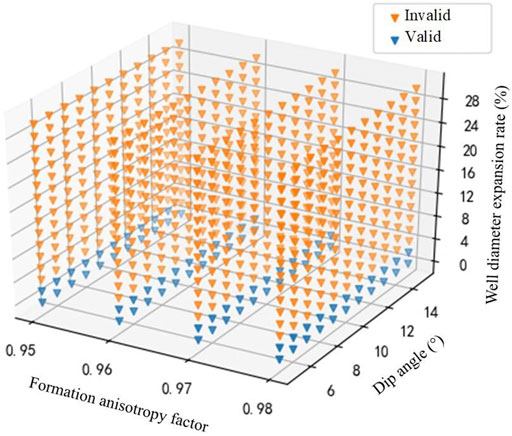
FIGURE 14. Effective anti-deviation distribution of bent-housing motor BHA in uncertain parameter space.
The average ROP is set as 4.83 m/h for both straight-motor pendulum BHA and bent-housing motor BHA, and the ROP is assumed as 1.5 m/h when a small WOB is applied in case of the failure of vertical drilling BHA. The motor cost is 4,000 RMB per day and the rig daily cost is 60,000 RMB per day. The expected cost of the two sets of BHAs is calculated. Assuming that the VDS has 100% anti-deviation success rate, the expected cost of the VDS is calculated according to the ROP of 5 m/h, daily cost of 45,000 RMB per day and footage cost of 430 RMB per meter. The expected drilling cost of three vertical drilling BHA at different drilling footage are shown in Table 1.
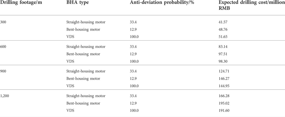
TABLE 1. Expected drilling cost of three vertical drilling BHA.
From Table 1, it can be seen that the straight-housing motor pendulum BHA, with low cost and high anti-deviation probability, is the best choice in the range of 900 m footage. The anti-deviation probability of the bent-housing motor BHA is low and the corresponding expected drilling cost is high due to the expected existence of hole diameter expansion. With the increase of drilling footage, VDS has become the best choice when the footage reaches 1,200 m.
If there is no expected well diameter expansion, the probability calculation is redone. The new calculation results show that the success rate of the pendulum BHA and the bent-housing motor BHA are 36.4% and 100%, respectively. Therefore, it is advisable to use the bent-housing motor BHA in the current situation. At the same time, the importance of hole diameter expansion to the performance of vertical drilling BHA is highlighted.
4 Conclusion
In this paper, a new mechanical model of bent-housing motor BHA is established based on beam-column theory, a build rate prediction method is presented, and a method of designing vertical drilling BHA considering formation uncertainties is proposed. The main factors affecting anti-deviation performance of pendulum BHA and bent-housing motor BHA are analyzed.
The main factors affecting the deviation prevention capability of pendulum BHA are formation dip, formation anisotropy and hole diameter expansion, and the distance between stabilizer and bit, stabilizer diameter and WOB also have certain effects. The main factors affecting the anti-deviation ability of bent-housing motor BHA are formation dip, formation anisotropy, hole diameter expansion and the distance from the upper stabilizer to the bit, while the bend angle and WOB have relatively small influence. The case study of vertical drilling BHA design shows that hole diameter expansion is very important and must be taken into account during the design of BHA.
Data availability statement
The original contributions presented in the study are included in the article/Supplementary Material, further inquiries can be directed to the corresponding author.
Author contributions
CX and WZ establish the mechanical model of BHA, and propose the BHA design method. CX writes the paper. NZ and HC help to provide BHA structure and formation information.
Acknowledgments
The authors thank PetroChina Xinjiang Oilfield Company for the support and the permission to publish this research.
Conflict of interest
Authors CX, WZ, NZ, and HC were employed by the PetroChina Xinjiang Oilfield Company.
Publisher’s note
All claims expressed in this article are solely those of the authors and do not necessarily represent those of their affiliated organizations, or those of the publisher, the editors and the reviewers. Any product that may be evaluated in this article, or claim that may be made by its manufacturer, is not guaranteed or endorsed by the publisher.
References
Bai, J. “Bottom hole assembly problems solved by beam-column theory,” in Proceedings of the Paper presented at the International Petroleum Exhibition and Technical Symposium, Beijing, China, March 1982. SPE-10561. doi:10.2118/10561-MS
Bai, J., Huang, Z., and Liu, Y. (1989). Three-dimensional analysis of bottom hole assembly by beam-column theory. Acta Pet. Sin. 10 (2), 60–66. doi:10.7623/syxb198902008
Bai, J., and Lin, X. (1985). Two-dimensional analysis of bottom hole assembly by beam-column theory. Acta Pet. Sin. 6 (3), 75–84. doi:10.7623/syxb198503010
Greenwood, J., Marck, J., Nair, V. N., and Munguia, J. “Drilling performance evaluation using advanced BHA modeling and field validation,” in Proceedings of the Paper presented at the IADC/SPE International Drilling Conference and Exhibition, Galveston, Texas, USA, March 2020. doi:10.2118/199617-MS
Ho, H. S. “Prediction of drilling trajectory in directional wells via a new rock-bit interaction model,” in Proceedings of the Paper presented at the SPE Annual Technical Conference and Exhibition, Dallas, Texas, September 1987. doi:10.2118/16658-MS
Menand, S., Mills, K. A., and Suarez, R. “Micro dogleg detection with continuous inclination measurements and advanced BHA modeling,” in Proceedings of the Paper presented at the Abu Dhabi International Petroleum Exhibition & Conference, Abu Dhabi, UAE, November 2016. doi:10.2118/184074-MS
Menand, S., Sellami, H., Tijani, M., Stab, O., Dupuis, D., and Simon, C. “Advancements in 3D drillstring mechanics: From the bit to the topdrive,” in Proceedings of the Paper presented at the IADC/SPE Drilling Conference, Miami, Florida, USA, February 2006. SPE-98965. doi:10.2118/98965-MS
Millheim, K., Jordan, S., and Ritter, C. J. (1978). Bottom-hole assembly analysis using the finite-element method. J. Petroleum Technol. 30, 265–274. SPE-6057. doi:10.2118/6057-pa
Neubert, M., Heisig, G., Forstner, I., and Mounzer, F. “Verification of an advanced BHA analysis model with downhole bending moment measurements,” in Proceedings of the Paper presented at the SPE Asia Pacific Oil and Gas Conference and Exhibition, Jakarta, Indonesia, April 2005. SPE-93864. doi:10.2118/93864-MS
Shi, Y., Guan, Z., Zhao, H., and Huang, G. (2017). A new method for build-up rate prediction of bottom-hole assembly in well drilling. J. China Univ. Petroleum Ed. Nat. Sci. 41 (1), 85–89. doi:10.3969/j.issn.1673-5005.2017.01.010
Si, G., Wei, L., Huang, W., Guo, Z., and Chen, Y. (2009). The main influencing factors on the drilling cost and the corresponding controlling measures. Nat. Gas. Ind. 29 (9), 106–109. doi:10.3787/j.issn.1000-0976.2009.09.030
Wang, G., Huang, W., and Gao, D. (2022). Prediction and analysis of build-up rate during sliding drilling. Oil Drill. Prod. Technol. 44 (2), 139–144. doi:10.13639/j.odpt.2022.02.001
Wilson, J. K. “Field validation of a new BHA model and practical case studies in unconventional shale plays, with a framework for automated analysis for operations support,” in Proceedings of the Paper presented at the SPE/AAPG Eastern Regional Meeting, Pittsburgh, Pennsylvania, USA, October 2018. doi:10.2118/191780-18ERM-MS
Wilson, J. K. (2017). Nonlinear drillstring modeling with applications to induced vibrations in unconventional horizontal wells[D]. Dissertation. College Station: Texas A&M University. Available at: https://hdl.handle.net/1969.1/161300.
Keywords: vertical drilling, BHA design, bit-rock interaction, formation dip, formation anisotropy
Citation: Xi C, Zhang W, Zhang N and Chu H (2022) Study on factors affecting vertical drilling bottom hole assembly performance and a new bottom hole assembly design method considering formation uncertainties. Front. Energy Res. 10:1073135. doi: 10.3389/fenrg.2022.1073135
Received: 18 October 2022; Accepted: 31 October 2022;
Published: 10 November 2022.
Edited by:
Xun Zhong, Yangtze University, ChinaReviewed by:
Yandong Yang, Yan’an University, ChinaWei Li, Sinopec Matrix Corporation, China
Peng Wang, China University of Petroleum, Huadong, China
Copyright © 2022 Xi, Zhang, Zhang and Chu. This is an open-access article distributed under the terms of the Creative Commons Attribution License (CC BY). The use, distribution or reproduction in other forums is permitted, provided the original author(s) and the copyright owner(s) are credited and that the original publication in this journal is cited, in accordance with accepted academic practice. No use, distribution or reproduction is permitted which does not comply with these terms.
*Correspondence: Wei Zhang, MjYzNDI5NTA1OUBxcS5jb20=