- 1Department of Electrical and Electronics Engineering, Electrical Vehicle Charging Research Centre, SRM Institute of Science and Technology, Chennai, Tamilnadu, India
- 2Department of Electrical Engineering, Graphic Era (Deemed to be University), Dehradun, India
- 3Wolfson Centre for Magnetics, School of Engineering, Cardiff University, Cardiff, United Kingdom
- 4Electrical Engineering Department, Faculty of Engineering, Aswan University, Aswan, Egypt
Light-emitting diode (LED) lighting applications aided by an electronic power control have become very attractive in the recent years. For LED lighting applications, it is essential to design a converter with single/multi-output for handling multiple loads. As the LED load is more sensitive to the change in input/converter parameters, it is necessary to regulate the current concerning the design specifications. In this paper, several LED topologies are reviewed with a focus on power density, single/multi-load operation, size, and reliability. Several converter topologies are reviewed and compared in terms of power rating, number of semiconductor switches, isolation, and efficiency. Various modulation techniques used for dimming control are described in brief. The salient features of each converter topology are discussed with the power rating and application for which the topology can be preferred. So, the selection of the power factor correction (PFC) and low source side harmonics converter topology is presented. This paper will be helpful to the researchers who are working on the development of LED drivers.
1 Introduction
In the present scenario, energy saving is a global phenomenon due to the global warming effect and depletion of fossil fuels. It is evident from the global study that 30% of the total energy consumption and 60% of the electricity is spent on buildings (Architecture, 2013, Glass for Europe, 2015, snipview, 2015). Among the energy consumed in the building, lighting is the major load, and it is necessary to improve the efficiency of the system to save energy. Light-emitting diode (LED)-based lights pave a solution for the past decades with better efficiency and high luminous intensity. When compared with other conventional lighting schemes, they have their advantages in terms of physical structure and optical and electrical characteristics. The unique features of LED are that 40% of the electricity is transformed to light, the life span is more than 1000000 h, the start time of the LED is in the order of nanoseconds, heat dissipation is less, and it is available in multi-color (Li and Chen, 2012a, Liang and Huang, 2008, Wang, 2017). Due to the development in the field of packing and coating technology, the size and cost of the LED have decreased, which made it be used for various applications, say street lighting, digital boards, sign boards, architectural buildings, and automotive lighting. The efficiency of the various lights is listed in Table 1 (Wang et al., 2017a).
LED is fabricated with a p–n junction diode with a GaAs semiconductor material to produce an infrared light at 905 nm. The color emitted in LED depends upon the energy difference between the conduction and valance band. When LED is excited with the DC source, electrons gain sufficient energy to move from the valance band to the conduction band, and they fall back to the valence band when they lose energy with the emission of photon (Jaschke and Hoffmann, 2016). The characteristics are similar to pn junction diode characteristics, i.e., the device conducts when the applied voltage is more significant than barrier potential (VF). A small variation in VF results in higher variations in forwarding current. Hence, it is necessary to limit the terminal voltage within the rated current. Also, LED voltage is inversely proportional to the temperature. Therefore, if the lamp is allowed to glow for a long time, the temperature will increase, which results in a rapid rise in the LED current. This may result in the burning of LED as heat cannot be dissipated instantly. If the current source is used instead of the voltage source, an increase in temperature results in a voltage drop that will not damage the LED (Steve Winder; Alonso et al., 2012; Almeida et al., 2015a). Hence, it is advisable to use a constant current source to drive LED.
The efficiency of the LED lighting system can be improved by developing the power converter topology with and without galvanic isolation. The converter with a transformer for isolating the source and load is termed an isolated topology, whereas others are termed non-isolated topologies. Various power conversion stages of LED drivers are a two-stage topology which includes two DC–DC converters (Hui et al., 2010a; Arias et al., 2012; Kim et al., 2016), and a single-stage converter topology with a DC–DC converter (Hui et al., 2010b; Khatua et al., 2020; Jiang et al., 2022). In a two-stage power conversion topology, one converter is used to improve the source side grid power factor (PF), and the other regulates the load current as per the illumination requirements. This topology is preferred for the system with multiple strings of LED load and to control the output current independently. The prime disadvantage of the system is its high cost and not much reliability. In the single-stage power conversion, a DC–DC converter is used to maintain the constant load current as per the specifications. This scheme holds good for single load applications but requires a bulky output capacitor which increases the driver’s size. To improve efficiency and reduce cost, several integrated topologies are developed. These topologies improve the source side PF and reduce the total harmonic distortion with a single DC–DC converter by sharing the semiconductor switches and control circuits of the two-stage topology. This results in the reduction of cost and size with high reliability and efficiency (Chiu et al., 2008; Gacio et al., 2011; Zhang et al., 2020).
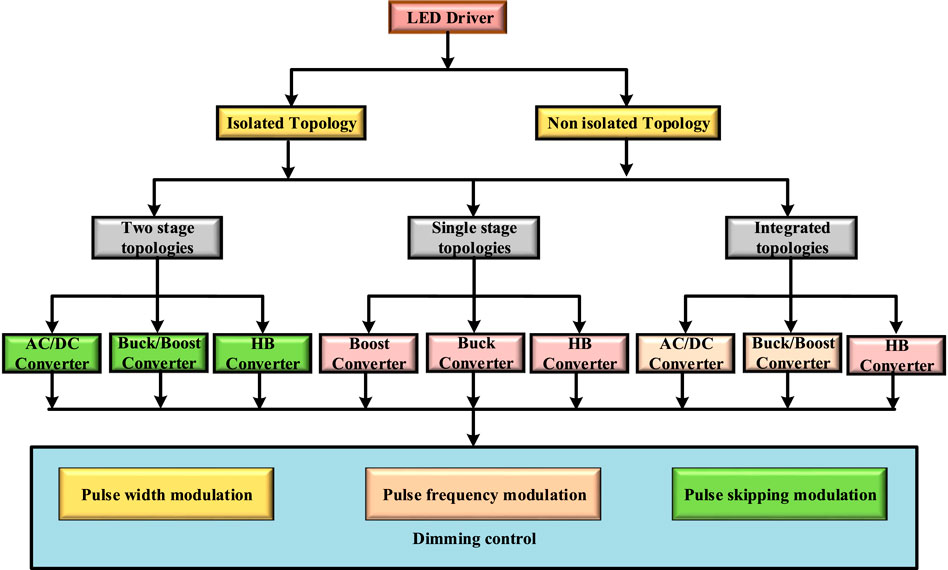
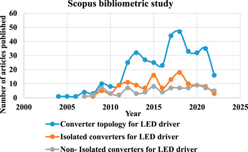
Various modulation techniques used for controlling the output current are pulse frequency modulation (PFM), pulse width modulation (PWM), pulse skipping modulation (PSM), and amplitude modulation (AM) (Hwang et al., 2012), (Kapat and Krein, 2020). These techniques regulate the output current by controlling the inductor current and output voltage when the source voltage is varied. The most commonly used method is the PWM technique, in which the width of the pulses is adjusted to vary the intensity of the light and maintains the output voltage when the source is varied. In the PFM technique, the switching frequency of the converter is varied to regulate the output. In this technique, either on time or off time of the switching frequency is fixed, which in turn, the average value of the inductor current varies to regulate the output. PSM is the constant frequency control which is generally preferred for dimming control. In this technique, the rate of switching used for triggering the converter is controlled by comparing it with the low-frequency signal. In this technique, the peak value of the output current is maintained constant and the average current varies, which in turn, the color of the LED is maintained (Wang et al., 2016a). A general block diagram of the various converter topologies and modulation techniques is illustrated in Figure 1. The fair comparison of the article published in the LED driver is illustrated in Figure 2. A bibliometric study is performed using the keywords “converter topology for LED driver,” “isolated converters for LED driver,” and “non-isolated converters for LED driver,” and it is observed that 376, 129, and 83 are published, respectively.
The course of the paper is organized as follows: Section 2 briefs the antiquity of the light-emitting diode, two-stage converter topologies, and single-stage converter topologies are detailed in Section 3 and Section 4, respectively. Section 5 innumerates the integrated stage converter topologies. The bird’s view is described in brief in Section 6, and Section 7 drafts the conclusion of the paper.
2 Antiquity of light-emitting diode
The evolution of LED eventuated in the early 20th century with Henry Joseph Round, who discovered the study of weak yellow light on a SiC crystal because of the electroluminescence effect in 1907 (Moo et al., 2012), (Round, 1907). The first LED was developed by a Russian scientist Oleg Losev in 1927 and published in various magazines, but it has not been used for real-time applications due to low luminous efficacy (jmargolin). Later in the 1950s, the electroluminescence effect was visualized in a gallium arsenide (GaAs) semiconductor material, and an LED was developed with that effect in the 1960s. It is observed from the experimental study that efficiency is very low at room temperature, and it is able to emit only an invisible infrared light. Hence, it has been decided to replace LED with liquid nitrogen-based lamps (Losev, 1927).
The first practical LED which could emit a visible light was developed by Nick Holonyak 1962, who is an engineer in General Electrical Company (Pilkuhn et al., 1243). This is published in Applied Physics Letters, and he is referred to as the “father of LED” in the newspapers (Holonyak and Bevacqua, 1962). LED technologies started blooming in the 1970s with the invention of red, orange, and green colored light emissions by the American Monsanto Company (Wolinsky, 2005), (Craford et al., 1972). Later, the efficiency of the LED is improved using vapor phase epitaxy technology with gallium arsenide phosphide to have a minimum optical loss in the p–n junction (Duke and Holonyak, 1973). In the middle of the 1970s, gray–green LED was developed by replacing gallium arsenide phosphide with gallium phosphide (GaP). Various LEDs with red, orange, and green colors are developed in the early 1990s with aluminum gallium indium phosphide. In the year 1994, a high illumination blue colored LED was developed using indium gallium nitride by Nichia Company.
The growth of LED started in the 1970s, and it is developing till now with a wide range of the visible spectrum. LED is concentrating more on higher efficiency with improved brightness. In the olden days, LED was used in digital watches and calculators for display, and now it is used everywhere. In recent years, domestic, traffic, and automobile headlights have been replaced with LEDs. Also, various LEDs are commercially developed to meet different standards, which include a power level, flicker emission, applications, and colors. Red–green–blue (RBG) LEDs and organic LEDs (OLEDs) are recently developing technologies to be used in recent research hotspots (Groves et al., 1978), (Hsieh et al., 2009). RGB LEDs were capable of generating different colors instantly, due to which it was used in various applications, say biomedical apparatus (Buso et al., 2014), detector system (Moe et al., 2004), and liquid crystal display (LCD) backlighting (Saucke et al., 2005).
OLEDs are manufactured with semiconductors made up of organic components which have an electroluminescence effect. It consists of two electrodes with an organic semiconductor placed in between. One of the two electrodes is transparent to allow the emission of light. Based on the applied voltage, recombination of electrons and holes takes place in the semiconductor, which emits light. By modifying the molecular structure of the semiconductor, the color of the emitted light can be varied. OLEDs are used in mobile devices due to their lower energy consumption, are mechanically flexible, and thin (Narayanamoorthi and Juliet, 2019)- (Narayanamoorthi et al., 2018). Though they were commercially available, they are high cost with low quality.
Non-isolated converters are preferred for practical applications where compactness, small size, and high efficiency are required. Non-isolated converters are the derived combination of the push–pull, flyback, half-bridge, and full bridge converters with additional modifications. These topologies are selected for small-scale applications which occupy low space. When passive filters are used for PFC in isolated topologies, EMI problem may occur in the LED driver. Hence, a great care needs to be taken while designing such topologies. Various non-isolated topologies are reviewed in this paper.
3 Two-stage converter topologies
A bidirectional and DC–DC two-stage converter for PFC, low-cost, and electrolytic capacitor-less LED driver are proposed, as shown in Figure 3A (Li and Chen, 2012b). The bidirectional converter is used to absorb the second-order harmonics from the input current. The voltage spectrum of the capacitor contains DC and second-order harmonics. Feedforward control is deployed using analog components to regulate the output voltage which is complex in design. This issue is addressed by developing a buck-boost and DC–DC converters with high PF and low THD which are proposed for street lighting applications (Yang et al., 2014). The circuit diagram of the converter is illustrated in Figure 3B. The first DC–DC converter is used to correct the PF and the second buck-boost converter is used to control the LED current. The prototype is verified with 75 W output power for 220 V input voltage which resulted in high current and low voltage at the load side. A high-voltage low-current LED driver is developed for LED applications with a non-electrolytic capacitor (Camponogara et al., 2013) and SiC switch (Wong et al., 2016). The circuit diagram of the high voltage PFC boost converter is illustrated in Figure 3C. The performance of the system in terms of flicker and colorimetric is discussed. The closed-loop control is designed with a third-order harmonic current injection method to reduce the current ripple and flicker with a high power factor. This topology results in more switching losses. An LED AC–DC resonant converter topology is developed for emergency safety lighting applications (Leon-Masich et al., 2016). The circuit diagram of the converter is illustrated in Figure 3D. A current regulator is designed to operate the converter with both ballast and battery. The converter is placed in series with an LED array which acts as the controllable non-dissipative impedance. As the converter is operated in the soft-switching mode, the switching losses are reduced.
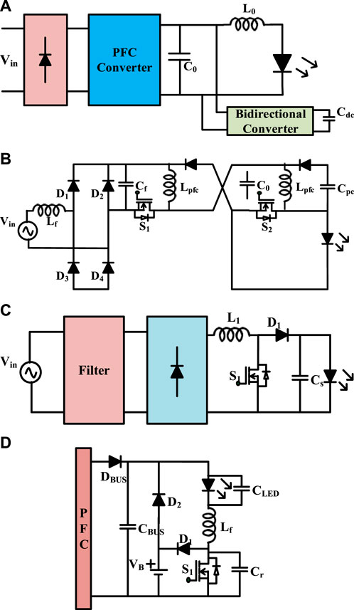
FIGURE 3. (A) Bidirectional and DC–DC converters. (B) Buck-boost DC–DC converter. (C) High-voltage PFC boost converter. (D) AC–DC resonant converter topology.
A low-cost high-efficiency buck converter-based LED driver is developed with dimming control, as shown in Figure 4A (Quintana-Barcia et al., 2022). The converter topology consists of the BJT switch, which is self-oscillating, and current control is deployed with a minimum loss peak current sensing unit. The converter topology is developed with a 24 V DC supply to drive six LEDs. Dimming control is performed using the PWM technique with 93% efficiency. This topology results in a lower power factor when the converter is operated with lesser power. Hence, a high power factor, AC–DC driver with two parallel-connected buck converters is developed, as illustrated in Figure 4B (Chen et al., 2012). One converter improves the source side PF, and the other regulates the current as per the load requirement. Hence, the developed system maintains constant illumination with reduced flickering. The system uses a thin film capacitor which reduces the voltage stress and size of the system. The performance of the system is tested with a 15 W prototype, and the system yields 85.4% efficiency with a 0.94 power and 6.5% current ripple.
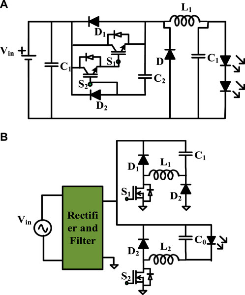
FIGURE 4. (A) High-efficiency buck converter. (B) AC–DC driver with two parallel-connected buck converter.
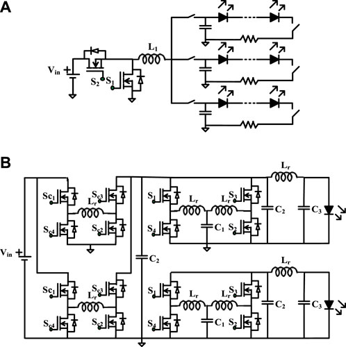
A quasi-two-stage multi-channel multi-output LED driver is proposed with a novel current balancing method (Kim et al., 2017). The load current is limited using the low-power non-isolated DC–DC converter with a series of connected LED strings. The load voltage is maintained constant using the adaptive bus voltage control method. This converter requires more number of components which increases the system cost. Hence, a single-inductor multiple-output LED driver is developed with comprehensive dimming range control (Zhang et al., 2017). The circuit diagram of the converter is illustrated in Figure 5A. Dimming control is performed using the PWM technique in which frequency is increased as per the illumination requirements. A sample and hold circuit is used to reduce the inductor current overshoot during dimming. The control is deployed for constant input voltage. A two-stage multi-load LED driver is proposed for automotive applications, as shown in Figure 5B (Zhang et al., 2020). The developed system has a noninverting front-ended buck-boost converter which allows a wide range of input voltage, and an LCL-T resonant converter to regulate the load current. This topology results in an EMI problem, since passive filter is used for PFC. The efficiency of the system is greater than 88% for a wide range of input voltage variations from 8 to 18 V. Summary of various parameters of two-stage converter topologies fed LED non-isolated drivers is shown in Table 2.
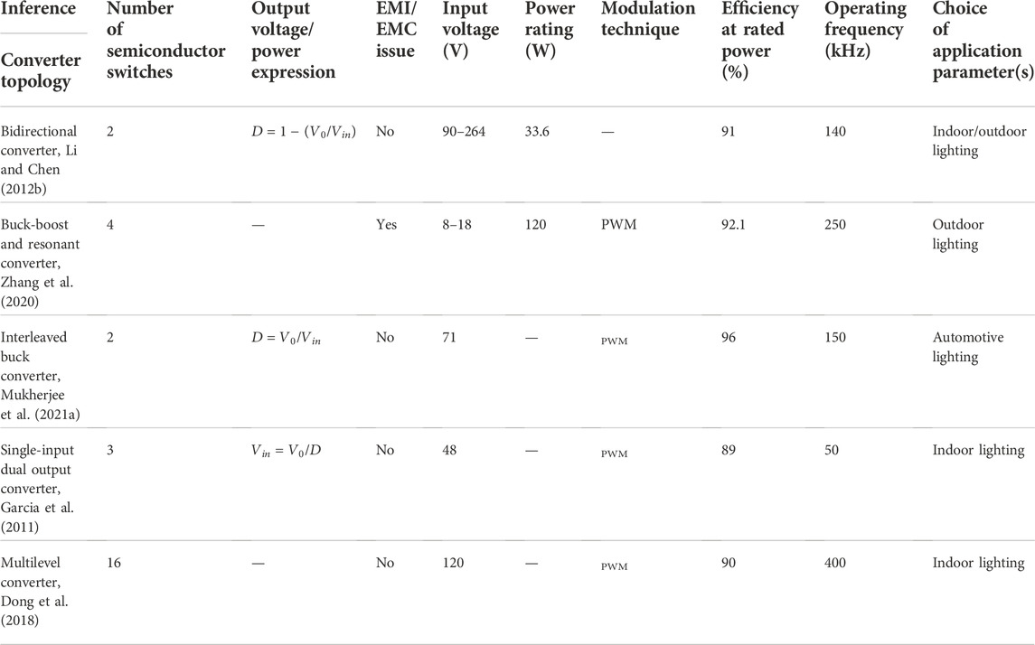
TABLE 2. Summary of various parameters of two-stage converter topologies fed LED non-isolated drivers.
4 Single-stage converter topologies
To reduce the cost and complexity of the system, single-stage topologies fed LED drivers are developed. A 48 V, resonant DC–DC converter with switched capacitor was developed (Gerber et al., 2019). Dimming control is deployed using a variable inductor, as shown in Figure 6A. The effectiveness of the system is validated using the 22 W LED prototype. This driver results in lesser efficiency for lower dimming. A boost LED driver with a snubber circuit is proposed for edge-lit LED backlight applications, as shown in Figure 6B (Martins et al., 2017). The snubber circuit includes an inductor, two diodes, and two capacitors which improved the power conversion efficiency of the system. The maximum efficiency of the system is 94.8% for 24 V input voltage, 114 V output voltage, and 40 W output power. Additional snubber circuit results in more cost and increases the system size. A single switch, the quadratic boost converter, is proposed for the MR16 lighting system as shown in Figure 6C (Lee et al., 2018). PFC is carried out by operating the inductor current in a discontinuous conduction mode. The closed-loop control is deployed using the single switch, which results in cost reduction and improved efficiency. The performance of the system is validated with a 4 W driver.
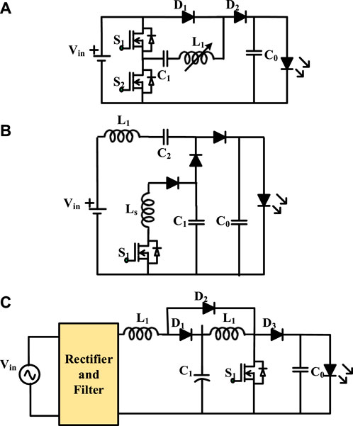
FIGURE 6. (A) DC–DC converter with switched capacitor. (B) Boost LED driver with snubber circuit. (C) Quadratic boost converter for the MR16 lighting system.
A four-switch buck-boost converter is proposed for automotive LED applications, as shown in Figure 7A (Liu et al., 2019). A novel current control is proposed to perform the dimming operation with 0%–100% of the rated power with 1% precision. The prototype is validated with 7–45 V variations in the input voltage. A bulky capacitor used at the output increases the size and cost of the system. A capacitor-less bidirectional DC–DC converter-fed LED driver is proposed for commercial lighting applications (Qin et al., 2017). The bidirectional converter is connected in parallel with the PFC to absorb the second-order harmonics. The converter topology is illustrated in Figure 7B. The output voltage control is performed to maintain the capacitor voltage constant when variations in load occur. The established topology is able to produce only a single output which can feed power to single load. A buck-boost converter with a differential connected switched capacitor is developed (He et al., 2017). The proposed topology uses a multi-output inverting buck-boost converter for mobile applications, as shown in Figure 7C. The developed topology can handle multiple strings of LED with different current ratings, and current balancing control is deployed without an external regulator.
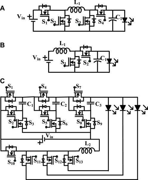
FIGURE 7. (A) 14 four-switch buck-boost converter. (B) Bidirectional DC–DC converter (C) Buck-boost converter with differential connected switched capacitor.
A single-stage boost PFC and charge pump circuit are proposed for high-power applications, as shown in Figure 8 (McRae et al., 2020). The charge pump capacitor help reduces the DC link voltage and improves the source side power factor. It also reduces the flickering of the light as per the IEC 61000-3-2 standards. The topology is validated with input voltage variation from 90 to 270 V, and dimming control is performed at a 127 V and 220 V input voltage. The proposed topology can be operated either in buck or boost mode of operation. A reconfigurable buck-boost converter is proposed for automobile applications with a wide range of input variations (de Araújo et al., 2021). The developed topology integrates the full bridge series resonant inverter and buck-boost converter. An asymmetrical PWM control is used to regulate the output voltage for the variations in an input voltage from 18 V to 120 V. The developed topology is validated with 22.7 W output power and 22.5 V LED with minimum switching losses.
A series resonant and a highly efficient LED driver maintains constant current LED applications (Veeramallu et al., 2021). Frequency control is deployed to maintain the constant illumination for the multi-channel LED driver. The circuit diagram of the HB SRI fed multi-channel LED driver is illustrated in Figure 9A. The performance of the system is validated for six channel LED string with a 50 V output voltage and 0.35 A load current. The variations in the switching frequency results in more switching losses and produced an EMI issue. A novel current control is developed using the phase shift modulation technique for the LCL-T resonant DC–DC converter for a wide range of input variations (Gücin et al., 2019). The converter topology is illustrated in Figure 9B. The converter is operated in a zero voltage switching operation, which minimizes the switching losses. The control is validated in real-time for the variation in input voltage from 3 to 45 V, and the maximum efficiency is obtained as 92.4%. The soft switching is maintained for the narrow range of input variation. A three-switch, dual half-bridge LED with an independent control is developed, as shown in Figure 9C (Mukherjee et al., 2021b). The output current is regulated using an asymmetrical duty cycle control, which results in zero voltage switching for the entire range of input variations. The topology is validated for dual load with 26 and 24 W output power ratings. As multi-loads are used to validate the system, the independent current control is deployed for input voltage variations. A hybrid resonant LED driver with an LCC resonant converter is proposed for automotive LED applications (Kolla et al., 2022). The proposed topology provides the load-independent output current characteristics for the variations in the input voltage. The converter is operated in a continuous conduction mode to boost the input voltage. The analog dimming is performed with 50%–100% of the rated power by adjusting the duty cycle. The prototype is validated with input voltage variations from 8–18 V and 40 W output power rating. Summary of various parameters of single-stage converter topologies fed LED isolated drivers are listed in Table 3.
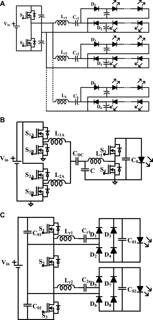
FIGURE 9. (A)HB SRI fed multi-channel LED driver. (B) LCL-T resonant DC–DC converter. (C) Three-switch dual half-bridge LED driver.
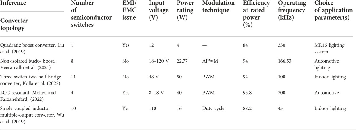
TABLE 3. Summary of various parameters of single-stage converter topologies fed LED isolated drivers.
5 Integrated stage converter topologies
To improve the efficiency of the system, integrated topologies are derived from the two-stage topologies with a single integrated switch. These topologies have minimum switching losses and require a single driver unit. A quasi-resonant buck PFC converter is proposed for LED lighting applications, as shown in Figure 10A (Li, 2015). The output current control is deployed by sensing the current of the converter. The topology results in 0.99 PF with 91.5% efficiency. The performance of the converter is degraded when the switching frequency is varied. A buck converter with a hybrid switching inductor is proposed (Liu et al., 2018). The converter is developed with minimum semiconductor switches, which result in conduction and switching losses, as shown in Figure 10B. The source side power factor is above 0.9, with efficiency greater than 92% for the universal input range. The PF decreases for the increase in input voltage. A high power density offline LED was proposed to be integrated with a buck and boost converter, as shown in Figure 10C (Abdelmessih et al., 2020). The topology results in low THD and better PF with a single controlled switch. The magnetic performance analysis of the converter is carried out for a 46 V input voltage and 0.575 A current. The topology resulted in 92.62% with a 6% output current ripple.
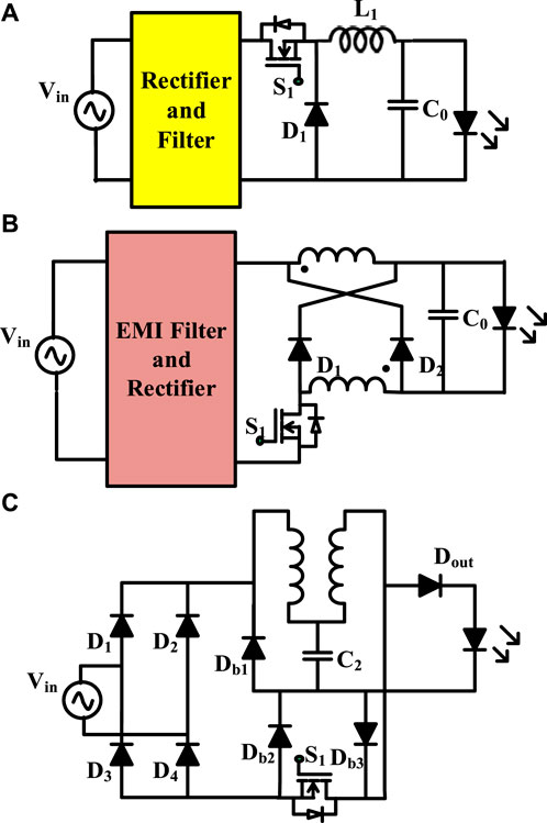
FIGURE 10. (A) Quasi-resonant buck PFC converter; (B) buck converter with hybrid switching inductor; (C) integrated buck and boost converter.
A high step-down resonance-based buck converter is proposed for LED dimming, as shown in Figure 11A (Qu et al., 2011). The converter is operated in discontinuous modes of operation to achieve better PF. The converter switching frequency is selected to reduce the current ripple, which increases the lifetime of the capacitor. This topology can be operated only in a buck mode, which is not preferred for boosting applications. An integrated buck-boost and buck converter is proposed for an LED street light application, as shown in Figure 11B (Gobbato et al., 2018). PFC is carried out using the buck-boost converter, and load current is controlled using the buck converter. The converter is designed in such a manner that the failure in one topology can be compensated using the other. The real topology is validated for a 50 W output power rating, and the current spectrum is compared with IEC61000-3-2 standard. A bulky filter capacitor increases the driver size and cost. An integrated parallel buck-boost and boost converter are proposed for an electrolytic capacitor-less LED driver (Abdelmessih et al., 2022). The circuit diagram is illustrated in Figure 11C. The boost converter cancels the low-frequency ripple, which reduces the flickering, and the buck-boost converter delivers constant power to the load. The system maintains high PF, voltage ripple of 4.5%, and a current ripple of 19% with 92.5% efficiency.
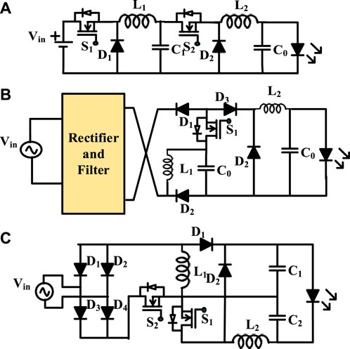
FIGURE 11. (A) High-step-down resonance-based buck converter. (B) Integrated buck-boost and buck converter. (C) Integrated parallel buck-boost and boost converter.
A series resonant DC–DC converter with an integrated bridgeless boost PFC converter is proposed. In the developed driver, the bulk capacitor is replaced with film capacitors which increase the lifetime. The performance of the topology is validated for a100 W output power, and the system yields better efficiency, which is greater than 92%, input PF is greater than 0.97, and current harmonics are maintained as per IEC 61000-3-2 standards. In the developed topology, dimming control is not performed and more number of components are used in the converter. A bridgeless non-resonant boost rectifier-aided HB converter is developed for LED dimming applications (Malschitzky et al., 2018; Malschitzky et al., 2021). The circuit diagram of the bridge’s less HB converter is illustrated in Figure 12. The load current is controlled using a pulse frequency modulation scheme by maintaining the safe operating DC voltage. The developed system results in minimum components with improved PF and EMI. The steady-state and dynamic analysis of the system is carried out for the 42 W prototype of the system. Summary of various parameters of integrated stage converter topologies fed LED isolated drivers are listed in Table 4. Summary of various LED isolated drivers are listed in Table 5.
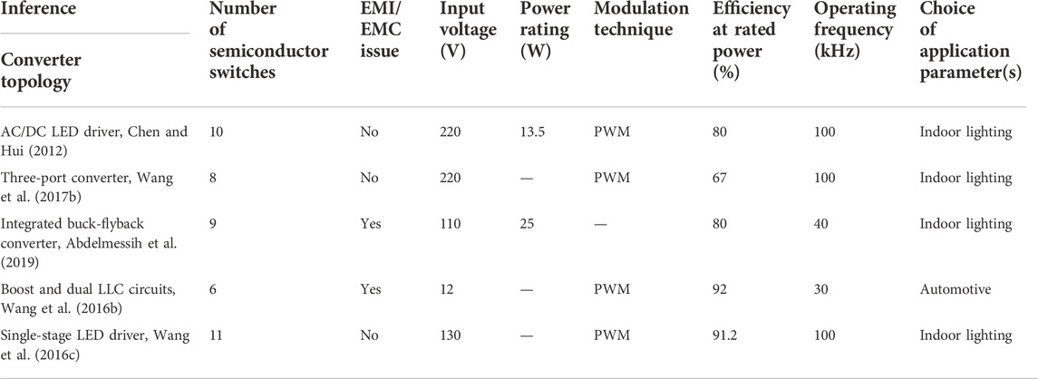
TABLE 4. Summary of various parameters of integrated stage converter topologies fed LED isolated drivers.
6 Bird’s view
From the literature, it is evident that LED lighting scheme plays an important role in several applications, such as indoor, outdoor, automotive, and display. It is the well-enriched technology that includes a power electronic interface as the significant embodiment contains some additional issues to be taken care of to improve the driver performance. Some of the future insights of the system are listed in the following paragraph.
The development of LEDs starts with the growth of semiconductor switches. Thus, a converter design with wide bandwidth semiconductor switches will improve the performance and reliability with maximum efficiency and compact size.
Multi-output load handing-based converter topologies with compact size, minimum thermal distribution, and enhanced performance can be developed. These drivers can be used for indoor and outdoor lighting applications with valuable dimming control. Also, uniform current distribution and independent dimming control with minimum switching losses can be included in the developed topology. While designing the coils, the coupling effect must be accounted for.
Dynamic variation in the source is the key issue in the LED drivers. Hence, a design of a proper controller with minimum time domain specifications is required to have a fast response in the system. Current regulation is the other important task to be addressed during the dimming operation. Hence, an adaptive controller is required for the aforementioned problems.
LED drivers include the PFC unit to improve the PF with minimum harmonics. This results in output power fluctuation, which results in flickering. Therefore, a proper electrolytic capacitor is selected to avoid such issues by maintaining the balanced input and output power. Also, the system should be of compact size with minimum cost.
With the demand in the illumination, color, thermal characteristics, and lifetime OLED-based lighting scheme can be developed. Modeling the OLED lighting is very essential to study the characteristics. LiFi-based technology can be developed to control the lighting scheme.
7 Conclusion
From the extensive review, various isolated and non-isolated converter topologies are reviewed, and the following concluding remarks are made:
1) It is observed from the various literature works that the growth of LED lighting scheme is increased in the recent years. Various research studies are carried out in the development of power converters, various modulation techniques for dimming control, and the selection of light for various applications.
2) A two-stage power conversion topology has two converter topologies in which one is used to correct the PF, and the other regulates the load current. This topology has more number of components and is more complex to control the system. Also, due to more power conversion stages, there are more losses in the system.
3) In a single-stage power conversion scheme, a DC–DC converter is used to correct the PF or regulate the load current. This driver has a simple structure, minimum losses, and is easy to control the load. However, PFC and current regulation is not feasible by the same topology.
4) The integrated topology includes a single converter which is the combination of two DC–DC converters which can help perform PFC and load regulation with the same topology. This topology results in reduced components and minimum losses when compared with other topologies.
5) Isolated converter topologies use a transformer that isolates the load and source. This topology requires an additional transformer which increases the system cost and size. This is overcome with non-isolated topologies, which have the minimum number of components.
6) Various modulation techniques are used to vary the load current to have the dimming control. Among the studied techniques, pulse skipping modulation results in better control.
The research road map for the power electronic converter interface and the modulation techniques used for the LED driver is very clear. This review helps the researchers to identify the appropriate converter for the LED driver.
Author contributions
All authors listed have made a substantial, direct, and intellectual contribution to the work and approved it for publication.
Conflict of interest
The authors declare that the research was conducted in the absence of any commercial or financial relationships that could be construed as a potential conflict of interest.
Publisher’s note
All claims expressed in this article are solely those of the authors and do not necessarily represent those of their affiliated organizations, or those of the publisher, the editors, and the reviewers. Any product that may be evaluated in this article, or claim that may be made by its manufacturer, is not guaranteed or endorsed by the publisher.
References
Abdelmessih, G. Z., Alonso, J. M., Dalla Costa, M. A., Chen, Y. -J., and Tsai, W. -T. (2020). Fully integrated buck and boost converter as a high efficiency, high-power-density off-line LED driver. IEEE Trans. Power Electron. 35 (11), 12238–12251. doi:10.1109/TPEL.2020.2993796
Abdelmessih, G. Z., Alonso, J. M., Spode, N. d. S., and Costa, M. A. D. (2022). High-efficient electrolytic-capacitor-less offline LED driver with reduced power processing. IEEE Trans. Power Electron. 37 (2), 1–1815. doi:10.1109/TPEL.2021.3108137
Abdelmessih, G. Z., Alonso, J. M., and Tsai, W. T. (2019). Analysis and experimentation on a new high power factor off-line LED driver based on interleaved integrated buck flyback converter. IEEE Trans. Ind. Appl. 55 (4), 4359–4369. doi:10.1109/TIA.2019.2910785
Almeida, P. S., Braga, H. A. C., Dalla Costa, M. A., and Alonso, J. M. (2015a). Offline soft-switched LED driver based on an integrated bridgeless boost–asymmetrical half-bridge converter. IEEE Trans. Ind. Appl. 51 (1), 761–769. doi:10.1109/TIA.2014.2332066
Almeida, P. S., Camponogara, D., Dalla Costa, M., Braga, H., and Alonso, J. M. (2015b). Matching LED and driver life spans: A review of different techniques. EEE. Ind. Electron. Mag. 9 (2), 36–47. doi:10.1109/mie.2014.2352861
Alonso, J. M., Vi˜na, J., Vaquero, D. G., Mart´ınez, G., and Osorio, R. (2012). Analysis and design of the integrated double buck–boost converter as a high-powerfactor driver for power-LED lamps. IEEE Trans. Ind. Electron. 59 (4), 1689–1697. doi:10.1109/tie.2011.2109342
Architecture, (2013). Why the building sector?” 2015. [Online]. Available: http://architecture2030.org/buildings_problem_why.
Arias, Manuel, Vazquez, Aitor, and Sebastián, Javier (2012). An overview of the AC-DC and DC-DC converters for LED lighting applications. Automatika 53, 156–172. doi:10.7305/automatika.53-2.154
Buso, D., Bhosle, S., Liu, Y., Ternisien, M., Renaud, C., and Chen, Y. (2014). OLED electrical equivalent device for driver topology design. IEEE Trans. Ind. Appl. 50 (2), 1459–1468. doi:10.1109/tia.2013.2272432
Camponogara, D., Ferreira, G. F., Campos, A., Dalla Costa, M. A., and Garcia, J. (2013). Offline LED driver for street lighting with an optimized cascade structure. IEEE Trans. Ind. Appl. 49 (6), 2437–2443. doi:10.1109/TIA.2013.2263631
Chen, H. T., Choy, W. C. H., and Hui, S. Y. (2016). Characterization, modeling, and analysis of organic light-emitting diodes with different structures. IEEE Trans. Power Electron. 31 (1), 581–592. doi:10.1109/tpel.2015.2403618
Chen, W., and Hui, S. Y. R. (2012). Elimination of an electrolytic capacitor in AC/DC light-emitting diode (LED) driver with high input power factor and constant output current. IEEE Trans. Power Electron. 27 (3), 1598–1607. doi:10.1109/TPEL.2010.2103959
Chen, Y., Nan, Y., and Kong, Q. (2012). A loss-adaptive self-oscillating buck converter for LED driving. IEEE Trans. Power Electron. 27 (10), 4321–4328. doi:10.1109/TPEL.2012.2190755
Chiu, H. J., Song, T. H., Cheng, S. J., Li, C. H., and Lo, Y. K. (2008). Design and implementation of a single-stage high-frequency HID lamp electronic ballast. IEEE Trans. Ind. Electron. 55 (2), 674–683. doi:10.1109/tie.2007.896024
Craford, M. G., Shaw, R. W., Herzog, A. H., and Groves, W. O. (1972). Radiative recombination mechanisms in GaAsP diodes with and without nitrogen doping. J. Appl. Phys. 43, 4075–4083. doi:10.1063/1.1660876
de Araújo, L., Agostini, E., and Nascimento, C. B. (2021). Single-stage converter based on the boost-PFC rectifier employing a current-source charge-pump for power LEDs applications. IEEE Trans. Power Electron. 36 (9), 10571–10583. doi:10.1109/TPEL.2021.3062717
Dong, Z., Tse, C. K., and Hui, S. Y. R. (2018). Current-source-mode single-inductor multiple-output LED driver with single closed-loop control achieving independent dimming function. IEEE J. Emerg. Sel. Top. Power Electron. 6 (3), 1198–1209. doi:10.1109/JESTPE.2018.2831686
Duke, C. B., and Holonyak, J. N. (1973). Advances in light-emitting diodes. Phys. Today 26, 23–31. doi:10.1063/1.3128359
Gacio, D., Alonso, J. M., Calleja, A. J., Garcia, J., and Rico-Secades, M. (2011). A Universal-Input Single-Stag2e High-Power-Factor Power Supply for HB-LEDs Based on Integrated Buck–Flyback Converter. IEEE Trans. Ind. Electron. 58 (2), 589–599. doi:10.1109/tie.2010.2046578
Garcia, J., Calleja, A. J., Corominas, E. L., Vaquero, D. G., and Campa, L. (2011). Interleaved buck converter for fast PWM dimming of high-brightness LEDs. IEEE Trans. Power Electron. 26 (9), 2627–2636. doi:10.1109/TPEL.2011.2121922
Gerber, D. L., Le, C., Kline, M., Kinget, P. R., and Sanders, S. R. (2019). An integrated multilevel converter with sigma–delta control for LED lighting. IEEE Trans. Power Electron. 34 (4), 3030–3040. doi:10.1109/TPEL.2018.2851211
Glass for Europe, (2015). Share of totalEUenergy consumption. [Online]. Available: http://www.glassforeuropea.com/en/issues/faq.php.
Gobbato, C., Kohler, S. V., de Souza, I. H., Denardin, G. W., and Lopes, J. d. P. (2018). Integrated topology of DC–DC converter for LED street lighting system based on modular drivers. IEEE Trans. Ind. Appl. 54 (4), 3881–3889. doi:10.1109/TIA.2018.2808905
Groves, W. O., Herzog, H. A., and Craford, M. G., et al. (1978). GaAsP electroluminescent device doped with isoelectronic impurities. U.S. Pat. 29 845.
Gücin, T. N., Fincan, B., and Biberoğlu, M. (2019). A series resonant converter-based multichannel LED driver with inherent current balancing and dimming capability. IEEE Trans. Power Electron. 34 (3), 2693–2703. doi:10.1109/TPEL.2018.2838261
He, J., Ruan, X., and Zhang, L. (2017). Adaptive voltage control for bidirectional converter in flicker-free electrolytic capacitor-less AC–DC LED driver. IEEE Trans. Ind. Electron. 64 (1), 320–324. doi:10.1109/TIE.2016.2608767
Holonyak, N., and Bevacqua, S. F. (1962). Coherent (visible) light emission from ga(as1−xpx) junctions. Appl. Phys. Lett. 1 (4), 82–83. doi:10.1063/1.1753706
Hsieh, C. Y., Yang, C. Y., and Chen, K. H. (2009). A charge-recycling buck-store and boost-restore (BSBR) technique with dual outputs for RGB LED backlight and flashlight module. IEEE Trans. Power Electron. 24 (8), 1914–1925. doi:10.1109/tpel.2009.2017745
Hui, S. Y. R., Li, S. N., Tao, X. H., Chen, W., and Ng, W. M. (2010a). A novel passive off-line light-emitting diode (LED) driver with long lifetime Presented at applied power electronics conference and exposition (APEC). Palm Springs, CA: Fifth Annual IEEE.
Hui, S. Y., Sinan, L., Tao, X., Chen, W., and Ng, W. M. (2010b). A novel passive offline LED driver with long lifetime. Power electronics. IEEE Trans. 25, 2665–2672. doi:10.1109/TPEL.2010.2048436
Hwang, J. T., Jung, M. S., Kim, D. H., Lee, J. H., Jung, M. H., and Shin, J. H. (2012). Off-the-Line primary side regulation LED lamp driver with single-stage PFC and TRIAC dimming using LED forward voltage and duty variation tracking control. IEEE J. Solid-State Circuits 47 (12), 3081–3094. doi:10.1109/JSSC.2012.2225735
Jaschke, R., and Hoffmann, K. F. (May 2016). “Higher light efficacy in LED-lamps by lower LED-current,” in Proceedings of the PCIM Eur.Int. Exhibi. Conf. Power electron., intell. Motion (Nuremberg Germany: Renewable Energy EnergyManage.), 1–5.
Jiang, W. Z., Hwu, K. I., and Shieh, J. J. (2022). Four-channel buck-type LED driver with automatic current sharing and soft switching. Appl. Sci. 12, 5842. doi:10.3390/app12125842
jmargolin, The road to the transistor. [Online]. Available: http: //www.jmargolin.com.
Kapat, S., and Krein, P. T. (2020). A tutorial and review discussion of modulation, control and tuning of high-performance DC-DC converters based on small-signal and large-signal approaches. IEEE Open J. Power Electron. 1, 339–371. doi:10.1109/OJPEL.2020.3018311
Khatua, M., Kumar, A., Yousefzadeh, V., Sepahvand, A., Doshi, M., Maksimovic, D., et al. (2020). High-performance megahertz-frequency resonant DC-DC converter for automotive LED driver applications. IEEE Trans. Power Electron. 35, 10396–10412. doi:10.1109/TPEL.2020.2974970
Kim, H., Choi, M. C., Kim, S., and Jeong, D. (2017). An AC–DC LED driver with a two-parallel inverted buck topology for reducing the light flicker in lighting applications to low-risk levels. IEEE Trans. Power Electron. 32 (5), 3879–3891. doi:10.1109/TPEL.2016.2582856
Kim, J. W., Moon, J. P., and Moon, G. W. (2016). Analysis and design of a single switch forward-flyback two-channel LED driver with resonant-blocking capacitor. IEEE Trans. Power Electron. 31 (3), 2314–2323. doi:10.1109/tpel.2015.2432458
Kolla, H. R., Vishwanathan, N., and Murthy, B. K. (2022). Independently controllable dual-output half-bridge series resonant converter for LED driver application. IEEE J. Emerg. Sel. Top. Power Electron. 10 (2), 2178–2189. doi:10.1109/JESTPE.2021.3120879
Lee, S. W., Choe, H. J., and Yun, J. J. (2018). Performance improvement of a boost LED driver with high voltage gain for edge-lit LED backlights. IEEE Trans. Circuits Syst. Ii. 65 (4), 481–485. doi:10.1109/TCSII.2017.2716442
Leon-Masich, A., Valderrama-Blavi, H., Bosque-Moncusí, J. M., and Martínez-Salamero, L. (2016). A high-voltage SiC-based boost PFC for LED applications. IEEE Trans. Power Electron. 31 (2), 1633–1642. doi:10.1109/TPEL.2015.2418212
Li, H. Y., and Chen, H. C. (2012a). Dynamic modeling and controller design for a single-stage single-switch parallel boost-flyback–flyback converter. IEEE Trans. Power Electron. 27 (2), 816–827. doi:10.1109/tpel.2010.2098049
Li, Y. C. (2015). A novel control scheme of quasi-resonant valley-switching for high-power-factor AC-to-DC LED drivers. IEEE Trans. Ind. Electron. 62 (8), 4787–4794. doi:10.1109/TIE.2015.2397875
Li, Y., and Chen, C. (2012b). A novel single-stage high-power-factor AC-to-DC LED driving circuit with leakage inductance energy recycling. IEEE Trans. Ind. Electron. 59 (2), 793–802. doi:10.1109/TIE.2011.2151817
Liang, T. J., and Huang, C. M. (2008). Interleaving controlled three-leg electronic ballast for Dual-HID-Lamps. IEEE Trans. Power Electron. 23 (3), 1401–1409. doi:10.1109/tpel.2008.921182
Liu, X., Li, X., Zhou, Q., and Xu, J. (2019). Flicker-free single-switch quadratic boost LED driver compatible with electronic transformers. IEEE Trans. Ind. Electron. 66 (5), 3458–3467. doi:10.1109/TIE.2018.2851985
Liu, Y. -C., Syu, F. -C., Hsieh, H. C., Kim, K. A., and Chiu, H. -J. (2018). Hybrid switched-inductor buck PFC converter for high-efficiency LED drivers. IEEE Trans. Circuits Syst. Ii. 65 (8), 1069–1073. doi:10.1109/TCSII.2017.2787554
Losev, O. V. (1927). Luminous carborundum [[silicon carbide]] detector and detection with crystals. Telegr. i Telef. bez Provodov 19, 485–494.
Malschitzky, A., Agostini, E., and Nascimento, C. B. (2021). Integrated bridgeless-boost nonresonant half-bridge converter employing hybrid modulation strategy for LED driver applications. IEEE Trans. Ind. Electron. 68 (9), 8049–8060. doi:10.1109/TIE.2020.3013749
Malschitzky, A., Albuquerque, F., Agostini, E., and Nascimento, C. B. (2018). Single-stage integrated bridgeless-boost nonresonant half-bridge converter for LED driver applications. IEEE Trans. Ind. Electron. 65 (5), 3866–3878. doi:10.1109/TIE.2017.2760842
Martins, M., Perdigão, M. S., Mendes, A. M. S., Pinto, R. A., and Alonso, J. M. (2017). Analysis, design, and experimentation of a dimmable resonant-switched-capacitor LED driver with variable inductor control. IEEE Trans. Power Electron. 32 (4), 3051–3062. doi:10.1109/TPEL.2016.2575918
McRae, T., Prodić, A., Chakraborty, S., McIntyre, W., and Aguilar, A. (2020). A hybrid multioutput divided power converter for LED applications. IEEE J. Emerg. Sel. Top. Power Electron. 8 (3), 2041–2055. doi:10.1109/JESTPE.2019.2954299
Moe, A. E., Banani, N., Lee, L. A., Marquardt, B., and Wilson, D. M. (2004). Enhanced fluorescence emission using a programmable, reconfigurable LED-array based light source. Conf. Proc. IEEE Eng. Med. Biol. Soc. 3, 2090–2093. doi:10.1109/IEMBS.2004.1403614
Molavi, N., and Farzanehfard, H. (2022). Load-independent hybrid resonant converter for automotive LED driver applications. IEEE Trans. Power Electron. 37 (7), 8199–8206. doi:10.1109/TPEL.2022.3144640
Moo, C. S., Chen, Y. J., and Yang, W. C. (2012). An efficient driver for dimmable LED lighting. IEEE Trans. Power Electron. 27 (11), 4613–4618. doi:10.1109/TPEL.2012.2183892
Mukherjee, S., Yousefzadeh, V., Sepahvand, A., Doshi, M., and Maksimović, D. (2021a). A two-stage automotive LED driver with multiple outputs. IEEE Trans. Power Electron. 36 (12), 14175–14186. doi:10.1109/TPEL.2021.3077528
Mukherjee, S., Yousefzadeh, V., Sepahvand, A., Doshi, M., and Maksimović, D. (2021b). High-frequency wide-range resonant converter operating as an automotive LED driver. IEEE J. Emerg. Sel. Top. Power Electron. 9 (5), 5781–5794. doi:10.1109/JESTPE.2020.3025016
Narayanamoorthi, R., and Juliet, A. V. (2019). Capacitor-less high-strength resonant wireless power transfer using open bifilar spiral coil. IEEE Trans. Appl. Supercond. 29 (1), 15500108–8. doi:10.1109/TASC.2018.2848268
Narayanamoorthi, R., Juliet, V., Padmanaban, S., Mihet-Popa, L., and Bharatiraja, C. (2018). Frequency splitting elimination and cross-coupling rejection of wireless power transfer to multiple dynamic receivers. Appl. Sci. 8 (2), 179. doi:10.3390/app8020179
Pilkuhn, M., Rupprecht, H., and Woodall, J. (1963). Continuous stimulated emission fromGaAs diodes at 77K. Proc. IEEE 51 (9), 1243. doi:10.1109/proc.1963.2505
Qin, Y., Li, S., and Hui, S. Y. (2017). Topology-transition control for wide-input-voltage-range efficiency improvement and fast current regulation in automotive LED applications. IEEE Trans. Ind. Electron. 64 (7), 5883–5893. doi:10.1109/TIE.2017.2686304
Qu, X., Wong, S. C., and Tse, C. K. (2011). Resonance-assisted buck converter for offline driving of power LED replacement lamps. IEEE Trans. Power Electron. 26 (2), 532–540. doi:10.1109/TPEL.2010.2065242
Quintana-Barcia, P., Ribas, J., Juarez-Leon, F. A., and Rodriguez-Fuertes, D. (2022). Permanent emergency LED lamp based on a series single-switch resonant converter with battery clamp. IEEE Trans. Ind. Electron. 69 (10), 9992–10000. doi:10.1109/TIE.2021.3123649
Saucke, K., Pausch, G., Stein, J., Ortlepp, H.-G., and Schotanus, P. (2005). Stabilizing scintillation detector systems with pulsed LEDs: A method to derive the LED temperature from pulse height spectra. IEEE Trans. Nucl. Sci. 52 (6), 3160–3165. doi:10.1109/tns.2005.862929
snipview, (2015). Energy in China. [Online]. Available: http://www.snipview.com/q/Energy%20in%20Chi.
Veeramallu, V. K. S., Porpandiselvi, S., and Narasimharaju, B. L. (2021). A nonisolated wide input series resonant converter for automotive LED lighting system. IEEE Trans. Power Electron. 36 (5), 5686–5699. doi:10.1109/TPEL.2020.3032159
Wang, Y., Li, P., and Lai, S. (2016a). Robust and efficient transistor-level envelope-following analysis of PWM/PFM/PSM DC-DC converters. IEEE Trans. Comput. -Aided. Des. Integr. Circuits Syst. 35 (11), 1836–1847. doi:10.1109/TCAD.2016.2524565
Wang, Y., Gao, S., Guan, Y., Huang, J., Xu, D., and Wang, W. (2016b). A single-stage LED driver based on double LLC resonant tanks for automobile headlight with digital control. IEEE Trans. Transp. Electrific. 2 (3), 357–368. doi:10.1109/TTE.2016.2571781
Wang, Y., Huang, J., Shi, G., Wang, W., and Xu, D. (2016c). A single-stage single-switch LED driver based on the integrated SEPIC circuit and class-E converter. IEEE Trans. Power Electron. 31 (8), 5814–5824. doi:10.1109/TPEL.2015.2489464
Wang, Y. (2017). A review of led drivers and related technologies. Trans. Industrial Electron., 1. doi:10.1109/TIE.2017.2677335
Wang, F., Li, L., Zhong, Y., and Shu, X. (2017b). Flyback-based three-port topologies for electrolytic capacitor-less LED drivers. IEEE Trans. Ind. Electron. 64 (7), 5818–5827. doi:10.1109/TIE.2017.2677303
Wong, C. S., Loo, K. H., Lai, Y. M., Chow, M. H. L., and Tse, C. K. (2016). An alternative approach to LED driver design based on high-voltage driving. IEEE Trans. Power Electron. 31 (3), 2465–2475. doi:10.1109/TPEL.2015.2434496
Wu, H., Wong, S. C., and Tse, C. K. (2019). A more efficient PFC single-coupled-inductor multiple-output electrolytic capacitor-less LED driver with energy-flow-path optimization. IEEE Trans. Power Electron. 34 (9), 9052–9066. doi:10.1109/TPEL.2018.2886353
Yang, Y., Ruan, X., Zhang, L., He, J., and Ye, Z. (2014). Feed-Forward scheme for an electrolytic capacitor-less AC/DC LED driver to reduce output current ripple. IEEE Trans. Power Electron. 29 (10), 5508–5517. doi:10.1109/TPEL.2013.2293353
Zhang, J., Jiang, T., and Wu, X. (2017). A high-efficiency quasi-two-stage LED driver with multichannel outputs. IEEE Trans. Ind. Electron. 64 (7), 5875–5882. doi:10.1109/TIE.2017.2677310
Zhang, Yimeng, Rong, Guangjian, Qu, Shasha, Cai, ww, Tang, Xiaoyang, and Zhang, Yuming (2020). A high-power LED driver based on single inductor multiple output DC-DC converter with high dimming frequency and wide dimming range. IEEE Trans. Power Electron. 35, 8501–8511. doi:10.1109/TPEL.2020.2971207
Keywords: light-emitting diode, power factor correction, isolated converters, non-isolated converters, single-stage power converter, two-stage power converter, integrated power topology
Citation: Vishnuram P, Narayanamoorthi R, Vijayakumar K, Bajaj M, Shouran M, Abdul Samad B and Kamel S (2022) A comprehensive review on various non-isolated power converter topologies for a light-emitting diode driver. Front. Energy Res. 10:1055258. doi: 10.3389/fenrg.2022.1055258
Received: 27 September 2022; Accepted: 31 October 2022;
Published: 16 November 2022.
Edited by:
Manickam Minakshi, Murdoch University, AustraliaReviewed by:
Shiqi Jiang, Harbin Institute of Technology, ChinaMohamed Salem, Universiti Sains Malaysia (USM), Malaysia
Copyright © 2022 Vishnuram, Narayanamoorthi, Vijayakumar, Bajaj, Shouran, Abdul Samad and Kamel. This is an open-access article distributed under the terms of the Creative Commons Attribution License (CC BY). The use, distribution or reproduction in other forums is permitted, provided the original author(s) and the copyright owner(s) are credited and that the original publication in this journal is cited, in accordance with accepted academic practice. No use, distribution or reproduction is permitted which does not comply with these terms.
*Correspondence: Bdereddin Abdul Samad, YWJkdWxzYW1hZGJmQGNhcmRpZmYuYWMudWs=
 Pradeep Vishnuram
 R. Narayanamoorthi
 K. Vijayakumar
 Mohit Bajaj
 Mokhtar Shouran
 Bdereddin Abdul Samad
 Salah Kamel
