 Ruixue Li
 Hucheng Deng1,3*
 Meiyan Fu
94% of researchers rate our articles as excellent or good
Learn more about the work of our research integrity team to safeguard the quality of each article we publish.
Find out more
ORIGINAL RESEARCH article
Front. Energy Res. , 10 January 2023
Sec. Advanced Clean Fuel Technologies
Volume 10 - 2022 | https://doi.org/10.3389/fenrg.2022.1043231
This article is part of the Research Topic Advanced Methods of Mathematical Modeling and Experimental Study in Oil and Gas Reservoirs View all 15 articles
Carbonate reservoirs usually have a strong heterogeneity. The zones with relatively high permeability will form a channel through which fluids can easily flow. These channels are called thief zones. Thief zones have notable effects on oil or gas production, for example, high oil recovery rates at the early stage of the exploitation or an early water breakthrough during the later stage of water flooding development. Therefore, it is essential to have a precise identification of thief zones in carbonate reservoirs. In this research study, a simple approach to identify thief zones based on reservoir permeability gathered from well logging is developed. The thief zones are first identified at wells based on the lower limit value of the thief-zone permeability. This value is determined based on the dynamic production data, indicating that the thief zones identified by applying this criterion can reflect the product characteristics. Then, a zonal inter-well recognition method is adopted to identify the connectivity and distributions of thief zones in the regions far away from the well. This method is applied to identify thief zones for the Cretaceous Mishrif Formation in the H oilfield, Iraq. The reliability of the identification results is tested by the well-group injection test. The distributions of thief zones in the study region are discussed. In the study region, 12 members developed thief zones, while two members (i.e., MC1-3 and MC2-2) did not develop thief zones. Specifically, there are five members having a high level of thief-zone development. They are MB1-2C, MB2-1, MB2-2, MC2-3, and MC3-2. Comparing the distribution of thief zones with that of sedimentary microfacies, it is concluded that the thief-zone development is mainly controlled by the sedimentary microfacies and tends to occur in high-energy shoals.
Carbonate reservoirs play an essential role in oil and gas recovery, especially in the Middle East and Middle Asia (Liu et al., 2016). Generally, there is a strong heterogeneity in carbonate reservoirs due to the comprehensive impacts of tectonic movement and the leaching effect (Ghafoori et al., 2009; He et al., 2014; Al-Ali et al., 2019). During oil and gas recovery, the zones with relatively high permeability will form low-resistivity seepage channels of fluids, that is, the so-called thief zones (Fu et al., 2019). Thief zones will have high oil recovery rates at the early stage of the exploitation, while they will result in an early water breakthrough and, thereby, lead to a low sweep efficiency at the later stage of water flooding development (Li et al., 2015; Kong et al., 2021). Therefore, it is crucial to identify the thief zones in carbonate reservoirs.
Many methods have been developed to identify thief zones based on analysis of various kinds of data gathered from oilfields, such as core data, well logging data, tracer test data, and production data. The core data (such as permeability, porosity, and pore throat size distribution) can be used to establish the pore structures, therefore providing the basis for the thief-zone identification (He and Hua., 1998; Liao et al., 2001; He et al., 2002). The tracer tests provide an intuitive way of the flow directions. Several researchers analyzed tracer test data to identify the thief zone and obtained relatively precise identification results (Batycky et al., 2008; Izgec and Kabir, 2009; Wang et al., 2011). However, these two methods are both expensive and lack adequate field data. Moreover, the tracer test is time-consuming.
Compared with the core and tracer test data, the well logging and production data are more abundant and can be easily obtained. Therefore, many methods have been developed based on well logging data and production data. Wang et al. (2002) identified thief zones by applying water-injection profile logging data. Al-Dhafeeri and Nasr-El-Din. (2007) adopted both the core data and production logging data to identify thief zones. Li et al. (2008) identified thief zones by using a method combining the high-resolution image logging data with the data collected from the production logging test (PLT) and nuclear magnetic resonance (NMR). Chen et al. (2008) applied the data gathered from PLTs to identify thief zones and provided the distributions of different thief-zone types. Feng et al. (2010) quantitatively identified thief zones between wells using the well test method. John et al. (2013) developed a thief-zone identification method which is a comprehensive analysis of the results obtained by distributed temperature sensing (DTS) technology, PLTs, and water flow logging (WFL). Wei et al. (2019) proposed an index to describe the relative contribution of a certain layer based on the data gathered from PLT. One disadvantage of this kind of method is that the data collected from well logging can only describe the thief zones near well regions (Fu et al., 2019).
In this research study, a simple approach to identify thief zones based on the reservoir permeability obtained from well logging is provided. The lower limit values of the thief-zone permeability in each member are determined based on the dynamic production data. This indicates that the thief zones identified by applying this criterion can reflect the production characteristics. In this identification method, the lower limit values of the thief-zone permeability are first applied to the identified thief zones at each single well. Then, a zonal inter-well recognition method is adopted to carefully capture the connectivity and distributions of thief zones in the regions far away from the well. This identification approach is adopted to identify thief zones for the Cretaceous Mishrif Formation in the H oilfield, Iraq. The reliability of this approach is tested based on a well-group injection test. The distributions of thief zones for the Cretaceous Mishrif Formation in the H oilfield are discussed in this study.
Figure 1 shows the geographical location of the H oilfield. As shown in Figure 1, the H oilfield is approximately 400 km southeast of Baghdad, located in Maysan province in southeastern Iraq. This oilfield is in the foredeep belt of the Mesopotamian basin (Fouad, 2010; Fouad and Sissakian, 2011), which is a wide and gentle anticline with a length and width of about 31 km and 10 km, respectively. The long axis of this anticline is in the NW-SE trending. The H oilfield is a supergiant oilfield. In this oilfield, over 80% of the oil is produced from the limestone of the Lower Cretaceous Sadi Formation and Middle Cretaceous Mishrif Formation. The Mishrif Formation is the most important production zone in the study region with a thickness of around 400 m.
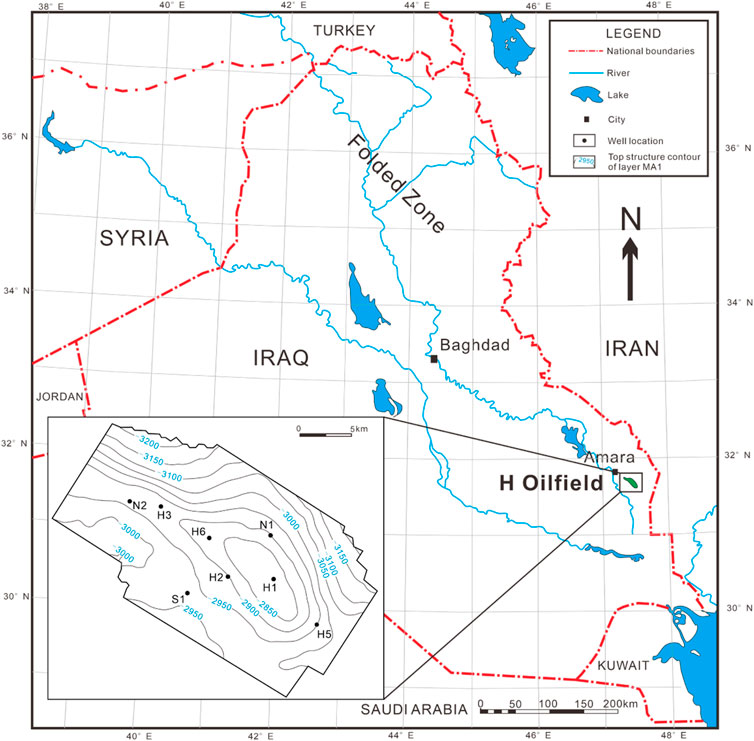
FIGURE 1. Geographical location of the H oilfield (after Fouad, 2015).
Figure 2 shows the stratigraphic column of Cretaceous in the H oilfield. Shelf carbonate developed in the H oilfield (Aqrawi et al., 1998; Wang et al., 2016). The sedimentary facies developing in most areas is an open platform, while a few areas developed the restricted platform and platform edge (Aqrawi et al., 1998; Wang et al., 2016). Based on the different sedimentary hydrodynamic conditions, the sedimentary microfacies in the study region can be divided into high-energy shoals (such as mussel clastic shoal, algal mound, and intraclastic shoal), low-energy shoals (such as bioclastic shoal and shallow open sea), non-clastic facies (such as subtidal flats and marsh), and tidal channels (Zhang et al., 2021). The Mishrif Formation belongs to the Middle Cretaceous deposit. A regional unconformity forms the top of the Mishrif Formation (Wang et al., 2016; Bromhead et al., 2022). The Mishrif Formation in the H oilfield can be further subdivided into 18 members based on the characteristics of lithological variation. The members from top to bottom are MA1, MA2, MB1-1, MB1-2A, MB1-2B, MB1-2C, MB2-1, MB2-2, MB2-3, MC1-1, MC1-2, MC1-3, MC1-4, MC2-1, MC2-2, MC2-3, MC3-1, and MC3-2 (Wang, 2016). Among these members, MA1, MB1-1, MC2-1, and MC3-1 are interlayers.
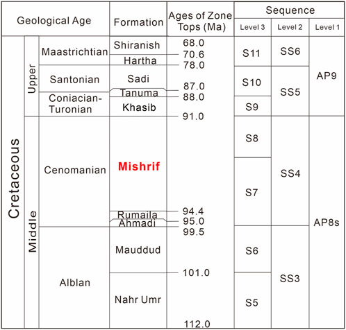
FIGURE 2. Stratigraphic column of Cretaceous in the H oilfield (after Simmons et al., 2007; Wang, 2016; Nasser, 2018; Al-Mimar et al., 2018; Zhang et al., 2021).
The high reservoir heterogeneity of the Mishrif Formation in the H oilfield is usually caused by the comprehensive influence of the sedimentary environment, diagenesis, tectonics, etc. (Ghafoori et al., 2009; He et al., 2014; Al-Ali et al., 2019). There are various lithofacies (with different particle types, particle contents, pore structures, and physical properties) that develop when sedimentary environments change. Sometimes, the diagenesis leads to the dissolution of unstable minerals, which increases the limestone permeability. Figure 3 shows the planar distributions of the intermediate permeability variation coefficients of MB2-2. The permeability variation coefficients (Vk) can be calculated using the following equation.
where Ki and
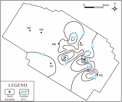
FIGURE 3. Planar distributions of the intermediate permeability variation coefficients of MB2-2.
The strong heterogeneity may cause the oil or the injected water to mainly flow through the zones with high permeability and, thereby, form thief zones. The existence of thief zones will lead to notable contradictions in the production data. Figure 4 shows the distribution of liquid products with the change in the cumulative thickness of the tested zones. It is to be noted that a tested zone usually corresponds to a perforated interval. In this figure, the flow profiles of 86 zones gathered from 14 tested wells are counted. Then, these data are ranked from the smallest to the largest based on their liquid production yield per meter. We defined that the zone with low liquid production is the zone whose liquid production yield per meter is smaller than the average liquid production yield per meter of all tested zones, while the zone with high liquid production is the zone whose liquid production yield per meter is larger than the average value. As shown in Figure 4, it can be found that the zones with low liquid production, whose cumulative thickness occupies 85.8% of the total thickness, only contribute 30.7% of the total liquid production. While the zones with high liquid production, whose cumulative thickness is only 14.2% of the total thickness, contribute 69.3% of the total liquid production. This indicates that thief zones exist in the study region and have a notable effect on oil production, making it necessary to identify thief zones in this region.
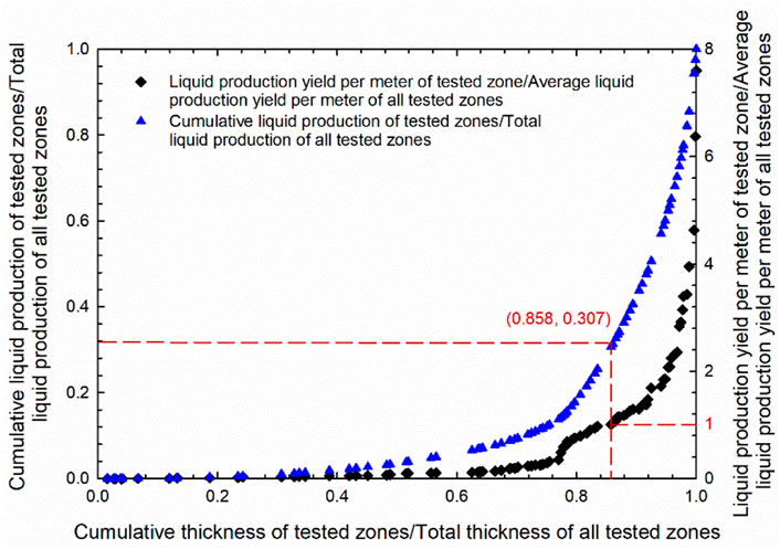
FIGURE 4. Distribution of liquid production with the change of the cumulative thickness of the tested zones (number of tested zones = 86).
Static permeability, which can be easily obtained from well logging, is applied to identify thief zones in this study. The determination of the lower limit values of thief-zone permeability is based on the change of the oil productions of different perforated intervals. Since most wells in our study region have several perforated intervals, the production data collected from these wells are usually the total oil produced from all the perforated intervals. Hence, the layering production split should be first adopted to calculate the oil production from a single perforated interval. In our study region, there are 104 wells with conventional logs, including six cored wells. The permeability data used in this study have been corrected based on core data. The production dynamic data are available for 58 wells, while the PLT data are available for 13 wells.
In this study, the production capacity of a given well is depicted by the average monthly oil production yield per meter. The formation coefficient method (KH method) (Zhao et al., 2010; Zheng et al., 2011) is applied in this study. The KH method is one of the most used production split methods in the oilfield. In this method, the oil production can be split only based on the reservoir permeability and effective thickness. First, the production split coefficient is calculated using the following equation (Zhao et al., 2010; Zheng, et al., 2011):
where Mi represents the production split coefficient used in the KH method; m represents the number of layers; Hi and Hj represent the effective thickness of the ith layer and jth layer, respectively;
where qo and qoi represent the average monthly oil production yield per meter of a well and the ith layer, respectively. As can be seen in Eqs 2, 3, in the KH method, the oil production is split only based on the reservoir permeability and effective thickness. However, the fluid flow in the reservoir is influenced by many factors (such as permeability, relative permeability, fluid phase, pressure, and wettability). If permeability is the main controlling factor of fluid flow in our study region, the KH method canbe applied in this region to roughly predict the oil production from a single layer. Therefore, to test if the KH method can be used to roughly predict the oil production from a single layer in our study region, we compared the calculated production split results with the data obtained by PLT for 13 wells. The detailed comparison results are shown by Li et al. (2021). The maximum, minimum, and average correlation coefficients for these 13 wells are 0.98, 0.60, and 0.80, respectively. This indicates that these two sets of data have a good agreement, indicating that the KH method is applicable in our study region.
It is a prerequisite to know the lower limit values of thief-zone permeability in order to identify thief zones based on the reservoir permeability. Since there is a large discrepancy among the average permeability values of different members, the lower limit values of thief-zone permeability in each member should be different. In this study, different lower limit values of thief-zone permeability are provided for different members, which are determined based on the average permeability values of the corresponding members. Figure 5 shows the variations of the average monthly oil production yield per meter of each perforated interval with the change of the average permeability of the corresponding perforated interval (Kp_aver) dividing the average permeability of all the perforated intervals (Kt_aver). It is to be noted that the average monthly oil production yield per meter of each perforated interval is calculated by the KH method as previously mentioned. This parameter represents the oil production capability of each interval, while Kp_aver/Kt_aver represents the permeability heterogeneity among different intervals. The static and dynamic data gathered from 13 wells in the H oilfield are adopted to generate this figure. As can be seen in Figure 5, in low-permeability intervals (Kp_aver/Kt_aver < 0.8), the permeability controls the oil production capacity. Therefore, the oil production increases as Kp_aver/Kt_aver increases. As permeability increases (0.8 ≤ Kp_aver/Kt_aver ≤2.8), oil can easily pass through the reservoir, thereby leading to a reduced influence of permeability on oil production capacity. In this region, the oil production does not have an obvious increasing tendency as Kp_aver/Kt_aver increases. However, when Kp_aver/Kt_aver <2.8, the permeability again controls the oil production, resulting in a rapid increase in the oil production as the value of Kp_aver/Kt_aver increases. Based on the relationship between the oil production capacity of an interval and permeability heterogeneity among different intervals, the lower limit value of the thief-zone permeability is defined as 2.8 times the average permeability of its corresponding member. Table 1 lists the lower limit values of the thief-zone permeability of 14 members in the Mishrif Formation (except the four interlayers).
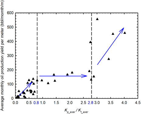
FIGURE 5. Variations of the average monthly oil production yield per meter of each perforated interval with the change of Kp_aver/Kt_aver.
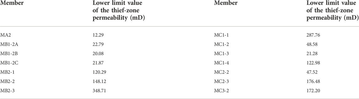
TABLE 1. Lower limit values of the thief-zone permeability of 14 members in the Mishrif Formation (except the four interlayers).
The identification of thief zones can be divided into three procedures. First, based on the lower limit values of the thief-zone permeability of the 14 members, the true vertical depth (TVD) and thickness of thief zones in all the 14 members can be recognized at a given well based on the well logging data. In this research study, thief zones are identified at 104 wells in the H oilfield. Second, TVDs and the thickness of thief zones among neighboring wells are compared to determine the connectivity of thief zones. Lastly, the planar distributions of thief zones in each member can be generated. Since there may be several disconnected thief zones with different TVDs at a well in the same member, it is required to divide a member into several units with different TVDs. The planner distributions of thief zones should be separately generated for each thief-zone unit.
The member MB1-2C is taken as an example to show the detailed method of determining the TVDs of each thief-zone unit. First, we obtained the largest number of thief zones among all 104 wells, which is three. Figure 6 shows the schematic diagram of determining the thickness of thief-zone units in MB1-2C at the well which has the largest number of thief zones (named Well 1). As shown in Figure 6, the zone between two thief zones is evenly divided into two parts, which separately belong to two neighboring thief-zone units. The thief-zone units in a member are numbered from top to bottom. For other wells, the thickness of the three thief-zone units will be the total thickness of MB1-2C multiplied by the proportions of the thickness of the three thief-zone units at Well 1.
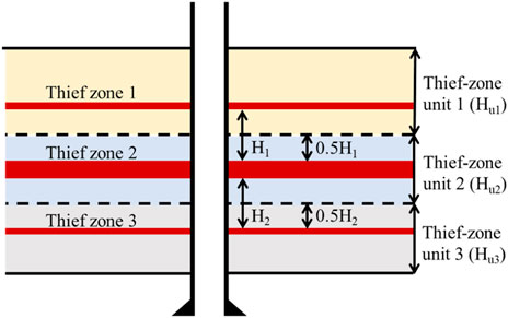
FIGURE 6. Schematic diagram of determining the thickness of thief-zone units in a member at Well 1.
Figure 7 shows the planar distributions of thief zones in MB1-2C. As shown in Figure 7, there are overlaps of the thief zones in different thief-zone units at the same well location. Therefore, it is necessary to divide the member into several thief-zone units in order to clearly characterize the planar distributions of thief zones. Figure 7 mainly describes the large-scale thief zones, which cover three or more wells. The thief zones which cover less than three wells, that is, the small-scale thief zones or thief zones without enough wells to determine their boundaries, are marked with red points and their thickness at each well instead of providing their boundaries. The small-scale thief zones are regarded as having less effect on oil production, while the description of thief zones without enough wells to determine their boundaries can be completed when more information is collected.

FIGURE 7. Planar distributions of thief zones in MB1-2C: (A) thief-zone unit 1, (B) thief-zone unit 2, and (C) thief-zone unit 3.
The results obtained by the well-group injection test are adopted to verify the reliability of the thief zones identified by the newly developed criteria. In the well-group injection test, water is injected from Well M14. The downhole flow profiles and salinity of the neighboring six wells (i.e., M2, M3, M5, M13, MH1, and MH8) are monitored. The test results show that the water first appears at wells M13 and M2 within three and six months, respectively. Figure 8 shows the downhole flow profile at wells M13 and M2 after injecting water from Well M14. The salinity test shows that the water produced from wells M13 and M2 is indeed from the injected Well M14. As shown in this figure, the water first appears in MB1-2C at these two wells. This indicates that there are connected thief zones in MB1-2C between wells M14 and M13 and between wells M14 and M2. Whereas there is no thief zone between Well M14 and the other four wells in MB1-2C. Based on the TVDs of the water-breaking zone, this thief zone belongs to the Thief-zone unit 1 in MB1-2C. Figure 9 provides the well locations and planar distributions of thief zones identified by our method near Well M14 in Thief-zone unit 1 of MB1-2C. As shown in Figure 9, there is a thief zone among wells M2, M13, and M14. Meanwhile, there is no thief zone between Well M14 and the other four wells. This demonstrates that the developed criteria for identifying thief zones are reliable.
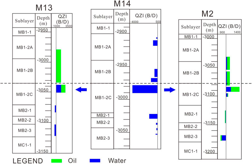
FIGURE 8. Downhole flow profile at wells M2 and M13 after injecting water from Well M14 (note: QZI represents the downhole zonal inflow rate).
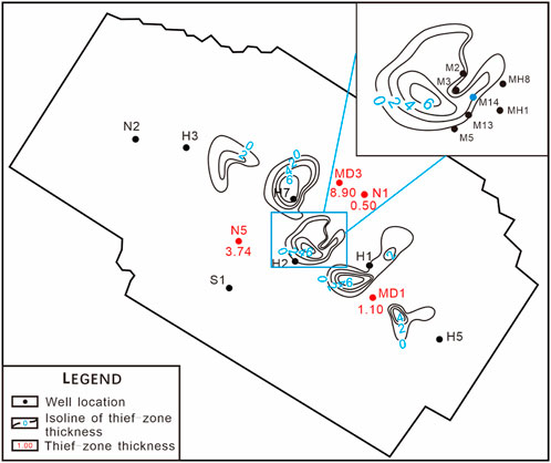
FIGURE 9. Well locations and planar distributions of thief zones identified by our method near Well M14 in Thief-zone unit 1 of MB1-2C.
As mentioned in Section 4, the planar distributions of thief zones in 14 members are generated. The thickness of thief zones varies a lot, with the largest value of 18.2 m at the tested wells. The thickness of thief zones mainly falls in the range of 1 m–8 m, which is relatively thin compared with the thickness of a member. The vertical distributions, planar distributions, and connectivity of thief zones for the Mishrif Formation in the H oilfield are discussed in this section.
Figure 10 depicts the distribution of the total area of thief zones in each member. It is to be noted that the total area of thief zones is the summation of the area inside the zero isoline of thief zone thickness. As shown in Figure 10, thief zones developed in 12 members, especially in MB1-2C, MB2-1, and MB2-2. While no thief zone developed in MC1-3 and MC2-2. Comparing with the distributions of sedimentary microfacies in these members, it can be found that thief zones tended to appear in the members developed in high-energy shoals, while the two members with no thief zone mainly developed shallow open sea and subtidal flats. This demonstrated that the distributions of sedimentary microfacies have a notable effect on the development of thief zones.
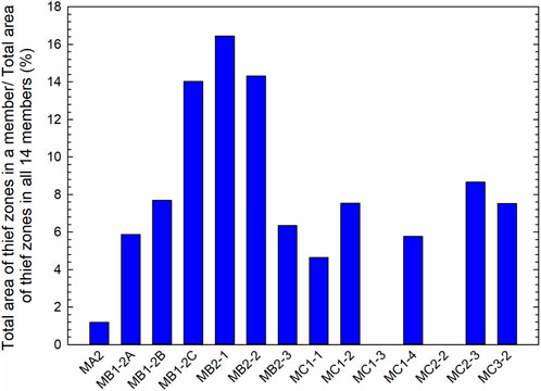
FIGURE 10. Distribution of the total area of thief zones in each member.
Figure 11 shows the planar distribution of thief zones in MB2-1. As shown in Figures 7, 11, the thief zones mainly developed in the center of the study region and extended along the short axis. Figures 12A,B show the planar distribution of thief zones in Thief-zone 2 of MB2-1 together with the tectonic line of MB2-1 and the planar distributions of sedimentary microfacies of MB2-1. As shown in these two figures, it can be concluded that the distributions of sedimentary microfacies have great contributions to the development of thief zones, while tectonism has less effect on the development of thief zones. Moreover, most of the thief zones developed in the high-energy shoals, such as algal mound, mussel clastic shoal, and intraclastic shoal.

FIGURE 11. Planar distribution of thief zones in MB2-1: (A) Thief-zone unit 1, (B) Thief-zone unit 2, and (C) Thief-zone unit 3.
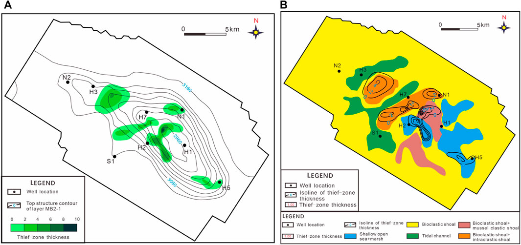
FIGURE 12. Planar distribution of thief zones in Thief-zone 2 of MB2-1 together with (A) tectonic line of MB2-1 and (B) sedimentary microfacies of MB2-1.
Since the sedimentary microfacies shown in Figure 13 is the dominant sedimentary microfacies in MB2-1, it may show discrepancies when describing the distribution of the high-energy shoals in the three thief-zone units of MB2-1. Hence, the density of high-energy shoal in the three thief-zone units of MB2-1 at 104 wells can be calculated. The density of a high-energy shoal is defined by the following equation:
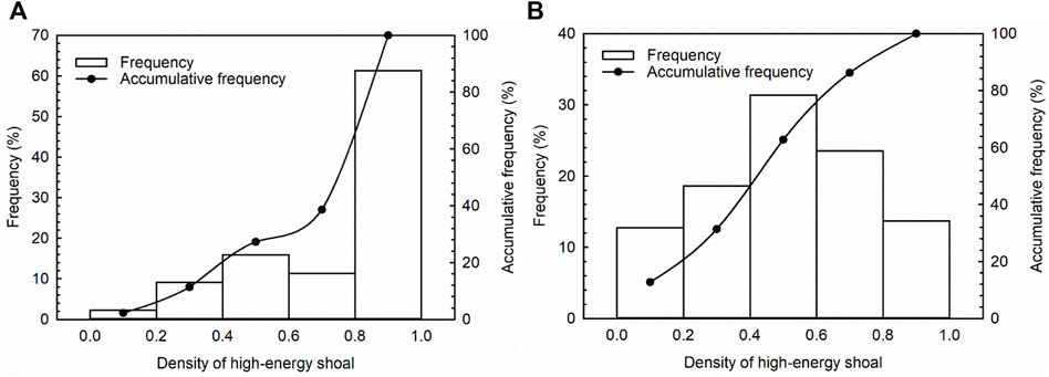
FIGURE 13. Density of high-energy shoals in the three thief-zone units of MB2-1 at 104 wells: (A) region where thief zones developed and (B) region where no thief zone developed.
As can be seen in this equation, the values of the density of high-energy shoal fall in the range of 0–1. As the thickness of the high-energy shoal increases, the density of the high-energy shoal increases. Figure 13 summarizes the density of high-energy shoals in the three thief-zone units of MB2-1 at 104 wells. Figures 13A,B show the density of high-energy shoals in the regions where thief zones developed and where no thief zone developed, respectively. As can be seen in these figures, 61.4% of the density of high-energy shoals is larger than 0.8 in the region where thief zones developed, while 86.3% of the density of high-energy shoals is smaller than 0.8 in the region where no thief zone developed. This indicates that the thief zones tended to develop in the region where high-energy shoals developed.
Figures 14A,B describe the well profile with the description of thief zones along the short axis (SW-NE trending) and the long axis (NW-SE trending), respectively. As shown in Figure 14A, thief zones have good connectivity in MB1-2B, MB1-2C, and MB2-1. The thief zones with good connectivity mainly developed in the center of the oilfield, while several small-scale thief zones developed at the edge of the oilfield. In Figure 14B, it can be found that thief zones in MB1-2B, MB1-2C, MB2-1, MC1-4, and MC2-3 have relatively good connectivity. Moreover, thief zones in the SE region have a better connectivity than those in the NW region.
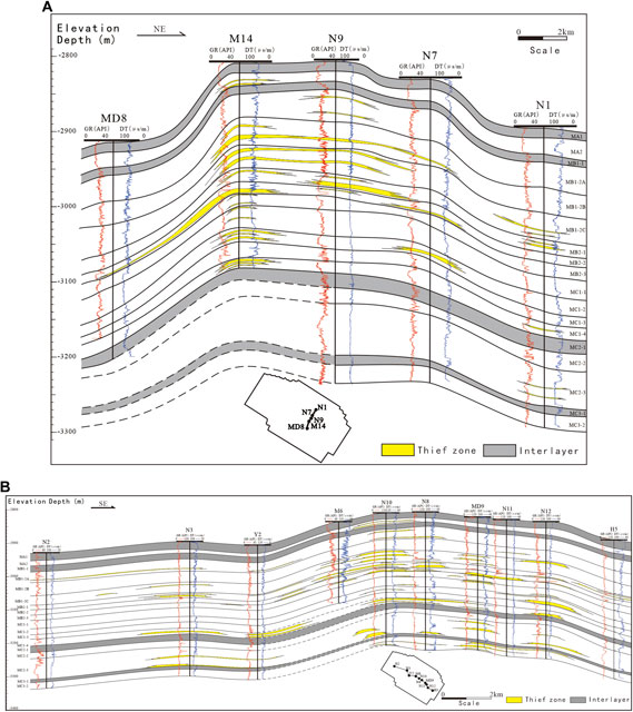
FIGURE 14. Well profile with the description of thief zones: (A) along the short axis (SW-NE trending) and (B) along the long axis (NW-SE trending).
In this research study, a simple approach to identify thief zones based on reservoir permeability obtained from well logging is developed. The lower limit values of the thief-zone permeability in each member are determined based on the dynamic production data, indicating that the thief zones identified by applying this criterion can reflect the production characteristics. After identifying the thief zones in each single well based on the newly developed criterion, the connectivity and distributions of thief zones in the regions far away from the well can be determined. To do this, a zonal inter-well recognition method is adopted in this research. This method is applied to identify thief zones for the Cretaceous Mishrif Formation in the H oilfield, Iraq. The results of the tracer test prove that this identification method is reliable. The distributions of thief zones for the Cretaceous Mishrif Formation in the H oilfield are discussed in this study. There are 12 members that develop thief zones, while two members (i.e., MC1-3 and MC2-2) do not develop thief zones. There are five members who have a high level of thief-zone development. They are MB1-2C, MB2-1, MB2-2, MC2-3, and MC3-2. The thief zones with good connectivity mainly developed in the center of the oilfield. Thief zones in the SE region have a better connectivity than those in the NW region. Moreover, the thief-zone development is mainly controlled by the sedimentary microfacies. Thief zones tend to develop in high-energy shoals.
The original contributions presented in the study are included in the article/Supplementary Material; further inquiries can be directed to the corresponding author.
RL: Methodology, funding acquisition, and writing—original draft; HD: Conceptualization, supervision, and funding acquisition; MF: Supervision; LH: Writing—review and editing; XX: Investigation; LZ: Validation; XG: Resources.
This study was supported by the project from the Exploration and Development Research Institute of Daqing Oilfield Company Ltd. (China) (Grant No. DQYT-1201002-2019-JS-71). The authors are grateful for the Open Fund of Engineering Research Center of Development and Management for Low to Ultra-Low Permeability Oil and Gas Reservoirs in West China, Ministry of Education, Xi’an Shiyou University to the first author (RL) (Grant No. KFJJ-XB-2020-2).
XG was employed by Exploration and Development Research Institute of Daqing Oilfield Company Ltd.
The remaining authors declare that the research was conducted in the absence of any commercial or financial relationships that could be construed as a potential conflict of interest.
The authors declare that this study received funding from Exploration and Development Research Institute of Daqing Oilfield Company Ltd. The funder had the following involvement in the study: collection of partial data.
All claims expressed in this article are solely those of the authors and do not necessarily represent those of their affiliated organizations, or those of the publisher, the editors, and the reviewers. Any product that may be evaluated in this article, or claim that may be made by its manufacturer, is not guaranteed or endorsed by the publisher.
Al-Ali, A., Stephen, K., and Shams, A. (2019). “Improved carbonate reservoir characterization: A case study from a supergiant field in southern of Iraq,” in SPE Middle East Oil and Gas Show and Conference, Manama, Bahrain, 18-21 March.
Al-Dhafeeri, A. M., and Nasr-El-Din, H. A. (2007). Characteristics of high-permeability zones using core analysis, and production logging data. J. Pet. Sci. Eng. 55, 18–36. doi:10.1016/j.petrol.2006.04.019
Al-Mimar, H. S., Awadh, S. M., Al-Yaseri, A. A., and Yaseen, Z. M. (2018). Sedimentary units-layering system and depositional model of the carbonate Mishrif reservoir in Rumaila oilfield, Southern Iraq, Model. Earth. Syst. Env. 4, 1449–1465.
Aqrawi, A. A. M., Thehni, G. A., Sherwani, G. H., and Kareem, B. M. A. (1998). Mid-Cretaceous rudist-bearing carbonates of the Mishrif formation: An important reservoir sequence in the mesopotamian basin, Iraq. J. Pet. Geol. 21 (1), 57–82. doi:10.1111/j.1747-5457.1998.tb00646.x
Batycky, R. P., Thiele, M. R., Baker, R. O., and Chung, S. (2008). Revisiting reservoir flood-surveillance methods using streamlines. SPE Reserv. Eval. Eng. 11, 387–394. doi:10.2118/95402-pa
Bromhead, A., van Buchem, F. S., Simmons, M. D., and Davies, R. B. (2022). Sequence stratigraphy, palaeogeography and petroleum plays of the cenomanian – turonian succession of the arabian plate: AN updated synthesis. J. Petroleum Geol. 45 (2), 119–161. doi:10.1111/jpg.12810
Chen, Q., Gerritsen, M. Q., and Kovscek, A. R. (2008). Effects of reservoir heterogeneities on the steam assisted gravity drainage process. SPE Reserv. Eval. Eng. 11, 921–932. doi:10.2118/109873-pa
Feng, Q., Wang, S., Gao, G. Q., and Li, C. Y. (2010). A new approach to thief zone identification based on interference test. J. Pet. Sci. Eng. 75, 13–18. doi:10.1016/j.petrol.2010.10.005
Fouad, S. F., and Sissakian, V. K. (2011). Tectonic and structural evolution of the mesopotamia plain. Iraqi Bull. Geol. Min. 4, 33–46.
Fouad, S. F. (2010). Tectonic and structural evolution of the mesopotamia foredeep, Iraq. Iraqi Bull. Geol. Min. 6 (2), 41–53.
Fouad, S. F. (2015). Tectonic map of Iraq, scale 1: 1000 000, 2012. Iraqi Bull. Geol. Min. 11 (1), 1–7.
Fu, C., Guo, T., Liu, C., Wang, Y., and Huang, B. (2019). Identification of the thief zone using a support vector machine method. Processes 7 (6), 373. doi:10.3390/pr7060373
Ghafoori, M. R., Roostaeian, M., and Sajjadian, V. A. (2009). Secondary porosity: A key parameter controlling the hydrocarbon production in heterogeneous carbonate reservoirs (case study). Petrophysics 50 (1), 67–78.
He, C. Z., and Hua, M. Q. (1998). Fractal geometry description of reservoir pore structure. Oil Gas. Geol. 1, 17–25.
He, L., Zhao, L., Li, J., Ma, J., Lui, R., Wang, S., et al. (2014). Complex relationship between porosity and permeability of carbonate reservoirs and its controlling factors: A case study of platform facies in pre-caspian basin. Petroleum Explor. Dev. 41 (2), 225–234. doi:10.1016/s1876-3804(14)60026-4
He, Y., Yang, C. M., Ying, J., and Yan, J. H. (2002). A new method for measuring the quantitative pore throat volume. J. Southwest Pet. Inst. 3, 5–7.
Izgec, B., and Kabir, S. (2009). Identification and characterization of high-conductive layers in waterfloods. SPE Reserv. Eval. Eng. 14, 113–119. doi:10.2118/123930-pa
John, D., Hans, V. D., Maersk, O., and Arve, O. N. (2013). “Interwell communication as a means to detect a thief zone using DTS in a Danish Offshore well,” in Proceedings of the SPE Offshore Technology Conference, Houston, TX, USA, 6-9 May.
Kong, D., Lian, P., Zheng, R., and Li, Y. (2021). Performance demonstration of gas-assisted gravity drainage in a heterogeneous reservoir using a 3D scaled model. RSC Adv. 11, 30610–30622. doi:10.1039/d1ra03859a
Li, G. J., Liang, J., and Li, W. (2008). A study on the method to identify large pore paths using well logging data. Oil Gas. Field Surf. Eng. 9, 11–12.
Li, D., Yang, J., and Lu, D. (2015). Thief zone identification based on transient pressure analysis: A field case study. J. Pet. Explor. Prod. Te. 6 (1), 63–72. doi:10.1007/s13202-015-0168-8
Li, R., Chen, Q., Deng, H., Fu, M., Hu, L., Xie, X., et al. (2021). Quantitative evaluation of the carbonate reservoir heterogeneity based on production dynamic data: A case study from cretaceous Mishrif Formation in halfaya oilfield, Iraq. J. Pet. Sci. Eng. 206, 109007. doi:10.1016/j.petrol.2021.109007
Liao, M. G., Li, S. L., and Tan, D. H. (2001). Relationship between permeability and mercury injection parameters curve for sandstone reservoir. J. Southwest Pet. Inst. 4, 5–8.
Liu, L., Zheng, X., He, E., Liu, F., and Luo, H. (2016). “Findings and challenges of high permeability zone on water injection pilots in Iraqi carbonate reservoirs,” in Abu Dhabi International Petroleum Exhibition & Conference, Abu Dhabi, UAE, 7-10 November (Society of Petroleum Engineers).
Nasser, M. E. (2018). Stratigraphic sequence and basin development of the Mishrif Formation in selected oil fields in the Mesopotamian zone, Southeastern Iraq. IJAERS 5, 45–53. doi:10.22161/ijaers.5.5.6
Simmons, M. D., Sharland, P. R., Casey, D. M., Davies, R. B., and Sutcliffe, O. E. (2007). Arabian Plate sequence stratigraphy: Potential implications for global chronostratigraphy. GeoArabia 12 (4), 101–130. doi:10.2113/geoarabia1204101
Wang, J., Guo, R., Zhao, L., Li, W., Zhou, W., and Duan, T. (2016). Geological features of grain bank reservoirs and the main controlling factors: A case study on cretaceous Mishrif formation, H oilfield, Iraq. Pet. Explor. Dev. 43 (03), 367–377.
Wang, X., Xia, Z. J., Zhang, H. W., Liu, X. P., Li, X. Q., and Zhang, L. J. (2002). Using injection profile log data to distinguish macropore formation. Well Logging Technol. 26, 162–164.
Wang, Y. (2016). Carbonate reservoir genesis and distribution of cretaceous Mishrif formation in halfaya oil field Iraq. China, Sichuan: Chengdu University of Technology.
Wang, Y. Q., Chen, F. H., Gu, H. J., Zhou, H. Z., Nie, Z. R., Liu, F. K., et al. (2011). Using tracer to study interwell water flow predominant channel. Xinjiang Pet. Geol. 32, 512–514.
Wei, C., Zheng, J., Ouyang, X., Ding, Y., Ding, M., Lin, S., et al. (2019). “Thief zone characterization and its impact on well performance based on surveillance data, experimental data and theoretical analysis for a carbonate reservoir,” in SPE Reservoir Characterization and Simulation Conference and Exhibition, Abu Dhabi, UAE, 17-19 September.
Zhang, L., Li, R., Deng, H., Fu, M., Hu, L., Guo, X., et al. (2021). Identification, distribution characteristics, and effects on production of interlayers in carbonate reservoirs: A case study from the cretaceous Mishrif formation in halfaya oilfield, Iraq. J. Pet. Sci. Eng. 202, 108571. doi:10.1016/j.petrol.2021.108571
Zhao, J., Zhang, S., and Qi, C. (2010). The methods of split and using these methods with an example. Inn. Mong. Petrochem. Ind. 3, 29–31.
Zheng, A. L., Liu, D. H., and Shao, Y. L. (2011). Oil sand potential and development measures for complex fault-block reservoir. Special Oil Gas Reservoirs 18 (1), 93–95.
Hi effective thickness of the ith layer
Hj effective thickness of the jth layer
Ki permeability of the ith test point
Kp_aver average permeability of the corresponding perforated interval
Kt_aver average permeability of all the perforated intervals
m number of layers
Mi production split coefficient used in the KH method
qo unit oil production of a well
qoi unit oil production of the ith layer
Keywords: thief zone, production data, carbonate reservoir, Mishrif Formation, Iraq
Citation: Li R, Deng H, Fu M, Hu L, Xie X, Zhang L and Guo X (2023) Identification method of thief zones in carbonate reservoirs based on the combination of static and dynamic data: A case study from the Cretaceous Mishrif Formation in the H oilfield, Iraq. Front. Energy Res. 10:1043231. doi: 10.3389/fenrg.2022.1043231
Received: 13 September 2022; Accepted: 29 September 2022;
Published: 10 January 2023.
Edited by:
Debin Kong, University of Science and Technology Beijing, ChinaReviewed by:
Hongjian Zhu, Yanshan University, ChinaCopyright © 2023 Li, Deng, Fu, Hu, Xie, Zhang and Guo. This is an open-access article distributed under the terms of the Creative Commons Attribution License (CC BY). The use, distribution or reproduction in other forums is permitted, provided the original author(s) and the copyright owner(s) are credited and that the original publication in this journal is cited, in accordance with accepted academic practice. No use, distribution or reproduction is permitted which does not comply with these terms.
*Correspondence: Hucheng Deng, ZGVuZ2h1Y2hlbmdAY2R1dC5jbg==
Disclaimer: All claims expressed in this article are solely those of the authors and do not necessarily represent those of their affiliated organizations, or those of the publisher, the editors and the reviewers. Any product that may be evaluated in this article or claim that may be made by its manufacturer is not guaranteed or endorsed by the publisher.
Research integrity at Frontiers
Learn more about the work of our research integrity team to safeguard the quality of each article we publish.