 Yue Jiang
 Liqiang Duan
 Liping Pang
- School of Energy, Power and Mechanical Engineering, National Thermal Power Engineering & Technology Research Center, Key Laboratory of Power Station Energy Transfer Conversion and System (North China Electric Power University), Ministry of Education, North China Electric Power University, Beijing, China
Solar-aided coal-fired power generation (SACPG) technology is an effective method of solar energy utilization. It could balance the demand of carbon dioxide emission reduction and renewable energy efficient power generation and promote carbon peaking and carbon neutralization. Accurate analysis of the share of solar energy in the unit output power could benefit the selection of the best integration scheme and exploitation of solar energy for further research. A novel solar contribution evaluation method of an SACPG system is put forward. The exergy is taken as the evaluation benchmark, and the method can be applied in an SACPG system with multiple integration positions with solar energy. The solar energy input from different positions in the system is analyzed separately. The solar energy input positions and the impact of solar exergy destruction on the solar energy contribution are considered. The proposed method also analyzes the flow direction and destruction of each solar exergy in different parts of the SACPG system and expresses the solar contribution in the electricity generated by each stage steam turbine in the form of a theoretical formula. Ultimately, the solar exergy contribution in the whole SACPG system is calculated by accumulating each result. Furthermore, the new method is applied to a tower solar-aided coal-fired power generation (TSACPG) system with thermal energy storage (TES) for comparative analysis. Compared with other solar contribution evaluation methods, the comprehensiveness and accuracy of the novel method are analyzed. Meanwhile, the exergy destruction distributions of the TSACPG system are revealed. The method can also be further used to excavate the application potential of solar energy in coal-fired units and provide theoretical support for highly efficient utilization of solar energy.
Introduction
Solar energy has been essentially required in the field of power supply all over the world due to its reproducibility, cleanability, and ubiquity (Agarwal et al., 2020; Manzolini et al., 2021; Rushdi et al., 2021). With the proposal of carbon peaking and carbon neutralization targets in China (Ding et al., 2019), the sustainable and effective contribution from solar energy has become an important topic (Qin et al., 2020). Solar-aided coal-fired power generation (SACPG) technology is considered to be an effective technique to integrate clean energy with traditional fossil energy (Wu et al., 2016). The share of power generation equipment could reduce the instability and high cost of individual exploitation of clean energy, and both the utilization scale and scope are also improved (Zhu et al., 2017). SACPG technology can not only reduce the coal expenditure in coal-fired units but also provide a good scheme for switching between various energy sources in the future, which can contribute to carbon peaking and carbon neutralization in a fast and feasible way.
Many scholars have carried out relevant research works in the field of SACPG technology and put forward diverse combination approaches of the solar energy and coal-fired power generation system. Trough solar energy was first considered to be the thermal load for heating boiler feedwater and replaced multi-stage regenerators. Qin J (Qin et al., 2017) discussed the impacts of several solar energy acquirement ways on the SACPG system. Non-concentrated and concentrated solar receivers were used to take the place of high-pressure and low-pressure regenerators in this study, respectively. Moreover, the thermodynamic analysis such as the solar to electricity efficiency and economic analysis have also been compared. Yan Q (Yang et al., 2011) put forward four integration schemes, in which extraction steam was replaced by solar energy to heat feedwater in different positions. The solar to electricity efficiency could reach 36.5% for the solar heat at 260°C, as the results presented, and it proved that the SACPG technology had advantages in the power generation efficiency, fuel consumption, and steam consumption. Yan Q (Yan et al., 2010) further calculated the results of replacement for each stage of the regenerator by solar energy and conducted a comparative study. It was found that the low-temperature solar energy, which was difficult to be used, could also be adopted to heat the feedwater in a low-pressure regenerator, and it widened the limitation of solar energy in SACPG technology. Hou H (Hou et al., 2015) established a set of calculation model of trough solar-assisted feedwater heating, and the improved matrix heat balance equation was used to improve the calculation speed. The results showed that when solar energy was used to replace the high-pressure regenerators, it could be found that the boiler exhaust temperature and the consumption of coal would be decreased and the boiler efficiency would be increased. Based on the exergy analysis method, Hong H (Hong et al., 2017) derived the formula expression of electric power output of SACPG systems. In this research, solar energy was also used as an energy source of the feedwater heating, and the effects of solar radiation, unit load, and other factors on the solar thermal performance were also discussed. Qin J (Qin and Hu, 2017) investigated the configuration of solar feedwater preheaters and operation strategy of those and 12 possible configuration–operation strategies are summarized. In addition, the impacts of solar irradiation intensity and solar receiver area on the solar to electricity efficiency were also studied in the proposed configuration–operation strategies. In actual demonstration application, the Colorado Integrated Solar Project (CISP) (Zhao et al., 2014) implemented the scheme that the solar energy was used to heat feedwater in the coal-fired power unit and the coal consumption was reduced notably. The integration scheme did not intervene in the normal power generation of the unit.
With the improvement of solar energy utilization level, the technology of tower solar has been widely used, which can improve the working fluid temperature to a higher level or replace more thermal load of the boiler feedwater, and the related research works are increasingly abundant. Wang J (Wang et al., 2019a; Wang et al., 2019b) built the model of the tower solar-aided coal-fired power generation (TSACPG) system and proposed a new optimization algorithm called as the general integration optimization approach to obtain the best TSACPG scheme from many alternatives. In this study, the tower solar was applied to heat the feedwater, and the general laws of solar energy distribution for heating were revealed. In the TSACPG system, tower solar can also be applied to heat working medium with higher temperature, such as main steam and reheat steam. Yu X (Duan et al., 2017) established the TSACPG model in the TRNSYS platform and studied the dynamic thermal performance of the TSACPG system in the fuel-saving mode. The annual performance analyses of the TSACPG system in terms of thermodynamics and economics were studied in the case study. Li C (Li et al., 2018a; Li et al., 2018b) proposed the scheme of integrating tower solar and conventional single reheat coal-fired power unit. In this research, solar energy was applied to meet the partly thermal load of the reheater in the boiler, and the performances of the proposed scheme in terms of thermodynamics and economics were analyzed from the perspectives of the boosting power mode and saving coal mode. The researchers also discussed the typical daily performances of the TSACPG system with the thermal energy storage (TES) system under different operation loads. Zhang M (Zhang et al., 2016; Zhang et al., 2017) proposed two integrating scenarios of the coal-fired boiler and tower solar. In the proposed scenarios, both the superheated steam and supercooled water of boiler were heated by the solar energy, which could reduce the coal consumption. Liu H (Liu et al., 2020) put forward the use of the trough solar to preheat feedwater, replacing regenerators and at the same time, the tower solar was used to heat the superheated steam replacing the economizer, water-cooled wall, and some superheaters in the boiler. It was found that more solar energy could be introduced into coal-fired units under the same cost conditions. Zhu Y (Zhu et al., 2018) put forward seven integration schemes and five of them were devised for tower solar arrangement and two for trough solar arrangement. After comparison analysis, the solar tower had a higher energy grade than the trough solar. He also obtained the best integration scheme based on both the solar to electricity efficiency and the decrease of coal utilization.
In various SACPG technology research works, less effort has been made on the study of evaluation method of the solar energy contribution in the SACPG system. Considering the increasing demand for carbon dioxide emission reduction, the share of solar energy in the output power of the SACPG system become increasingly significant, which can be used to estimate the degree of carbon emission reduction. At present, the simple energy proportional distribution method based on the first law of thermodynamics is widely applied to calculate the contribution of solar energy in the SACPG system (Zhang et al., 2019; Huang et al., 2020), and a few scholars analyzed the SACPG system based on the exergy method and calculated the solar contribution by the exergy proportional distribution method, which was similar with the energy proportional distribution method (Hou et al., 2016). These methods applied in previous research works do not consider both the quantity and quality differences between solar energy and coal energy, and when there are multiple integration locations in the coal-fired unit, the impact caused by the different location of solar energy input to coal-fired units is also neglected in these methods. Moreover, when the energy from different sources enters the working medium in the system, the changes and exergy destructions at different positions are also not reflected. These factors will have a dramatical impact on the final result of solar energy contributing in the SACPG system. In this study, a new evaluation method of solar energy contribution in the SACPG system is proposed, in which the exergy is taken as the calculation benchmark, and the differences of exergy sources are distinguished and the proposed method can be applied in the multi-point integration system, in which solar energy is input into the coal-fired power unit from several different integration positions. The solar energy input from different positions is analyzed separately, and the different influences on the SACPG system are also taken into consideration. Furthermore, the distributions of solar exergy destruction in the system are also discussed. Ultimately, multiple results are accumulated and calculated to obtain the final solar energy contribution of the SACPG system. Simultaneously, other three evaluation methods are selected to compare with the proposed new method in this study.
TSACPG system description
The general SACPG system mainly includes two parts, which are solar field and traditional coal-fired unit. In this study, a new tower solar-aided coal-fired power generation (TSACPG) system with TES is proposed, in which solar energy can be input into the coal-fired unit via three integration locations. The proposed system is separated into the tower solar part and double-reheat coal-fired power unit part. The tower solar part contains the receiver, the heliostat field, double-molten salt tank, several molten salt heat exchangers (MSHEs), and other auxiliary equipment. The coal-fired power unit includes boiler, turbines, condenser, regenerators, deaerator, generator, and other auxiliary equipment. When the sunlight is available, the solar energy is reflected by the heliostat to the receiver arranged on the tower and the low-temperature molten salt, which is stored in the cold tank flows into the receiver. The solar energy is transferred into the molten salt; the temperature of molten salt is raised, and then, it returns to the hot tank. On the basis of the energy cascade utilization, the molten salt with high-grade energy flows out of the hot tank and imports the carried solar energy into the first reheat extraction steam, second reheat extraction steam, and the feedwater through three MSHEs, so as to realize tower solar-aided coal-fired power generation. Specifically, as shown in Figure 1, the two MSHEs named as MSHE-FRH and MSHE-SRH are arranged in parallel to transfer the solar energy to the extraction steam first reheater and the second reheater in the boiler, respectively. After the heat exchange is completed in MSHE-FRH and MSHE-SRH, these two streams of molten salt outflow and converge in MSHE-FW, and the mixed molten salt is used to heat the whole feed water, which flows out of the DEA and then return to the cold tank. The feedwater is heated up to the design parameters and flow back to the boiler inlet. Therefore, the thermal load of all high-pressure feed water regenerators is replaced by MSHE-FW.
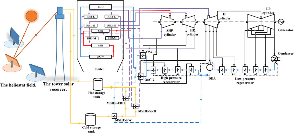
FIGURE 1. Diagram of the tower solar-aided coal-fired power generation system with TES (red solid line: main steam; purple solid line: reheat steam; blue solid line: water; yellow solid line: molten salt; and dotted line: extracted working medium).
Unlike other integration methods, the tower solar energy used in this study can heat the molten salt to a high temperature of about 560°C. Therefore, according to the principle of energy matching, the high-grade molten salt energy is used to heat the high-grade first and second reheat extracted steams in the boiler, and then the remaining low-grade molten salt energy is used to heat the boiler feedwater with low-grade energy. In this way, the solar energy can be integrated with coal-fired units at multiple positions and the cascade utilization of high-temperature solar energy is realized. Moreover, the solar energy has also been used more sufficiently.
A 660-MW ultra-supercritical double-reheat coal-fired unit in service in China is selected as the traditional coal-fired unit part, and the system is simulated using EBSILON software, which is commonly applied for the simulation of different thermodynamic cycles (Soares et al., 2021; Wang et al., 2021; Świerzewski et al., 2021). The simulation results of the coal-fired power generation system under 100% THA load (turbine heat acceptance), 75% THA load, and 50% THA load show strong agreements with the design values, which have been validated in the previous study (Jiang et al., 2022). So, the model is proven to be reliable for further study.
The compositions of coal applied in the coal-fired unit in this study are shown in Table 1.
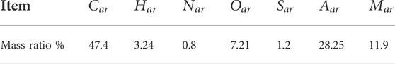
TABLE 1. Coal elemental analysis of the TSACPG system.
When comparing different solar energy contribution evaluation methods in the suggested TSACPG system, the consistency of parameters of the solar field is supposed to be guaranteed. So, the parameters of the tower solar part are uniformly set, as shown in Table 2, and the validation of the solar field model has been also implemented in a previous study (Jiang et al., 2022).
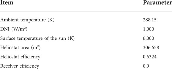
TABLE 2. Key parameters of the solar field (Jiang et al., 2022).
For the purpose of exploring the solar contribution of the TSACPG system in different loads, it is necessary to explore the maximum mass flow rates of the extraction steam from boiler reheaters heated by the solar energy under different loads. Since the MSHE-FW is arranged in series with MSHE-FRH and MSHE-SRH, as shown in Figure 1, the mass flow rate of the molten salt in MSHE-FW is the sum of mass flow rates in MSHE-FRH and MSHE-SRH for heating extraction steam. When the molten salt in MSHE-FW could replace all the thermal load of four-stage high-pressure regenerators and parameters of feedwater at the outlet of MSHE-FW could meet the boiler inlet designed value, the molten salt mass flow rate reaches the maximum, and both MSHE-FRH and MSHE-SRH can heat the most extraction steam. Furthermore, the maximum extraction steam mass flow rate can be gained with the help of some approaches such as regulating the rate of flue gas recirculation and the opening degree of flue gas damper in the boiler furnace. The results are shown in Table 3 (Jiang et al., 2022).

TABLE 3. Maximum extraction steam mass flow rates in different loads in the TSACPG system.
Exergy analysis model
Exergy of coal
where
Exergy of solar
where
Heliostat field
where
Tower solar receiver
where
Molten salt heat exchanger
where
The physical exergy of each state point can be considered as follows:
where
Solar contribution evaluation method
In order to illustrate the comprehensiveness and accuracy of the solar contribution evaluation method proposed in this study, three other common solar contribution evaluation methods are selected for comparison analysis. Among them, both method I and method II take “energy” as the evaluation benchmark; method IV proposed in this study takes “exergy” as the evaluation benchmark, which is the available part in the energy. Compared with method I and method II, method IV eliminates the deviation of effective energy from different sources. Compared with method III, method IV proposed in this study takes into account the impact of different input positions of solar energy on the results, and it will make the results more accurate.
Method I: Energy proportional distribution
Method I is the most common solar energy contribution evaluation method. The energy imported from the solar and the coal combustion is regarded as the same energy grade when they are input into the same TSACPG system. The position of the solar energy input is not distinguished and considered. When analyzing the solar contribution in the TSACPG system, only the difference of energy “quantity” is considered, according to the first law of thermodynamics, that is, the calculation is merely on the basis of the proportion of solar energy input. In accordance with method Ⅰ, the expression formula of power generated from solar is as follows (Jiang et al., 2021):
where
Method II: Thermal sub-cycle division
Method II splits the double-reheat Rankine cycle into three sub-cycles approximately, and the corresponding T-s diagram is shown in Figure 2. These three sub-cycles are main steam cycle (Cycle-I, c-d-e-f-k-c), the first reheat cycle (Cycle-II, c-k-f-g-h-l-b-c), and the second reheat cycle (Cycle-III, a-b-l-h-i-j-a), and the sum of the work of these three sub-cycles is the overall system output power (Xin et al., 2020). When the solar energy is adopted as an external heat source to replace part of the coal for heating the working medium, the replaced heating position in these three cycles can be located in the T-s diagram, and then the corresponding output work can be calculated. If there are multiple replaced heating positions, the corresponding calculated power can be accumulated and the result is the solar output power. This method also refers to the first law of thermodynamics, only the difference of energy “quantity” is considered. However, difference of integration position between solar energy and coal-fired power generation units has been considered, and it should be more accurate than method I (Hou et al., 2016).
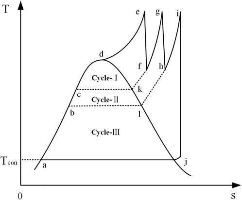
FIGURE 2. Thermodynamic T-s diagram of the double-reheat Rankine cycle.
In the proposed integration scheme of this study, solar energy heats all boiler feedwater replacing the heat load of four-stage regenerators, part of the steam from first reheater and second reheater in the boiler, corresponding to the red line part of the endothermic process in these three sub-cycles in Figures 3, 4. In order to determine the corresponding output power, the endothermic process of each sub-cycle is further divided here. Each sub-cycle is divided into n micro-cycles according to different endothermic process, such as
where
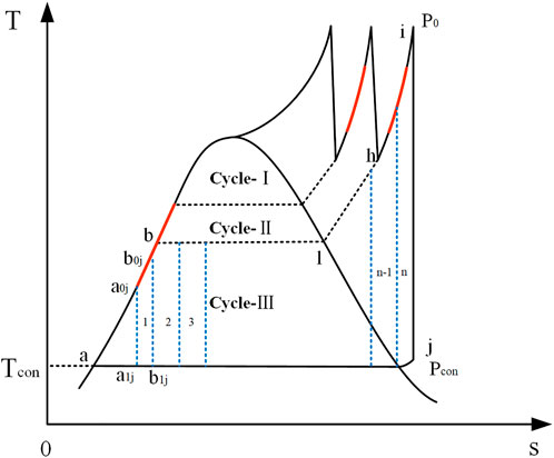
FIGURE 3. Thermodynamic T-s diagram of micro-cycle illustration.
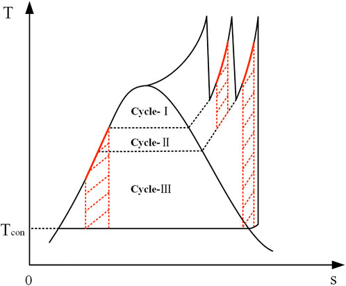
FIGURE 4. Thermodynamic T-s diagram of power generated by solar energy illustration.
When the output powers of all n micro-cycles are summed up, the whole sub-cycle output power can be obtained by formula (14).
where
After the aforementioned analysis, it is found that the sum of output power corresponding to the solar heating process in each sub-cycle is the total solar output power in the TSACPG system, and it can be illustrated by the red shaded part in the T-s diagram, as shown in Figure 4.
Method III: Exergy proportional distribution
On the basis of the second law of thermodynamics, method III considers the energy grade difference between the solar energy and coal energy. Exergy is taken as the system input, and the proportion of the solar exergy in the total input has been calculated. When method III is applied to evaluate the solar contribution in the TSACPG system, the “quality” of energy is considered. Nevertheless, method III does not consider the difference of solar contribution caused by the different integration positions, where the solar energy is imported. According to method III, the calculation method of solar output power is as follows:
The calculation methods of
Method IV: Exergy cumulative calculation
Method IV is a new method proposed in this study, and it makes a specific analysis of the evaluation of solar energy contribution in the TSACPG system based on exergy, which not only takes into account the difference between the solar exergy and the coal exergy but also distinguishes the contribution of solar energy imported from different integration positions to the whole system. In the suggested TSACPG system in this study, solar energy enters into the working medium of coal-fired unit from three positions, which are the boiler feedwater part and the first and the second reheat steam parts. In method IV, the three parts of solar energy are considered separately, and the power generated from each part in the TSACPG system is calculated independently. Finally, the accumulation of three solar energy contributions is carried out, and the total solar contribution in the TSACPG system is summarized.
For the purpose of analyzing the solar contribution of the TSACPG system better, the system is simplified, as shown in Figure 5. The boiler is simplified as the superheater part, the first reheater part, and the second reheater part. The turbine is divided into three parts, which are the super-high-pressure cylinder (SHP), the high-pressure cylinder (HP), and the intermediate-pressure and low-pressure cylinder (IP–LP). The regenerator part is simplified as the high-pressure regenerator and low-pressure regenerator. From the integration scheme put forward in this study, both solar energy and coal energy are imported at the integration positions that are the high-pressure regenerator, the first reheater part, and the second reheater part.
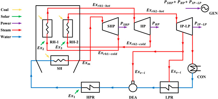
FIGURE 5. Simplified TSACPG system.
The exergy destructions of the main equipment in the TSACPG system and the distributions of solar exergy destruction are analyzed in this method. The most important equipment in coal-fired units is boilers and turbines, in which the boiler exergy destruction accounts for the main part of the whole system (Li et al., 2014). The exergy destruction in the boiler is produced by the heat transfer process between the working medium and flue gas released from coal combustion and distributed in each heat exchanger of the boiler. In the proposed system, the solar exergy is transferred to the working medium through three MSHEs outside the boiler. So, the solar exergy is not involved in the heat exchange process in the boiler, and there is no solar exergy destruction in the boiler. The influence on the solar contribution from the solar exergy destruction mainly occurs on the turbine. However, the exergy destructions of other parts of the system account for a very small proportion and the solar exergy destruction can be ignored. Therefore, the solar exergy destruction in the turbine is analyzed in detail, as shown in Figure 6.
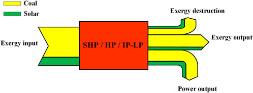
FIGURE 6. Illustration of exergy destruction distribution in the turbine cylinder.
The study is consistent with the notion that the proportion of solar exergy in the input is the same as those in the exergy output, power output, and exergy destruction in different cylinders of the turbine (Zhu et al., 2016). Therefore, the exergy destruction distribution of these three main parts of the steam turbine, namely, SHP, HP, and IP–LP, can be obtained.
The following is a specific analysis of the contribution of solar energy imported into three different solar integration locations.
First, the contribution of solar exergy imported into the feedwater is calculated. Here, for the convenience of expression, this part of solar exergy is named Solar Exergy A. In the SHP, the output power of Solar Exergy A can be expressed by the following formula:
where
In the HP, the output power of Solar Exergy A can be expressed using the following formula:
where
In the IP–LP, the power output of Solar Exergy A can be expressed using the following formula:
where
In addition, there is extraction steam from the turbine cylinder for heating the boiler feedwater and the extraction steam also carries part of the solar exergy to the feedwater via the regenerator. This part of the solar exergy can also contribute for power generation in the turbine through the working medium circulation of the whole system. Therefore, the power generated by this part of solar exergy in the turbine can be calculated using the following formula:
where
Based on the aforementioned analysis, the contribution of Solar Exergy A is as follows:
where
Second, the contribution of solar exergy imported into the first reheat steam is calculated. For the same reason, this part of solar exergy is named Solar Exergy B. Since this part of solar exergy does not flow through the superheated part of the boiler and SHP, the output power of Solar Exergy B starts from the HP, according to the flow direction of the working medium. The power output of Solar Exergy B in the HP can be expressed using the following formula:
where
In the IP–LP, the power output of Solar Exergy B can be expressed by the following formula:
where
Similar to the solar exergy imported into the feedwater, Solar Exergy B also exists in the extraction steam and contributes for power generation in the turbine, which is expressed by the following formula:
where
According to the analysis of this part, the contribution of Solar Exergy B is as follows:
where
Last, the contribution of solar exergy imported into the second reheat steam is calculated, and this part of solar exergy is named as Solar Exergy C. The work of this part solar exergy in the system starts from the IP–LP. After considering the effect of steam extraction of the turbine, the power output can be calculated by the following formula:
where
Based on the aforementioned separate analysis of these three solar energy inputs, the solar energy contribution in the TSACPG system is supposed to be finally obtained as follows:
where
Result and analysis
Solar contribution
According to the aforementioned four evaluation methods, the solar contributions based on the maximum steam extraction under different loads in the TSACPG system are calculated, including the solar output power and the proportion of solar output power in the overall system. The results are shown in Figure 7.
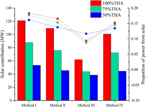
FIGURE 7. Solar contribution with different evaluation methods in the TSACPG system under 100% THA, 75% THA, and 50% THA loads.
In terms of the differences of benchmarks among different evaluation methods, methods I and II take “energy” as the evaluation benchmark, and methods III and IV take “exergy” as the evaluation benchmark. With the same energy, the solar exergy is much lower than that released by the coal combustion. Therefore, when methods III and IV are applied to evaluate the same system, the solar contributions are lower than those of methods I and II. It is shown in Figure 7. Specifically, under the 100%, 75%, and 50% THA loads, the solar output powers obtained by method I are 120.895, 87.646, and 53.269 MW, respectively, accounting for 0.1832, 0.1771, and 0.1614, respectively. When method II is applied, the solar output power obtained are 109.209, 75.856, and 45.380 MW, and the solar proportions in the system are 0.1655, 0.1532 and 0.1375. It is evident that the evaluation results of method II are lower than those of method I under different loads. This is because that solar energy is taken as a whole to input the coal-fired unit when method I is applied. The factor is ignored that the solar input at different integration positions will have different effects on the overall system. When the working medium circulates in the system, it has different capacities to do work at different integration positions and the increases of work capacity of the working medium are also different due to different integration points. For the evaluation of method II, the Rankine cycle is split into multiple sub-cycles according to the pressure and temperature of the working medium in the endothermic process and every sub-cycle corresponds to the output power. In this way, as long as the endothermic process corresponding to the solar energy providing is located, the output power corresponding to each solar energy input can be obtained, and the overall solar contribution can also be gained. Based on the benchmark of “energy,” method II is more accurate than method I.
When evaluating the multiple energy source thermodynamic system, the second law of thermodynamics also needs to be used. The same energy from different sources will have different effective energy, which is “exergy.” The difference of “exergy” will also cause evaluation deviation. Methods III and IV assess the difference of solar exergy and coal exergy. When compared with methods I and II, the results of solar contribution are relatively less because solar exergy is much less than the coal exergy when they carry the same amount of energy. Compared with method IV, method III also neglects the integration position that solar exergy imports. In terms of exergy destruction analysis in method III, exergy destruction of each equipment in the system is taken as a whole to calculate without reasonably separating it in essence. During the actual operation of the system, the exergy destruction of different equipment varies significantly and the boiler exergy destruction accounts for the main part of the whole system (Yang et al., 2013). In the evaluation of method III, it is equivalent to evenly distributing the coal exergy and solar exergy to each sub-equipment in the system, and the default assumption in the calculation is different from the actual situation. Therefore, there is also a dramatical deviation in the evaluation results of method III. Method IV proposed in this study takes “exergy” as the benchmark and analyzes the solar exergy imported into different integration positions of the coal-fired unit separately. In addition, the proportion of solar exergy in the output power of each cylinder of the turbine is obtained, and the solar exergy in the extraction steam from the turbine is also further analyzed. Specifically, under the loads of 100%, 75%, and 50% THA, the solar output powers obtained by method III are 61.890, 43.580, and 38.568 MW, respectively, accounting for 0.0938, 0.0880, and 0.1169, respectively. When method IV is applied, the output powers generated from the solar obtained are 100.434, 72.164, and 44.353 MW, respectively, and the solar proportions in the system are 0.1522, 0.1458, and 0.1344, respectively. It is presented that the evaluation results of method IV are higher than that of method III under different loads. The reason for that is most solar exergy destruction does not occur in coal-fired units and most of them mainly occur in the heliostat field, tower solar receiver, and MSHEs. The exergy destruction in the boiler is produced by heat transfer between the flue gas and the working medium, which is irrelevant to the existing solar exergy that has been already imported into water/steam in MSHE before entering the boiler. So, the exergy destruction in the boiler only comes from the coal. Thus, the loss of coal exergy is relatively increased before entering the turbine, which causes the proportion of solar exergy in the turbine to increase compared to method III. Moreover, the solar contribution will be increased accordingly. Under the 100%, 75%, and 50% THA loads, it is increased by 62.28%, 65.59%, and 15.00%, respectively. Method III relatively underestimates the solar contribution in the TSACPG system.
Figures 8–10 reveal the specific solar output power in different cylinders under different loads. The yellow part represents the power generated from solar exergy in the feed water, the first and second reheat steams apart from extracted steam in different cylinders are named as “direct power” here. The green part represents the power generated from the solar exergy in extracted steam in different cylinders, which is named “extracted steam power” here. It can be presented from the figures that the extracted steam still accounts for a non-negligible proportion in the final solar contribution, especially in the IP–LP. Under the 100% THA load, the direct power values are 17.05, 15.67, and 44.18 MW in the SHP, HP, and IP–LP, respectively. The extracted steam power values are 1.64, 1.50, and 4.24 MW in the SHP, HP, and IP–LP, respectively. Under the 75% THA load, the direct power values are 11.97, 11.36, and 32.43 MW in the SHP, HP, and IP–LP, respectively. The extracted steam power values are 0.98, 0.93, and 2.64 MW in the SHP, HP, and IP–LP, respectively. Under the 50% THA load, the direct power values are 6.91, 6.93, and 23.44 MW in the SHP, HP, and IP–LP, respectively. The extracted steam power values are 0.49, 0.49, and 1.65 MW in the SHP, HP, and IP–LP, respectively. Under the loads of 100% THA, 75% THA, and 50% THA, the extracted steam power values account for 4.70%, 3.47%, and 2.14%, respectively. Therefore, this part cannot be ignored.

FIGURE 8. Distribution of power generated from solar in the turbine cylinder under 100% THA load.
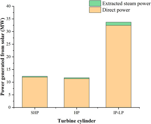
FIGURE 9. Distribution of power generated from solar in the turbine cylinder under 75% THA load.
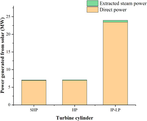
FIGURE 10. Distribution of power generated from solar in the turbine cylinder under 50% THA load.
Exergy destruction distribution
Figure 11 shows the exergy destruction of the TSACPG system at the maximum steam extraction situation under the loads of 100%, 75%, and 50% THA. Under these three loads, the boiler exergy destructions are 511.55, 398.75, and 285.17 MW, respectively. The boiler accounts for the largest proportion of the total exergy destruction of the system under various loads. The reason is that the chemical reaction of coal combustion in the boiler furnace will result in a mass of irreversible losses. The extreme difference in temperature between the working fluid and the flue gas during the heat transfer process and the phase change of working fluid also occur in the boiler. Then, the solar field is the second largest exergy destruction component of the TSACPG system. In this study, when the solar side parameters of the TSACPG system are fixed, the exergy destruction of the solar field will increase with the decrease of the load. Specifically, the exergy destructions of the solar field are 163.22, 199.22, and 234.12 MW in 100% THA, 75% THA, and 50% THA, respectively. With the decrease of the load, the utilized solar exergy that can enter the unit decreases and the loss increases accordingly.
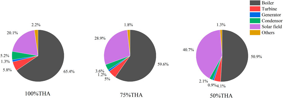
FIGURE 11. Exergy destruction distributions of the TSACPG system under 100% THA, 75% THA, and 50% THA load.
According to the solar contribution evaluation approach based on the exergy cumulative calculation proposed in this study, a small amount of solar exergy destruction in the turbine will mainly affect the calculation results of power generated from the solar. Figures 12–14 show the distribution of solar exergy destruction imported from different integration positions in different cylinders under different loads. It can be seen that the solar exergy imported into the feedwater has destruction in the SHP, HP, and IP–LP, and there is relatively more exergy destruction in the IP–LP. The solar exergy imported into the first reheat steam only has destruction in the HP and IP–LP because in this part, solar exergy does not flow into the SHP. For the same reason, the solar exergy imported into the second reheat steam only has destruction in IP–LP. Specifically, under 100% THA load, the solar exergy destructions are 1.09, 0.89, and 4.61 MW in SHP, HP, and IP–LP, respectively. Under the 75% THA load, the solar exergy destructions are 0.79, 0.64, and 3.30 MW in the SHP, HP, and IP–LP, respectively. Under the 50% THA load, the solar exergy destructions are 0.46, 0.39, and 2.20 MW in SHP, HP, and IP–LP, respectively.
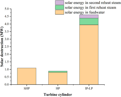
FIGURE 12. Solar exergy destruction in the turbine cylinder under 100% THA load.
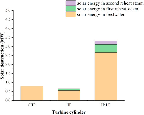
FIGURE 13. Solar exergy destruction in the turbine cylinder under 75% THA load.
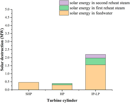
FIGURE 14. Solar exergy destruction in the turbine cylinder under 50% THA load.
Conclusion
In this study, a novel solar contribution evaluation method of the TSACPG system based on the exergy cumulative calculation method is proposed. On the basis of the second law of thermodynamics, this method distinguishes the difference between the solar exergy and coal exergy. For the solar-aided coal-fired power generation system with multiple integration positions where solar energy is input, the impact on the difference of the input position has been considered, and the contributions of solar from different integration position input are analyzed and calculated separately. Finally, the ultimate evaluation results are obtained by cumulative calculation. When the evaluation method is applied in the TSACPG system with TES proposed in this study, the comparison analysis with other evaluation methods is carried out and the comprehensiveness and accuracy of this method are revealed in detail. The following conclusions can be drawn:
1) The evaluation method of solar energy contribution based on “energy quantity” ignores the energy grade between solar and coal and overestimates the solar energy contribution. When methods I and II are applied to the TSACPG system under 100% THA load proposed in this study, the results are 120.89 and 109.209 MW. They overestimate the solar contributions that are 20.37% and 8.80% compared with method IV proposed in this study.
2) Method III ignores the differences caused by the different integration positions of solar energy input into coal-fired units and the differences between the positions of solar exergy destruction and coal exergy destruction. The result of method III is 61.890 MW. Compared with method IV, method III underestimates the solar contribution that is 62.28% under 100% THA load of the TSACPG system in this study.
3) In the TSACPG system, both the boiler exergy destruction and solar field exergy destruction under different loads account for the main part of the whole system exergy destruction. They account for 85.6%, 88.6%, and 91.8% under 100% THA, 75% THA, and 50% THA loads, respectively. Solar exergy destruction in turbine input from different integration positions shows significant differences. Although the contribution of solar energy that enters the feedwater is relatively larger, the exergy destruction of that will be larger. The solar exergy destructions from feedwater in the turbine are 5.84, 3.99, and 2.32 MW under 100% THA, 75% THA and 50% THA loads, respectively.
Data availability statement
The original contributions presented in the study are included in the article/Supplementary Material; further inquiries can be directed to the corresponding author.
Author contributions
YJ: conceptualization, investigation, methodology, programming, writing—original draft, and writing—review and editing. LD: supervision, funding acquisition, conceptualization, and writing—review and editing. YT: data curation and software. MY: validation and simulation. LP: conceptualization and writing—review and editing.
Funding
This study has been supported by the Science Fund for Creative Research Groups of the National Natural Science Foundation of China (No. 51821004) and the Major Program of the National Natural Science Foundation of China (No.52090064).
Conflict of interest
The authors declare that the research was conducted in the absence of any commercial or financial relationships that could be construed as a potential conflict of interest.
Publisher’s note
All claims expressed in this article are solely those of the authors and do not necessarily represent those of their affiliated organizations, or those of the publisher, the editors, and the reviewers. Any product that may be evaluated in this article, or claim that may be made by its manufacturer, is not guaranteed or endorsed by the publisher.
References
Agarwal, N., Raj, M., and Bhattacharya, J. (2020). Solar tower on an uneven terrain: Methodology and case study. Renew. Energy 161, 543–558. doi:10.1016/j.renene.2020.07.113
Ding, S., Zhang, M., and Song, Y. (2019). Exploring China's carbon emissions peak for different carbon tax scenarios. Energy Policy 129, 1245–1252. doi:10.1016/j.enpol.2019.03.037
Duan, L., Yu, X., Jia, S., Wang, B., and Zhang, J. (2017). Performance analysis of a tower solar collector‐aided coal‐fired power generation system. Energy Sci. Eng. 5 (1), 38–50. doi:10.1002/ese3.147
Hong, H., Peng, S., Zhang, H., Sun, J., and Jin, H. (2017). Performance assessment of hybrid solar energy and coal-fired power plant based on feed-water preheating. Energy 128, 830–838. doi:10.1016/j.energy.2017.04.050
Hou, H., Wu, J., Yang, Y., Hu, E., and Chen, S. (2015). Performance of a solar aided power plant in fuel saving mode. Appl. Energy 160, 873–881. doi:10.1016/j.apenergy.2015.01.092
Hou, H., Xu, Z., and Yang, Y. (2016). An evaluation method of solar contribution in a solar aided power generation (SAPG) system based on exergy analysis. Appl. Energy 182, 1–8. doi:10.1016/j.apenergy.2016.08.109
Huang, C., Hou, H., Hu, E., Yu, G., Chen, S., and Yang, Y. (2020). Measures to reduce solar energy dumped in a solar aided power generation plant. Appl. Energy 258, 114106. doi:10.1016/j.apenergy.2019.114106
Jiang, Y., Duan, L., Pang, L., and Song, J. (2021). Thermal performance study of tower solar aided double reheat coal-fired power generation system. Energy 230, 120857. doi:10.1016/j.energy.2021.120857
Jiang, Y., Duan, L., Yang, M., Tong, Y., and Pang, L. (2022). Performance analysis of tower solar aided coal-fired power plant with thermal energy storage. Appl. Therm. Eng. 206, 118101. doi:10.1016/j.applthermaleng.2022.118101
Li, C., Yang, Z., Zhai, R., Yang, Y., Patchigolla, K., and Oakey, J. E. (2018). Off-design thermodynamic performances of a solar tower aided coal-fired power plant for different solar multiples with thermal energy storage. Energy 163, 956–968. doi:10.1016/j.energy.2018.08.186
Li, C., Zhai, R., Yang, Y., Patchigolla, K., and Oakey, J. E. (2018). Thermal performance of different integration schemes for a solar tower aided coal-fired power system. Energy Convers. Manag. 171, 1237–1245. doi:10.1016/j.enconman.2018.06.064
Li, Y., Zhou, L., Xu, G., Fang, Y., Zhao, S., and Yang, Y. (2014). Thermodynamic analysis and optimization of a double reheat system in an ultra-supercritical power plant. Energy 74, 202–214. doi:10.1016/j.energy.2014.05.057
Liu, H., Zhai, R., Patchigolla, K., Turner, P., and Yang, Y. (2020). Performance analysis of a novel combined solar trough and tower aided coal-fired power generation system. Energy 201, 117597. doi:10.1016/j.energy.2020.117597
Manzolini, G., Lucca, G., Binotti, M., and Lozza, G. (2021). A two-step procedure for the selection of innovative high temperature heat transfer fluids in solar tower power plants. Renew. Energy 177, 807–822. doi:10.1016/j.renene.2021.05.153
Petela, R. (2003). Exergy of undiluted thermal radiation. Sol. Energy 74 (6), 469–488. doi:10.1016/s0038-092x(03)00226-3
Qin, J., Hu, E., and Li, X. (2020). Solar aided power generation: A review. Energy Built Environ. 1 (1), 11–26. doi:10.1016/j.enbenv.2019.09.003
Qin, J., Hu, E., Nathan, G. J., and Chen, L. (2017). Concentrating or non-concentrating solar collectors for solar Aided Power Generation? Energy Convers. Manag. 152, 281–290. doi:10.1016/j.enconman.2017.09.054
Qin, J., and Hu, E. (2017). The impact of solar radiation on the annual net solar to power efficiency of a Solar Aided Power Generation plant with twelve possible “configuration-operation” combinations. Energy Procedia 105, 149–154. doi:10.1016/j.egypro.2017.03.294
Rushdi, M. A., Yoshida, S., Watanabe, K., and Ohya, Y. (2021). Machine learning approaches for thermal updraft prediction in wind solar tower systems. Renew. Energy 177, 1001–1013. doi:10.1016/j.renene.2021.06.033
Soares, J., Oliveira, A. C., and Valenzuela, L. (2021). A dynamic model for once-through direct steam generation in linear focus solar collectors. Renew. Energy 163, 246–261. doi:10.1016/j.renene.2020.08.127
Świerzewski, M., Kalina, J., and Musiał, A. (2021). Techno-economic optimization of ORC system structure, size and working fluid within biomass-fired municipal cogeneration plant retrofitting project. Renew. Energy 180, 281–296. doi:10.1016/j.renene.2021.08.068
Wang, G., Dong, B., and Chen, Z. (2021). Design and behaviour estimate of a novel concentrated solar-driven power and desalination system using S–CO2 Brayton cycle and MSF technology. Renew. Energy 176, 555–564. doi:10.1016/j.renene.2021.05.091
Wang, J., Duan, L., Yang, Y., and Pang, L. (2019). Multi‐objective optimization of solar‐aided coal‐fired power generation system under off‐design work conditions. Energy Sci. Eng. 7 (2), 379–398. doi:10.1002/ese3.280
Wang, J., Duan, L., Yang, Y., and Yang, Z. (2019). Study on the general system integration optimization method of the solar aided coal-fired power generation system. Energy 169, 660–673. doi:10.1016/j.energy.2018.12.054
Wu, J., Hou, H., and Yang, Y. (2016). The optimization of integration modes in solar aided power generation (SAPG) system. Energy Convers. Manag. 126, 774–789. doi:10.1016/j.enconman.2016.08.051
Xin, T., Xu, C., and Yang, Y. (2020). A general and simple method for evaluating the performance of the modified steam Rankine cycle: Thermal cycle splitting analytical method. Energy Convers. Manag. 210, 112712. doi:10.1016/j.enconman.2020.112712
Xu, C., Wang, Z., Li, X., and Sun, F. (2011). Energy and exergy analysis of solar power tower plants. Appl. Therm. Eng. 31 (17-18), 3904–3913. doi:10.1016/j.applthermaleng.2011.07.038
Yan, Q., Yang, Y., Nishimura, A., Kouzani, A., and Hu, E. (2010). Multi-point and multi-level solar integration into a conventional coal-fired power plant. Energy fuels. 24 (7), 3733–3738. doi:10.1021/ef9012906
Yang, Y., Wang, L., Dong, C., Xu, G., Morosuk, T., and Tsatsaronis, G. (2013). Comprehensive exergy-based evaluation and parametric study of a coal-fired ultra-supercritical power plant. Appl. energy 112, 1087–1099. doi:10.1016/j.apenergy.2012.12.063
Yang, Y., Yan, Q., Zhai, R., Kouzani, A., and Hu, E. (2011). An efficient way to use medium-or-low temperature solar heat for power generation–integration into conventional power plant. Appl. Therm. Eng. 31 (2-3), 157–162. doi:10.1016/j.applthermaleng.2010.08.024
Zhang, M., Du, X., Pang, L., Xu, C., and Yang, L. (2016). Performance of double source boiler with coal-fired and solar power tower heat for supercritical power generating unit. Energy 104, 64–75. doi:10.1016/j.energy.2016.03.111
Zhang, M., Xu, C., Du, X., Amjad, M., and Wen, D. (2017). Off-design performance of concentrated solar heat and coal double-source boiler power generation with thermocline energy storage. Appl. Energy 189, 697–710. doi:10.1016/j.apenergy.2016.12.095
Zhang, N., Hou, H., Yu, G., Hu, E., Duan, L., and Zhao, J. (2019). Simulated performance analysis of a solar aided power generation plant in fuel saving operation mode. Energy 166, 918–928. doi:10.1016/j.energy.2018.10.014
Zhao, Y., Hong, H., and Jin, H. (2014). Evaluation criteria for enhanced solar–coal hybrid power plant performance. Appl. Therm. Eng. 73 (1), 577–587. doi:10.1016/j.applthermaleng.2014.08.003
Zhu, Y., Pei, J., Cao, C., Zhai, R., Yang, Y., Reyes-Belmonte, M., et al. (2018). Optimization of solar aided coal-fired power plant layouts using multi-criteria assessment. Appl. Therm. Eng. 137, 406–418. doi:10.1016/j.applthermaleng.2018.03.093
Zhu, Y., Zhai, R., Peng, H., and Yang, Y. (2016). Exergy destruction analysis of solar tower aided coal-fired power generation system using exergy and advanced exergetic methods. Appl. Therm. Eng. 108, 339–346. doi:10.1016/j.applthermaleng.2016.07.116
Zhu, Y., Zhai, R., Qi, J., Yang, Y., Reyes-Belmonte, M., Romero, M., et al. (2017). Annual performance of solar tower aided coal-fired power generation system. Energy 119, 662–674. doi:10.1016/j.energy.2016.11.023
Nomenclature
Abbreviations
CON condenser
DEA deaerator
DNI direct normal irradiance, W/m2
GEN generator
HP high-pressure cylinder
HPR high-pressure regenerator
IP-LP intermediate-pressure and low-pressure cylinder
LPR low-pressure regenerator
MSHE molten salt heat exchanger
OSC out-steam cooler
RH-1 first reheat part in the boiler
RH-2 second reheat part in the boiler
SH superheat part in the boiler
SHP super-high-pressure cylinder
TES thermal energy storage
Mathematical symbols
h enthalpy of working medium in a specific state, kJ/kg
Greek symbols
Keywords: solar-aided coal-fired power generation, solar contribution, evaluation method, exergy, cumulative calculation
Citation: Jiang Y, Duan L, Tong Y, Yang M and Pang L (2022) A study on a novel solar contribution evaluation method for the solar-aided coal-fired power generation system. Front. Energy Res. 10:1026953. doi: 10.3389/fenrg.2022.1026953
Received: 24 August 2022; Accepted: 17 October 2022;
Published: 03 November 2022.
Edited by:
Covadonga Pevida, Spanish National Research Council (CSIC), SpainReviewed by:
Rongyue Sun, Nanjing Institute of Technology (NJIT), ChinaShaopeng Guo, Xi’an University of Architecture and Technology, China
Copyright © 2022 Jiang, Duan, Tong, Yang and Pang. This is an open-access article distributed under the terms of the Creative Commons Attribution License (CC BY). The use, distribution or reproduction in other forums is permitted, provided the original author(s) and the copyright owner(s) are credited and that the original publication in this journal is cited, in accordance with accepted academic practice. No use, distribution or reproduction is permitted which does not comply with these terms.
*Correspondence: Liqiang Duan, ZGxxQG5jZXB1LmVkdS5jbg==