 K. Selvakumar1
 R. Palanisamy
 Ali Selim
 Hossam Kotb
 Mohit Bajaj
 Salah Kamel
- 1Department of EEE, SRM Institute of Science and Technology, Kattankulathur, India
- 2Department of EEE, Shree Sathyam College of Engineering and Technology, Salem, India
- 3Department of CSE, Shree Sathyam College of Engineering and Technology, Salem, India
- 4Electrical Engineering Department, Faculty of Engineering, Aswan University, Aswan, Egypt
- 5Department of Electrical Power and Machines, Faculty of Engineering, Alexandria University, Alexandria, Egypt
- 6Department of Electrical Engineering, Graphic Era (Deemed to be University), Dehradun, India
In this article, a seven-level triple-time voltage-boosting topology (8S7L-TTB) is proposed, which has eight switches as the minimum. This topology is used as DSTATCOM to eliminate power-quality issues. In a three-phase four-wire distribution system, specific unpredictable issues have emerged through the increase of unbalanced linear and non-linear loads, which has caused various drawbacks such as voltage imbalance, poor voltage regulation, increased reactive components, and harmonics generation, through which the life period of the system has been minimized, undesirable heating has been produced, and the RMS voltage has been reduced. Hence, it is highly essential to eliminate the issues as mentioned earlier. In this research, a PV-based DSTATCOM is introduced for online-monitoring adaptive Chebyshev neural network controller with triple-boost inverter topology. The three-phase system’s D-Q components, which have been continuously extracted under instant-loading conditions, and the reference magnitude, have been compared through the proposed controller. The error signal is received from the adaptive Chebyshev neural network controller, through which the proposed inverter-switching devices are triggered with multi-carrier pulse width-modulation technique are used to compute the THD of 2.79%. Furthermore, this proposed seven-level inverter and controller have solved the aforementioned problems and maintained the floating capacitor’s voltage nearly as similar as the source voltage in different loading conditions to ensure the efficiency of the system is at 96.82%. To ensure its suitability in real-time, the proposed controller is simulated with MATLAB software and validated through the downscale experimental setup and the results are observed.
Introduction
Due to the proliferating power demand of consumers, the necessity of a distribution system is rapidly increasing. Due to the increase of non-linear loads, the existing distribution systems have issues such as extreme reactive power, low power factor, poor voltage regulation, high neutral current, and high THD (Mahdianpoor et al., 2011; Bajaj et al., 2015). Since the traditional load compensation technique has provided the fixed load conditions, it is not suitable for applications with dynamic- and transient-loading conditions (Rahmani et al., 2011). To overcome this issue, several power devices such as DVR, STATCOM, and UPQC have been utilized in recent days for load compensation. The DVR is the series-connected device and provides the desired voltage magnitude. Similarly, the shunt-connected STATCOM device has injected the current magnitude and the UPQC is generally a shunt and series-connected device (Bajaj, 2020).
Among all the devices mentioned previously, the DSTATCOM has provided effective load compensation in the distribution system, which assists in solving various power-quality issues. When the linear and non-linear loads are increased, the current magnitude becomes high and a low power factor is produced. In this condition, the DSTATCOM is used to mitigate the current-based issues (Singh et al., 2014). Recently, multilevel inverters are used as a DSTATCOM to rectify the issues as mentioned earlier. The MLI technologies have significant innate merits over the conventional inverter, including N number of levels with minimum switches, good quality of power, less electromagnetic interference, low losses, easy controllability, and fewer control circuits (Choudhury et al., 2021). The conventional three-level inverter fails to provide good power quality in generating low THD and voltage stress.
To enhance these necessities, multilevel inverters have been utilized and improved (Srikanthan et al., 2009). The main objective of the DSTATCOM is to maintain the sinusoidal waveform with all three phases’ displacement of 120°. Recently, the distribution system’s online monitoring is a suitable control technique to maintain a balanced system without any power quality issues. This type of controller has special qualities in quick response during the transient state, providing good accuracy and compatibility. Some existing notable multilevel inverters such as flying capacitor-based inverter, diode-clamped-based MLI, T-Type inverter, and four-level inverter have been utilized as DSTATCOMs, which are shown in Figure 1 (Shukla, 2005). A five-level FCMLI is proposed in the SMIB system to give a combined compensation through the appropriate allotment of the capacitor’s charging and discharging times. This topology is highly expensive since it has more DC sources and parts. The DCMLI and FCMLI are utilized to enhance the system by using the linear quadratic controller as state-feedback control.
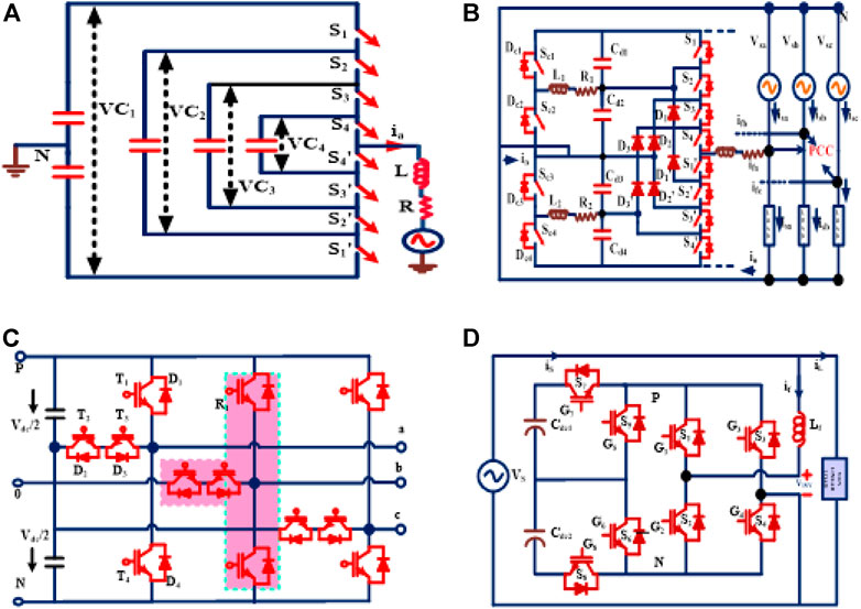
FIGURE 1. Existing DSTATCOM with different multilevel inverter topologies (A) presented in (Shukla, 2007a), (B) presented in (Shukla, 2008), (C) presented (Palanisamy and Vijayakumar, 2022), and (D) simplified four-level inverter topology.
The maximum compensation is provided with a voltage level of ±Vdc/2, which is not exactly the source voltage (Shukla, 2007a). In paper (Mishra and Karthikeyan, 2009), the H Bridge VSI topology-based DSTATCOM is coupled in a 3-phase 4-wire system to provide the required compensation during the transient load-up conditions. This is accomplished by utilizing a quick-acting DC voltage regulator. (Nijhawan et al., 2013). DSTATCOM has used multiple switches, an isolation transformer, three storage capacitors, and an interface inductor. The DC link capacitors have an essential function called compensator operation.
Owing to the increase of induction furnace load, a considerable THD level is generated in the power-system network, which has been overcome by implementing the carrier-based PWM technique with a five-level inverter. A smart control technique is provided in the two-level DSTATCOM-integrated PV system, which has supplied the power to the load and improved the power quality (Singh et al., 2018). A novel control circuit is proposed for equalizing the capacitor voltage (Shukla, 2008). The fluctuation of capacitor voltage is the inherent issue in diode-clamped multilevel inverter (DCMLI)(Palanisamy and Vijayakumar, 2022). In low-voltage applications, three-level T-type converters are used. The performance is analyzed by evaluating the efficiency when operating with high-switching frequency. Various MPPT techniques are employed to connect the PV panel with VSI circuits. A new methodology is proposed to optimize the dc-link voltage based on the system’s voltage requirements (Bajaj and Rana, 2018). The HCC controls the switching pulses. The ANN algorithm-based Chebyshev function has provided the shunt compensation in the 3-phase 4-wire system. To compensate for the neutral current, three single-phase transformers are used (Bajaj et al., 2021).
This type of DSTATCOM comprises of two stages for generating a four-level output voltage through which the switching loss and computational burden have been reduced. Three levels of voltage were generated from the first stage and zero voltage from the second stage. The generated voltage was the same as the source voltage (Ye et al., 2020).
Hysteresis current control plays a key role in providing load compensation by utilizing a five-level FCMLI (Shukla, 2007b). The reference current is tracked by the controller, which leads to the occurrence of tracking errors, and to this, three-band levels are applied. To improve the PCC’s power quality, (Myneni and Siva Kumar, 2019), an LCL filter is used and operated in both modes (CCM and VCM) (Palanisamy and Vijayakumar, 2020). To mitigate the harmonics and provide the neutral current compensation in the current control mode, the PCC voltage must be in the load-operating range. Thus, an adaptive control algorithm is applied to eliminate these issues.
To provide a suitable compensation under different loading conditions, a predictive-based current controller (Palanisamy and Vijayakumar, 2020) is used along with DSTATCOM. The predicted values of the reference current are compared with the actual magnitudes by using appropriate sensors. The control action takes place based on the error signal. For a quick response, a dynamic and fast DSP processor is required with huge storage memory. The appropriate switching states have been obtained by selecting a cost function, whereas the square of error among the actual and reference currents in DSTATCOM has been lowered. The viability and desirability of the suggested method have been proved through simulations and FPGA-based experimentation. All the power-quality issues in the grid system have been solved by using an adaptive real power with the current (icosϕ) control technique (Mangaraj et al., 2020). A zigzag transformer-based DSTATCOM (Badoni et al., 2020) is used along with the adaptive controller-based Euclidean direction search technique (Patel et al., 2020) to mitigate the power-quality issues. The DSTATCOM inverter is controlled by a PV system as a combination of active mode–active current control with a feed-forward control loop to provide various compensations to the grid system. The non-linearity issues arise between the grid and the PV system.
In this article, the nine-switch seven-level triple-times voltage boost topology (8S7L-TTB) is proposed as the DSTATCOM. In the conventional inverter-based distributed compensation system, the obtained alternating voltage is smaller than the DC link voltage (VDC), leading to unexpected harmonics in the source current. To avoid such issues, the proposed seven-level voltage is generated with boosting capability, which requires no additional components, and because of this quality, the usage of the boost converter is omitted. To provide a fast and dynamic compensation of the proposed 8STTBML inverter, an adaptive back-stepping Chebyshev neural network controller is used in this study, through which the system magnitudes have been monitored and controlled. This controller has achieved all the mentioned advantages.
The proposed research contains the following merits,
1. A minimum of nine switches is enough for the generation of seven-level output voltage.
2. The floating capacitor voltage is almost constant as the source voltage because the charging duration is higher than the discharging time as depicted in Table 1.
3. The floating capacitor voltage has a self-balancing capability.
4. The online controller provides good performance in the dynamics of load changes with steady and transient conditions.
5. The controller makes the system asymptotically stable through the Lyapunov Stability analysis during the whole operation.
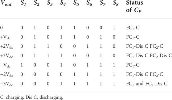
TABLE 1. Switching sequence for the proposed 8S7L-TTB topology.
(2) Vo = ±Vdc: In this mode, the capacitor is charging while turning ON the switches S4 and S5. After the completion of this mode, the floating capacitor (FC1) can deliver the most extreme voltage range of 2Vdc. The ± Vdc voltage is spilling out from the DC source to the load terminal by turning on at least two switches. S2 and S7 are turned ON for the positive half-cycle. S1 and S8 are turned ON for the negative half-cycle as depicted in Figures 4A,E.
(3) VO = ±2Vdc: Along with the source voltage (Vdc), the floating capacitor FC1 (Vdc) is released to the load by triggering the switches S3, S7, and S2 for a positive cycle. Similarly, S1, S3, and S8 are triggered for a negative cycle, which has been portrayed in Figures 4B,F. The FC2 capacitor is charged by closing the switch S6.
(4) VO = ±3 Vdc: In this mode, the charged floating capacitors FC1 (Vdc) and FC2 (Vdc) are discharged in consideration with the source voltage (Vdc). The acquired load voltage is 3 Vdc. To get a positive load voltage of + 3Vdc, the accompanying switches S3 and S7 and S2 and S4 are turned ON. For −3Vdc, the S3 and S4 switches are triggered along with the polarity-changer switches, which have been portrayed in Figures 4C, G.
Proposed control methodology in a three-phase four-wire system
In this research, the PV-based DSTATCOM inverter is coupled with the 3-phase 4-wire system through an adaptive online-monitoring controller as shown in Figure 2. In this circuit, the proposed 8S7L-TTB inverter is connected to the PV source through the PCC. All the three-phases of the linear and non-linear load magnitudes are tracked by the portion of online weight-update law.
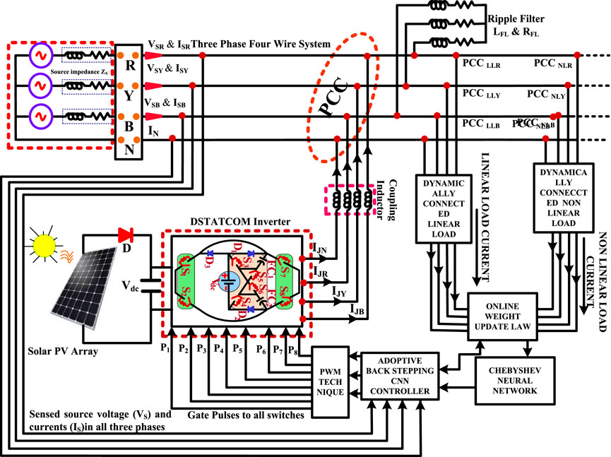
FIGURE 2. Proposed inverter topology with the overall structure of the three-phase four-wire system of the DSTATCOM application.
The three-phase system’s D–Q components are continuously extracted from the source magnitudes and compared to the instant-loading magnitudes. The switching pulses are triggered with an approximate modulation index through the PWM technique based on the error signal. The required compensation magnitudes are injected to the PCC point from the 8STTB VSI through the coupling inductor. Ripple filter (RFL and CFL) is connected to the system to remove the switching pulses.
Execution of the proposed control scheme with 8S7L-TTB inverter topology
An integrating PV-based seven-level inverter with triple-times voltage-boosting topology is proposed in Figure 3. It has eight switches (S1–S8), diodes (D1 and D2), and a DC voltage source (Vdc), load voltage (Vo), and two floating capacitors (FC1, FC2). This inverter comprises two sections called the voltage-boosting section and polarity-changer circuit.
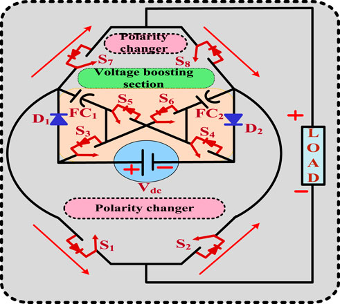
FIGURE 3. Proposed triple-times voltage-boosting inverter topology (8S7L-TTB).
The first section comprises of four switches (S3, S4, S5, and S6) with two diodes (D1 and D2) and two floating capacitors (FC1 and FC2) to generate different voltage levels (vdc, 2vdc, and 3vdc). The second section has used four switches (S1, S2, S7, and S8) as the load-polarity changers. During the diversity-loading condition, the capacitor voltage must maintain the sustainable value (Vdc) without any voltage-stability issues. The floating capacitor value is chosen as high. The switches (S3, S6 and S4, S5) are coupled with the source voltage during the floating capacitors’ charging time. The capacitors are connected in series with the source voltage through the switches (S3 and S4) to ensure the self-balancing capability of FCs during discharging.
Description in modes of operation
The seven-level switching states of the current flow are described in this section. Figures 4A–G have depicted the detailed analysis of the positive and negative paths of current flow. The switching states, charging, and discharging states of the capacitor are shown in Table 1. The full cycle includes positive, negative, and zero states. The 0 and 1 represent the switching states, where 1 indicates the ON state of the switches and 0 represents the switches’ OFF state.
(1) Vo = 0: In the polarity changer’s load terminal, the zero-circulating current is produced by turning ON the switches S2 and S8, and during this period, the floating capacitor FC1 is charging through the conducting switches of S4 and S5. Thus, every capacitor’s charging extent is Vdc. In Figure 4A, the charging path is highlighted through the shaded area.

FIGURE 4. (A–G): A 7 level of inverter voltage of the proposed 8S-TTB-MLI topology.
Adoptive back-stepping Chebyshev neural network controller
Generally, the performance of neural networks is enhanced by including several hidden layers which need bulk computation. These computational burdens that arise because of the hidden layers are eliminated by Chebyshev polynomials (ChP) which are utilized for the uniform approximation of other functions and attain the solution for differential equation-least-square approximation.
Expansion of Chebyshev polynomial
The differential equation for Chebyshev is given in Eq. 1, and the solution is attained in terms of (ChP).
The singular points for the Chebyshev differential equation are at −1, 1, and ∞ for x <
The aforementioned Eq. 3 is rewritten by adjusting the limits as,
Eq. 4 is modified after differentiation and given as,
Eq. 1 is rewritten as,
Eq. 7 is expanded and given as,
After simplification,
Eq. 10 is a generalized recurrence equation. The even coefficients for i = 0, 2…. are given as,
The generalized pattern for even and odd coefficients are given as,
Eq. 1 is resolved using Eqs 13, 14, and 2 and the solution is given as,
The aforementioned equation is rewritten as,
Eqs 17, 18 are the equivalent form of Eq. 16.
Here the first kind and second kind Chebyshev polynomials are denoted as
Where
By analyzing the aforementioned pattern, the recursive relation is stated as
Where—
Thus, by ChP, the hidden layers in the neural networks are eliminated, minimizing the computational time to become more efficient (Singh et al., 2018).
Chebyshev neural network controller for generating the gating sequence for DSTATCOM
The reference current is generated from the ChNN controller and the gating sequence for the DSTATCOM is generated by the multi-carrier PWM technique. Here, a back propagation algorithm is utilized for training the weights of ChNN. An illustration for generating the gating sequence by the ChNN controller is given in Figure 6.
The load current of R-phase is processed by ChP, which gives the approximations as Z1, Z2, and Z3. These approximations are multiplied by the weight of the neural network WR1 to obtain the Chebyshev expansion as ZR1. Likewise, the similar components ZR2, ZR3 are also obtained. All these three components are added and then managed by tanh. Thus, a back-propagation algorithm attains the output OR (k) with the estimation of reference output OR (k)’. The weights WR1, WR2, and WR3 are updated based on Eq. 21.
Here, the constant learning rate is denoted by
The reference current for all the three phases obtained from the ChNN controller is analogized with the actual values of the three-phase currents and the gating sequence is accordingly generated by the multi-carrier PWM technique. As the DSTATCOM operates in high frequency, the switching loss is inherent. A power-loss component (Oloss) is calculated by analogizing the actual and reference values of Vdc in a PI controller.
KP and Kl denote the proportional and integral constants, the reference and actual values of link voltage are denoted by Vdc and V*dc. The error signal is given as,
The final weight Oeff is obtained by adding Oloss and Oavg
The instantaneous values of the three-phase PCC voltage (VtR, VtY, and VtB) are sensed and its peak magnitude is evaluated as,
The reference currents for the three phases are computed as,
The phase unit templates are computed as,
Thus, the actual and reference values of the source current are analogized and fed to the multi-carrier PWM technique to generate the required gating sequence for the nine switches of the proposed inverter.
Determination of the capacitor’s value
The longest discharge time (LDT) for one full cycle of the fundamental output voltage, Vab is shown in Figure 5, which is considered to find the switched C1 and C2 capacitors’ optimal value.
FIGURE 5. Flowchart for Chebyshev polynomial.
The energy released by the switched capacitor C during LDT is computed by
The switched capacitor’s C3, optimal value can be decided by
Multi-carrier PWM technique
Multi carrier PWM (MCPWM) generates the switching pattern for the proposed inverter and the reason for choosing this PWM technique is its simplicity and ease of implementation. The reference source currents generated by the ChNN controller and the carrier signal are analogized to control the inverter’s switches. Which is shown in Figure 7.
The amplitude modulation-index (ma) is given as the ratio of the peak-to-peak amplitude of the reference-modulating signal (Aref) to that of the carrier signal (Ac) which is given as,
The frequency modulation-index (mf) is given as the ratio of the frequency of the carrier signal (fc) to that of the reference-modulating signal (fr) which is given as,
The illustration of MCPWM is in Figure 6 in which two triangular carrier signals are analogized with a reference sinusoidal signal.
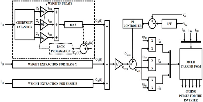
FIGURE 6. Illustration of the ChNN controller.
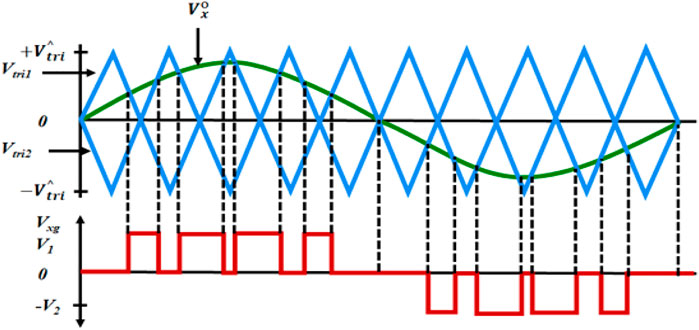
FIGURE 7. MCPWM technique.
Result and discussions
The power-quality issues are exterminated through the implementation of 8S7L-TTB topology as the DSTATCOM, through which the fluctuations in the linear and non-linear loads of a 3-phase 4-wire distribution system have been eliminated.
The D–Q components of a 3-phase system are persistently extracted through the PV-based DSTATCOM with online-monitoring-adaptive ChNN controller, through which the switching devices of the inverter are triggered with the aid of the multicarrier PWM technique. The system has been simulated in MATLAB software and the results were observed. The DSTATCOM employed here is PV-based and Figure 8 highlights the voltage and the current representations of PV. The PV panel’s temperature is in the range of 25°C to 40°C irradiance 1,000 W/m2. The output voltage representation of the proposed 7L inverter topology is highlighted in Figure 9. The Figure 10 shows the representation of load voltage and load current.
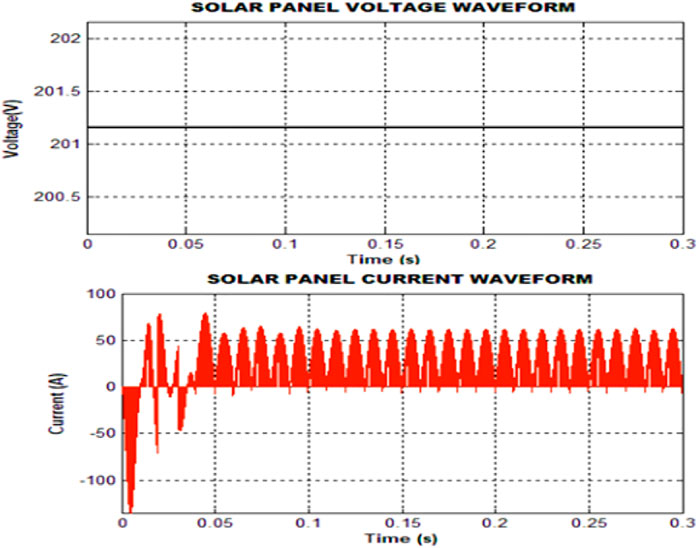
FIGURE 8. Parameters of the solar panel.
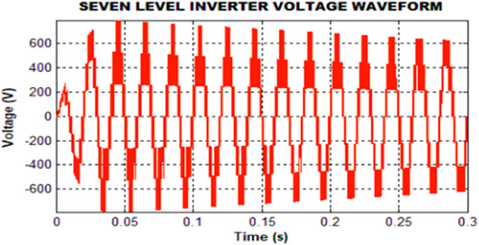
FIGURE 9. Voltage representation of the proposed 8S7L-TTB topology.
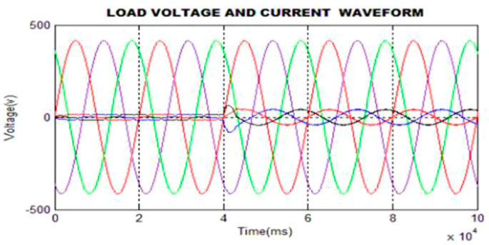
FIGURE 10. Representation of load voltage and load current.
The opposite harmonics are to be introduced in the PCC and the ChNN controller helps in generating the reference source current. The gating sequence for the 7L inverter is generated through MCPWM. The load voltage and load current illustrations are revealed in Figure 9, and using the ChNN controller, the THD is minimized to 2.79% as shown in Figure 11.
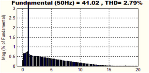
FIGURE 11. Source current THD using the ChNN controller.
Hardware implementation
The proposed PV-based DSTATCOM with a seven-level inverter is instigated using FPGA SPARTAN 6E in hardware. A ChNN controller eliminates the need for the MCPWM technique that generates the harmonics and the pulses for the inverter.
The output of the PV module is illustrated in Figure 12. Initially, there exist oscillations in the PV system and after a certain period, the waveform appears without oscillations.
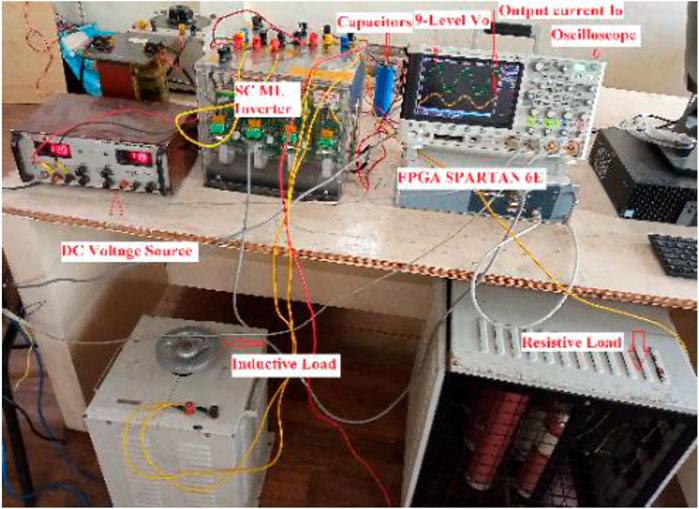
FIGURE 12. Experimental setup for the seven-level DSTATCOM.
The output voltage depiction of the proposed 8S-7L inverter is illustrated in Figure 13 which reveals that three levels are on the positive side and three levels are on the negative side with a one–zero level.
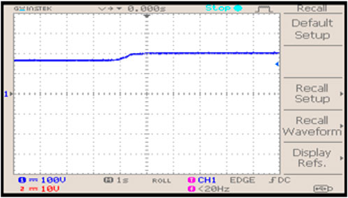
FIGURE 13. Voltage representation of the PV system.
The voltage and current illustrations of the 3-phase 4-wire system are shown in Figure 14 and Figure 15 respectively. Initially, in the PV module, there will be oscillations and after the instigation of the proposed ChNN controller, the current harmonics are eliminated and so the waveform remains sinusoidal in nature.
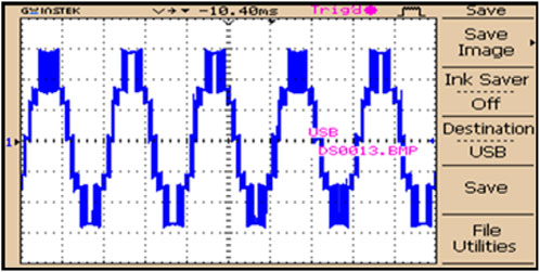
FIGURE 14. Output voltage representation of an 8S7L- TTB inverter.
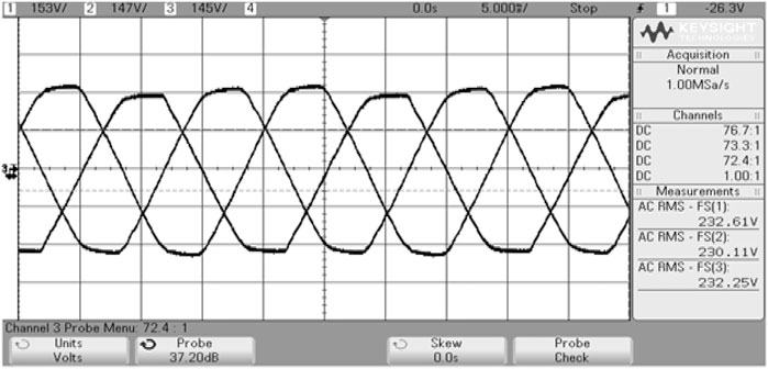
FIGURE 15. Three-phase voltage.
The 3Ф voltage and current waveforms as observed are illustrated in Figure 16 which reveal that the voltage and current are in phase with a UPF.
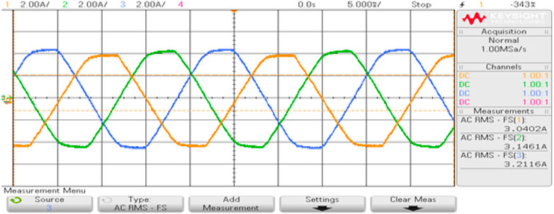
FIGURE 16. Three-phase current.
The comparison of source current THD is illustrated in Figure 17. It is noted that the THD of 2.79% is accomplished by the ChNN controller which reveals the proposed controller’s superiority. The Figure 18 shows the THD comparsion for various PWM methods. The proposed topology’s voltage generation is high when compared to existing topologies with least-switching devices for a 3- phase four-wire system. The losses for the proposed inverter are computed by using the PLECS software for determining the efficiency of the inverter. The Figure 19 shows the switching losses for the proposed system.
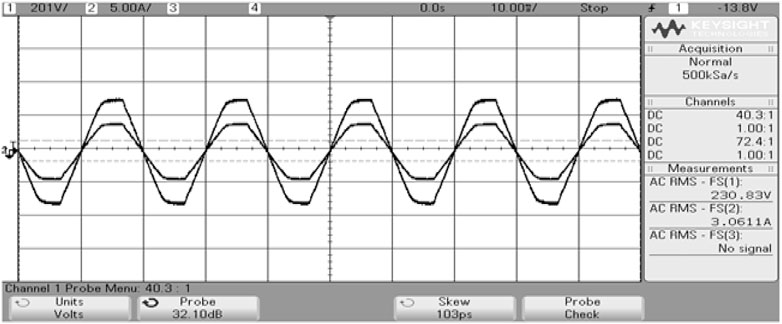
FIGURE 17. Three-phase voltage and current.
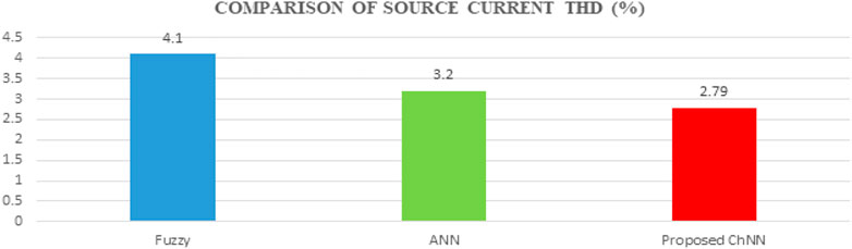
FIGURE 18. THD comparison.
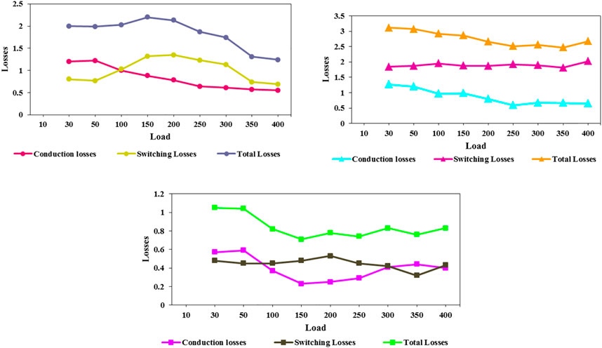
FIGURE 19. Switching losses for the proposed inverter.
Conclusion
The present work has exemplified the utilization of seven-level triple-times voltage-boosting nine-switch topology (8S7L-TTB) as the DSTATCOM, through which the power-quality issues have been eradicated. The fluctuation of linear and non-linear loads in a three-phase four-wire distribution system has caused specific issues. Such issues have been eliminated by employing the PV-based DSTATCOM with an online-monitoring adaptive ChNN controller. The D–Q components of the three-phase system have been constantly extricated. Through the received error signal of the ChNN controller, the switching devices of the proposed inverter get triggered with the aid of the MCPWM technique. Thus, all the upraised issues have been erased through the implementation of a 7-level inverter and ChNN controller. The entire system has been simulated using MATLAB software and validated in the 1 kW experimental setup. The results of both software and hardware analyses have been observed with remarkable improvement.
Data availability statement
The raw data supporting the conclusion of this article will be made available by the authors, without undue reservation.
Author contributions
All authors listed have made a substantial, direct, and intellectual contribution to the work and approved it for publication.
Acknowledgments
This paper is based upon work supported by Science, Technology & Innovation Funding Authority (STDF) under grant number (43180).
Funding
This paper is based upon work supported by Science, Technology & Innovation Funding Authority (STDF) under grant number (43180).
Conflict of interest
The authors declare that the research was conducted in the absence of any commercial or financial relationships that could be construed as a potential conflict of interest.
Publisher’s note
All claims expressed in this article are solely those of the authors and do not necessarily represent those of their affiliated organizations, or those of the publisher, the editors, and the reviewers. Any product that may be evaluated in this article, or claim that may be made by its manufacturer, is not guaranteed or endorsed by the publisher.
References
Badoni, Manoj, Singh, Alka, and Singh, Bhim (2020). Power quality enhancement using euclidean direction search based control technique. IEEE Trans. Ind. Electron. 67 (3), 2231–2240. doi:10.1109/tie.2019.2905835
Bajaj, M., Aymen, F., Alowaidi, M., Sharma, N. K., Mishra, S., and Sharma, S. K. (2021). A lyapunov-function based controller for 3-phase shunt active power filter and performance assessment considering different system scenarios. IEEE Access 9, 66079–66102. doi:10.1109/ACCESS.2021.3075274
Bajaj, M. (2020). Grid integrated renewable dg systems: A review of power quality challenges and state‐of‐the‐art mitigation techniques. Int. J. Energy Res. 44, 26–69. doi:10.1002/er.4847
Bajaj, M., Pushkarna, M., Rana, A. S., and Khan, M. T. (2015). “An improved SRF based control algorithm for D-STATCOM under abnormal source voltage,” in 2015 Annual IEEE India Conference (INDICON), New Delhi, 1–6. doi:10.1109/INDICON.2015.7443406
Bajaj, M., and Rana, A. S. (2018). Harmonics and reactive power compensation of three phase induction motor drive by photovoltaic-based DSTATCOM. Smart Sci. 6 (4), 319–329. doi:10.1080/23080477.2018.1505114
Choudhury, S., Bajaj, M., Dash, T., Kamel, S., and Jurado, F. (2021). Multilevel inverter: A survey on classical and advanced topologies, control schemes, applications to power system and future prospects. Energies 14, 5773. doi:10.3390/en14185773
Mahdianpoor, F. M., Hooshmand, R. A., and Ataei, M. (2011). A new approach to multifunctional dynamic voltage restorer implementation for emergency control in distribution systems. IEEE Trans. Power Deliv. 26 (2), 882–890. doi:10.1109/tpwrd.2010.2093584
Mangaraj, Mrutyunjaya, Kumar Panda, Anup, Penthia, Trilochan, and Ranjan Dash, Asish (2020). Adaptive LMBP training‐based icosϕ control technique for DSTATCOM. IET Gener. Transm. &. Distrib. 14 (3), 516–524. doi:10.1049/iet-gtd.2018.6295
Mishra, Mahesh K., and Karthikeyan, K. (2009). A fast-acting DC-link voltage controller for three-phase DSTATCOM to compensate AC and DC loads. IEEE Trans. Power Deliv. 24 (4), 2291–2299. doi:10.1109/tpwrd.2009.2027501
Myneni, Hareesh, and Siva Kumar, G. (2019). Simple algorithm for current and voltage control of LCL DSTATCOM for power quality improvement. IET Gener. Transm. &. Distrib. 13 (3), 423–434. doi:10.1049/iet-gtd.2018.6186
Nijhawan, Parag, Singh Bhatia, Ravinder, and Jain, D. K. (2013). Improved performance of multilevel inverter‐based distribution static synchronous compensator with induction furnace load. IET Power Electron. 6 (9), 1939–1947. doi:10.1049/iet-pel.2013.0029
Palanisamy, R., and Vijayakumar, K. (2022). Minimization of common mode voltage and capacitor voltage unbalance of 3-phase 4-wire 3-level NPC inverter using 4D-SVM. IEEE Trans. Power Electron., 1. doi:10.1109/TPEL.2022.3170566
Palanisamy, R., and Vijayakumar, K. (2020). Minimization of common-mode voltage of three-phase five-level NPC inverter using 3D space vector modulation. J. circuits Syst. Comput. 29 (14), 2050229. doi:10.1142/s0218126620502291
Patel, Nirav, Gupta, Nitin, and Chitti babu, B. (2020). “Photovoltaic system operation as DSTATCOM for power quality improvement employing active current control” in IET. Renew. Power Gener. 14 (12), 2100–2113.
Rahmani, R., Tayyebi, M., Majid, M. S., Hassan, M. Y., and Rahman, H. A. (2011). “Designing dynamic controller and passive filter for a grid-connected micro-turbine,” in 2011 IEEE Applied Power Electronics Colloquium (IAPEC), Malaysia, 165–169. doi:10.1109/IAPEC.2011.5779844
Shukla, Anshuman (2008). Arindam ghosh, and avinash joshi “control schemes for DC capacitor voltages equalization in diode-clamped multilevel inverter-based DSTATCOM” in IEEE transactions on power delivery. IEEE Trans. Power Deliv. 23 (2), 1139–1149. doi:10.1109/tpwrd.2008.915804
Shukla, Anshuman (2005). Arindam ghosh, and avinash joshi “static shunt and series compensations of an SMIB system using flying capacitor multilevel inverter” in IEEE transactions on power delivery. IEEE Trans. Power Deliv. 20 (4), 2613–2622. doi:10.1109/tpwrd.2005.855433
Shukla, Anshuman (2007). Hysteresis current control operation of flying capacitor multilevel inverter and its application in shunt compensation of distribution systems. IEEE Trans. Power Deliv. 22 (1), 396–405. doi:10.1109/tpwrd.2006.877100
Shukla, Anshuman (2007). State feedback control of multilevel inverters for DSTATCOM applications. IEEE Trans. Power Deliv. 22 (4), 2409–2418. doi:10.1109/tpwrd.2007.905271
Singh, B., Arya, S. R., Jain, C., and Goel, S. (2014). Implementation of fourleg distribution static compensator. IET Gener. Transm. &. Distrib. 8 (6), 1127–1139. doi:10.1049/iet-gtd.2013.0582
Singh, Bhim, Kandpal, M., and Hussain, I. (2018). Control of grid tied smart PV-DSTATCOM system using an adaptive technique. IEEE Trans. Smart Grid 9 (5), 3986–3993. doi:10.1109/tsg.2016.2645600
Srikanthan, S., Mishra, M. K., and Rao, R. K. V. (2009). Improved hysteresis current control of three-level inverter for distribution static compensator application, IET Power Electron. 2, 517–526.
Keywords: seven-level inverter, switched capacitor, adaptive Chebyshev neural network controller, power quality, voltage self-balancing
Citation: Selvakumar K, Palanisamy R, Kannan M, Selvarajan S, Selim A, Kotb H, Bajaj M and Kamel S (2022) Cone-structured seven-level boost inverter topology for improvising power quality using online monitoring controller scheme for DSTATCOM application. Front. Energy Res. 10:1026240. doi: 10.3389/fenrg.2022.1026240
Received: 23 August 2022; Accepted: 03 October 2022;
Published: 21 October 2022.
Edited by:
Iskander Tlili, National School of Engineers of Monastir, TunisiaReviewed by:
Mohamed Salem, Universiti Sains Malaysia (USM), MalaysiaOlena Rubanenko, University of West Bohemia, Czechia
Muhammad Shahzad Nazir, Huaiyin Institute of Technology, China
Copyright © 2022 Selvakumar, Palanisamy, Kannan, Selvarajan, Selim, Kotb, Bajaj and Kamel. This is an open-access article distributed under the terms of the Creative Commons Attribution License (CC BY). The use, distribution or reproduction in other forums is permitted, provided the original author(s) and the copyright owner(s) are credited and that the original publication in this journal is cited, in accordance with accepted academic practice. No use, distribution or reproduction is permitted which does not comply with these terms.
*Correspondence: Salah Kamel, c2thbWVsQGFzd3UuZWR1LmVn