 Yi Zhou*
 Jing Zhao
- Central Research Institute, TBEA Science and Technology Investment Co., Ltd., Tianjin, China
The daisy-chain connection of inverters is one of the basic configurations of the power collecting network in a grid-connected photovoltaic (PV) power generation farm. In this study, the total impact of a cluster of M similar inverters in daisy-chain connection in the PV farm is examined in the following two aspects: 1) aggregated representation of the cluster of inverters is derived for stability study based on the dynamic equivalence. The derivation confirms the rationality of representing the cluster of inverters by an aggregated inverter connected to the external system via an equivalent reactance, which is the maximum eigenvalue of the matrix of daisy-chain connection defined in the article. 2) Analysis is conducted to indicate that the risk of oscillatory instability may be collectively induced by all the inverters in the daisy-chain connection in the cluster. This explains why the increasing number of inverters may imply the possible instability risk of a PV farm. An example of a power system with a grid-connected PV power generation farm is presented in the article to demonstrate and evaluate the analytical conclusion obtained.
1 Introduction
In recent years, renewable power generation, such as wind and photovoltaic (PV), has developed rapidly (Wang, 2020). In contrast to traditional thermal and hydraulic power generation, wind and PV power generation are connected to the grid through power electronic devices such as inverters (Shah et al., 2021), which affect the operation of an AC power system in a different way than traditional generation.
PV power generation has attracted the attention of many researchers, and a lot of studies have been carried out about its maximum power point tracking (MPPT) strategy, inverter control, stability analysis, and control. In order to eliminate inter-harmonics in a PV generation system, Sangwongwanich and Blaabjerg (2019) proposed an MPPT algorithm of a random selection of sampling rate, and Pan et al. (2020) developed a phase-shifting MPPT method. Ali et al. (2021) advocated an efficient fuzzy logic-based variant-step incremental conductance MPPT method to improve the efficiency of maximum power tracking, which improves the static and dynamic response. As one of the most important components of PV power generation, the inverter directly affects the external dynamic characteristics of PV power generation. Callegaro et al. (2022) proposed a feedback linearization-based controller that eliminates the instability of photovoltaic voltage. In order to reduce the leakage current of a PV inverter, a five-level transformer-less inverter and a three-phase Z-source three-level four-leg inverter were developed (Zhu et al., 2020; Guo et al., 2018), respectively.
A grid-connected inverter may behave as an RLC circuit with negative resistance in various frequency regions, thus destabilizing the system (Harnefors, 2007; Harnefors et al., 2007; Du et al., 2020a). Moradi-Shahrbabak and Tabesh (2018) found that the damping of the oscillation mode may decrease when the capacitance and reactance corresponding to the DC link and the front-end inverter increase, bringing about the instability risk. By using the eigenvalue analysis, Zhao et al. (2017) found that the parameters of inverter control systems, tie line length, and other factors in a grid-connected inverter system may affect the damping of mid-low frequency oscillation mode. The line length directly affected the power grid strength such that the decrease in power grid strength would destabilize the system (Huang et al., 2015; Xia et al., 2018; Du et al., 2019; Malik et al., 2019; Du et al., 2021a).
Studies so far in the literature have indicated that the number of inverters is an important factor affecting the oscillatory stability of a grid-connected PV generation system. The increase in the number of inverters may lead to system instability (Agorreta et al., 2011; Majumder and Bag, 2014; Shahnia, 2016; Du et al., 2020a; Fu et al., 2020; Du et al., 2021b). Shahnia (2016) found that when the total power generation capacity of a microgrid remained constant and the number of converter-interfaced distributed energy resources increased, the system stability decreased. A study by Majumder and Bag (2014) indicated that if the control gains of converters remained unchanged, the increase in the number of parallel back-to-back converters may induce system instability. However, the study about the impact of an increasing number of grid-connected inverters relied on the results of numerical computation/simulation of study cases.
Du et al. (2020b) analytically examined the impact of the increasing number of parallel-connected PV generating units on system stability and came to the conclusion that the increase in the number can reduce system stability. The mechanism of growing oscillations caused by the increased number of the PV generating units in parallel connection was analytically revealed by Du et al. (2020c). A study by Du et al. (2020a) is the extension of their pioneering investigation of the oscillatory stability of a grid-connected wind power generation system (Du et al., 2019). Possible small-signal instability of a grid-connected wind farm as being caused collectively by M similar wind turbine generators in parallel connection was found and examined analytically. The effect of the increasing number of wind turbine generators in parallel connection to destabilize the grid-connected wind farm was reported for the first time in the literature, which is an important innovative contribution to the field (Du et al., 2019).
The general topology of the power collecting network of a PV farm is radial, which is the combination of two basic configurations, that is, inverters in parallel connection and inverters in daisy-chain connection (Wang et al., 2009; Liu et al., 2016). Du only studied the basic configuration of PV generating units in parallel connection. Investigation of the second basic configuration of PV generating units in daisy-chain connection is important for revealing the full picture of the impact of the increasing number of inverters on the small-signal stability of the grid-connected PV power generation form. This has motivated the study in this article.
The article examines the total impact of a cluster of M similar inverters in daisy-chain connection on the small-signal oscillatory stability of a grid-connected PV power generation farm. The organization of the article is as follows.
In the next section, the full-order model of a cluster of M similar inverters in daisy-chain connection is derived first. Afterward, state transformation is applied to the state matrix of the full-order model. The result of state transformation proves that the state matrix of the full-order model is approximately similar to a block diagonal matrix with M elementary matrices. Hence, the cluster of inverters in daisy-chain connection is approximately equivalent to M dynamically independent subsystems. Finally, analysis is carried out in the section to indicate that for studying the instability risk, the cluster of similar inverters in a daisy-chain connection can be represented by an inverter being connected to the external system via a lumped reactance, which is the maximum eigenvalue of the matrix of daisy-chain connection defined in the article. Hence, it is rational to represent the cluster of similar inverters in a daisy-chain connection by an aggregated inverter. In addition, when the number of similar inverters in daisy-chain connection increases, the possible instability risk may increase. This confirms that similar inverters may collectively induce poorly damped or even growing oscillations, and the risk of the oscillation increases when the number of the inverters in the cluster increases.
In Section 3, an example power system with a grid-connected PV power generation farm is presented. In the PV farm, there is a cluster of inverters in the daisy-chain connection. Analysis and conclusions made in Section 2 are demonstrated and evaluated. In the demonstration and evaluation, two study cases are presented when the dynamics of inverters in daisy-chain connection are either similar or considerably different. The final section summarizes the main conclusions of the article and future work.
The main contributions of the article, particularly as compared with previous work by Du et al. (2020b), are as follows:
(1) Analysis is conducted to conclude that it is rational to represent a cluster of similar inverters in daisy-chain connection as an aggregated inverter for the stability study. This extended the innovative work by Du et al. (2020c) from the case of parallel connected inverters to the case of the inverters in daisy-chain connection.
(2) Investigation reveals the mechanism of why and how similar inverters in daisy-chain connection may collectively induce the oscillations, that is, the increasing number of inverters may likely increase the instability risk.
2 Impact analysis
2.1 Full-order model of a cluster of inverters in daisy-chain connection
The structure of a cluster of M inverters in a daisy-chain connection being connected to an external power system is shown in Figure 1. The cluster of inverters can be a portion of a PV power farm. Thus, the external system includes the AC grid and the remainder of the grid-connected PV power generation farm. Alternatively, the cluster of inverters can constitute the complete PV power generation farm, and thus the external system is the AC grid. In this study, analysis is conducted and presented on the former case as the analytical conclusions obtained are applicable to the latter case. In Figure 1,

FIGURE 1. Cluster of M inverters in daisy-chain connection.
The linearized state-space model of the ith inverter is
where
Ignoring the resistance of the cable, linearized voltage equations for each section of the cable connecting the inverters are
where
Substituting Eq. 2 into Eq. 1, a linearized model of the cluster of inverters can be gained as follows:
where
Equation 3 is referred to as the full-order model of the cluster of inverters in a daisy-chain connection.
2.2 State transformation
In practice, similar inverters in daisy-chain connection being clustered in one group may often be in one area of the PV power generation farm over which the illumination intensity does not vary considerably. Often, similar inverters in the cluster are often supplied by one manufacturer, who sets the parameters of inverters with the same default values. Subsequently, the dynamics (dynamic models) of similar inverters in the cluster are similar. It is reasonable to assume that identical models of inverters are the approximate description of the case where the dynamics of inverters in daisy-chain connection, that is,
where
Substituting Eq. 4 into Eq. 3, the state matrix of the cluster of inverters to be aggregated is obtained as follows:
where
The state matrix of a grid-connected PV power generation farm with inverters in parallel connection is derived from Du et al. (2020a). Due to the special structure of the state matrix derived, a simple transformation of state variables is proposed and applied to decompose the state matrix. State matrix of inverters in daisy-chain connected as given in Eq. 5 is much more complicated than and different to that derived from Du et al. (2020b) because the configuration of a daisy-chain connection is completely different to that of a parallel connection.
Two main factors affecting the small-signal stability of PV power generation farms are the dynamics of inverters and dynamic interactions of inverters. The latter affecting factor is determined partially by the configuration of the connecting network of inverters. The difference of state matrix given in Eq. 5 for the daisy-chain connection with that given in Du et al. (2020c) for parallel connection indicates the impact of the configuration of the connecting network of inverters on the small-signal stability. Hence, it is expected that stability analysis based on Eq. 5 is entirely different and more complex than that conducted in Du et al. (2020a). To start with the analysis, a new state transformation needs to be invented to decompose the state matrix given in Eq. 5. For that, the following matrix of daisy-chain connections is defined:
where
Denote the ith eigenvalue and corresponding eigenvector of
After the state transformation, the following equivalent state-space representation of the cluster of inverters in the daisy-chain connection is obtained:
where
The state-space representation in Eq. 8 can be seen as comprising M subsystems, and the state-space model of the ith subsystem is
Equations 8 and 9 indicate that under the assumed condition of identical models of the inverters, the cluster of inverters can be equivalently transformed to M dynamically independent subsystems. Each subsystem consists of a grid-connected inverter. The state-space model of the inverter in the subsystem is the same as that described by Eq. 1 and Eq. 4, that is,
Connection of the inverter in the subsystem with the external system is depicted by the following equations:
From Eqs 9 and 10, the configuration of the subsystems is established, as shown in Figure 2. The linearized model of the subsystem, as described by Eqs 9 and 10, is denoted as
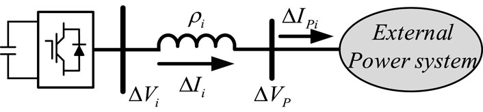
FIGURE 2. Configuration of the ith subsystem.
2.3 Aggregated representation
State transformation conducted in the previous subsection indicates that the cluster of M similar inverters in daisy-chain connection is approximately equivalent to M dynamically independent subsystems. In each independent subsystem, an inverter is connected to the external system via an equivalent reactance, which is an eigenvalue of matrix daisy-chain connection,
For the case of M similar inverters in parallel connection studied in Du et al. (2020b), M dynamically independent subsystems are obtained after state transformation. Each of the first (
Denote
where
From Eq. 6, it can be seen that
However, if the real part of
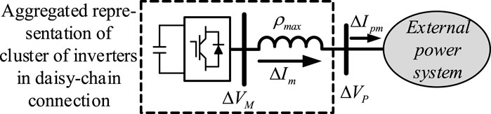
FIGURE 3. Aggregated representation for studying oscillatory stability of a cluster of similar inverters in a daisy-chain connection.
From Eqs 9 and 10 and Figure 3, the linearized model of the proposed aggregated representation can be written as follows:
where
The linearized model of the external system can be expressed as follows:
Thus, from Eqs 12 and 13, the linearized model of the entire power system in Figure 1 can be established as
where
The aggregated inverter in the case of inverters in daisy-chain connection is different to that derived from Du et al. (2020a) for the case of inverters in parallel connection as the lumped reactance for the two cases is different. The difference is due to the fact that two different forms of state transformation are applied for two different cases of inverters’ connection. A further examination of the difference is conducted as follows.
Assume that the cable that connects the cluster of inverters in the daisy-chain connection to the external system in Figure 1 is much longer than the cables inside the cluster, that is,
It is easy to prove that
Therefore, the analysis above indicates that the state transformation and the aggregated inverter derived from Du et al. (2020b) are just a special example of those in the current study about similar inverters in daisy-chain connection. Analysis and conclusions obtained from the special example in Du et al. (2020c) cannot be simply extended to the case of inverters in daisy-chain connection. Hence, the total impact of inverters in daisy-chain connection about how the inverters may collectively cause instability risk needs to be investigated as to be presented in the following subsection.
2.4 Impact of increasing number of inverters
First, the following theorem is introduced:
the Cauchy interlace theorem (Mercer and Mercer, 2000). Let
Second, consider that one more inverter is connected at the end of the daisy chain in Figure 1. According to the definition of the matrix of daisy-chain connection given in Eq. 6,
where
From Eqs 6 and 17, it can be seen that the matrix
Finally, according to the analysis conducted in the previous subsection, it is known that when
3 An example power system with a grid-connected photovoltaic power generation farm
Figure 4 shows the configuration of an example power system with a grid-connected PV power generation farm. In the PV farm, a cluster of inverters is in a daisy-chain connection. The AC power system consists of two synchronous generators (SG1 and SG2) connected to an infinite busbar. The 20th-order model recommended for subsynchronous oscillation studies in Padiyar (1996) is adopted for SG1 and SG2, with the parameters adjusted in line with their capacities. On the basis of previous work (Du et al., 2020a), the inverter adopts an 8th-order model, including DC capacitance voltage (1-order), control system (3-order), filter reactance (2-order), and PLL (2-order). The relevant parameters are shown in Supplementary Appendix S1B. Pc denotes the active power output from the cluster of inverters.
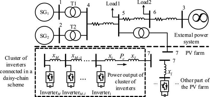
FIGURE 4. An example power system with a grid-connected PV power generation farm.
3.1 Case study 1: Aggregated representation
Initially, there are five inverters in the cluster of daisy-chain connections, that is, M = 5. At steady state, the power factor of each inverter is 0.98 with the active power output being 0.1 p.u. The parameters of the inverters and the converter control systems are the same. However, steady-state terminal voltages of the inverters are different (otherwise, there will be no load flow in the cluster). Hence, linearized models of five inverters in the cluster are slightly different instead of being identical. Analysis of the aggregated representation of a cluster of inverters in a daisy-chain connection is evaluated as follows.
First, the fifth inverter in the cluster, that is, inverter5 is selected to represent the other four inverters in the cluster, that is,
Second, the matrix of daisy-chain connections defined by Eq. 6 is derived, and its eigenvalues are calculated to be
Thus, the aggregated representation of the cluster of five inverters, shown in Figure 3, is obtained to be
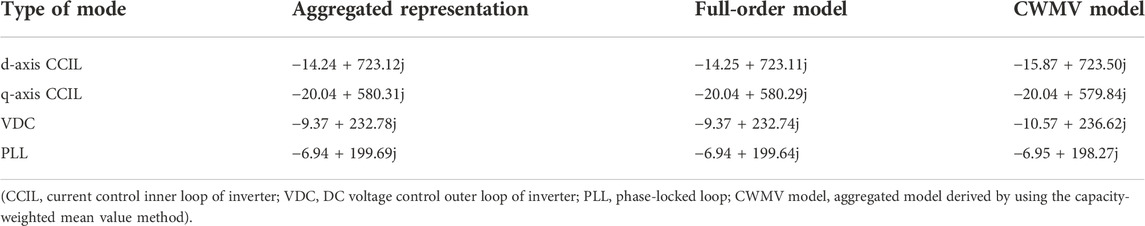
TABLE 1. Oscillation modes of the cluster of five inverters in daisy-chain connection (case study 1).
Third, for validation, a full-order model of the cluster of five inverters, as described in Eq. 3, is established, in which linearized models of the inverters are similar but slightly different. Oscillation modes are computed from the state matrix of the full-order model,
Participation factors of the oscillation modes are presented in Figure 5.
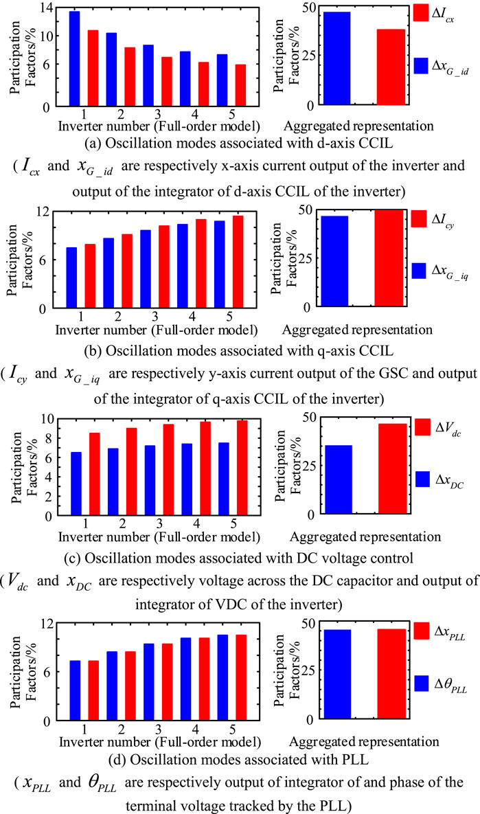
FIGURE 5. Computational results of participation factors (case study 1). (A) Oscillation modes associated with d-axis CCIL (
Finally, for comparison, the capacity-weighted mean value method (Zou et al., 2015; Zhou et al., 2018) is applied to derive an aggregated model of the cluster of five inverters in the daisy-chain connection in the example power system. Oscillation modes are computed by using the aggregated model derived by using the capacity-weighted mean value method. Computational results are listed in the 4th column of Table 1. From Table 1, it is obvious that the aggregated representation proposed in the previous section gives more accurate results in stability assessment than the aggregated model derived by using the capacity-weighted mean value method.
3.2 Case study 2: Increasing number of inverters
By using the aggregated representation obtained earlier, the sensitivity index defined by Eq. 11 is computed for the oscillation modes with variation in the value of
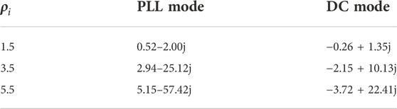
TABLE 2. Computational results of sensitivity index.
To evaluate this prediction, oscillation modes are computed by using the aggregated representation shown in Figure 3, the full-order model of Eq. 3, and the aggregated model derived by using the capacity-weighted mean value method. Results of modal computation with variation of the number of inverters in daisy-chain connection in the example power system give the trajectories of the PLL mode and DC mode presented in Figure 6. When more inverters are connected in the daisy chain in the PV farm, the same number of inverters in the other part of the PV farm is withdrawn from the operation. In order to exclude the impact of dynamics of the PVs in the other part of the PV farm, the PVs in the other part are modeled as constant power sources. Subsequently, the impact of a varied number of PVs is that dynamic interactions between the PVs and the steady-state power generation from the PV farm remain unchanged. The following observations can be made from Figure 6.
1) The PLL mode moves toward the right on the complex plane as the number of inverters in the daisy-chain connection increases. When 23 inverters are in daisy-chain connection,
2) The computational results obtained using aggregated representation are more accurate than those using the aggregated model from the capacity-weighted mean value method. The latter in fact fails to identify the oscillatory instability when the number of inverters in the daisy-chain connection is increased, indicating that the aggregated model derived by using the capacity-weighted mean value method is not applicable for the stability assessment in this case study.
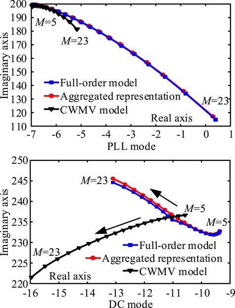
FIGURE 6. Trajectories of oscillation modes as M increased (case study 2, CWMV model, aggregated model derived by using the capacity-weighted mean value method).
Participation factors of the oscillation modes are presented in Figure 7.
FIGURE 7. Computational results of participation factors (case study 2, M = 23). (A) Oscillation modes associated with PLL. (B) Oscillation modes associated with DC voltage control.
Validation by non-linear simulation is given in Figure 8. At 0.5 s of simulation, the active power output over other parts of the PV farm in the example power system decreases by 5% for 0.1 s. From Figure 8, it can be seen that when 23 inverters are in a daisy-chain connection, growing oscillations occur, confirming the conclusion that inverters in a daisy-chain connection may collectively cause oscillatory instability and the effectiveness of the aggregated representation.
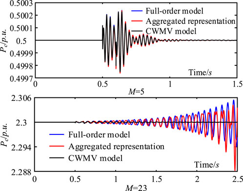
FIGURE 8. Non-linear simulation results (case study 2, CWMV model, aggregated model derived by using the capacity-weighted mean value method).
3.3 Case study 3: Dynamic models of the inverters are different
In the two study cases presented earlier, the parameters of inverters in daisy-chain connection are the same such that dynamic models of inverters are similar. In this study case, the parameters of inverters in daisy-chain connection are different. Consequently, the dynamic models of inverters in daisy-chain connection in the example power system are different. Evaluation of the analysis and conclusions made in the previous section is carried out as follows.
First, parameters of inverter5 are used as a base. Parameters of the control systems and the PLLs of other inverters in the daisy-chain connection in the example power system are varied from the base within the limit of ±10%. Subsequently, linearized models of the inverters in the daisy-chain connection are different. Results of modal computation are listed in Table 3. From Table 3, it can be noted that the results from modal computation using the aggregated representation are more accurate than those obtained using the aggregated model derived using the capacity-weighted mean value method, as compared with the results obtained using the full-order model.

TABLE 3. Oscillation modes of the cluster of five inverters in daisy-chain connection (case study 3).
Second, the impact of the increasing number of inverters in the daisy-chain connection is evaluated. Because the dynamic model of inverter5 is the same as that in case studies 1 and 2, computational results of the sensitivity index are the same as those given in Table 2. Hence, it is expected that when the number of inverters in the daisy-chain connection increases, damping of PLL mode would decrease and damping of the DC model would increase. Evaluation from modal computation and non-linear simulation are presented in Figures 9, 10, and 11, respectively. The results indicate that although the linearized models of the inverters in the daisy-chain connection are different in this case study, the analysis made under the condition that the linearized models of the inverters are similar is still valid. The small-signal oscillatory stability can be approximately assessed by using the aggregated representation. The increasing number of inverters in daisy-chain connection results in oscillatory instability. This confirms that multiple inverters in a daisy-chain connection may collectively induce instability risk. In addition, the aggregated representation proposed in the article provides more accurate results in stability assessment than the aggregated model derived by using the capacity-weighted mean value method.
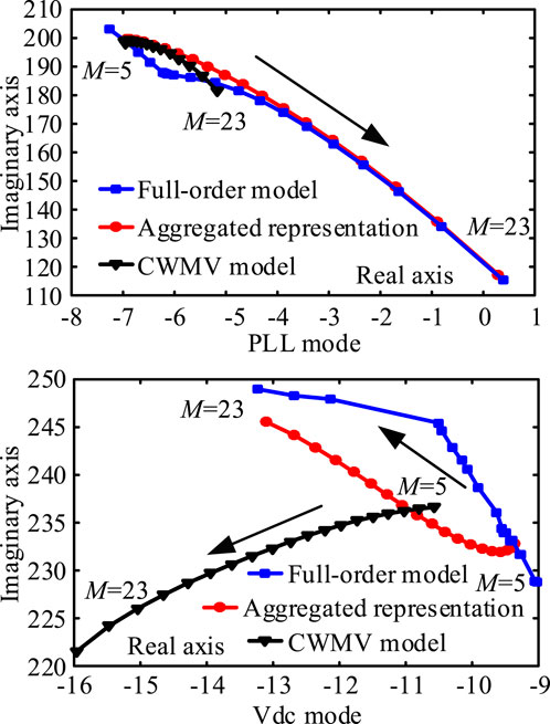
FIGURE 9. Trajectories of oscillation modes as M increases (case study 3).
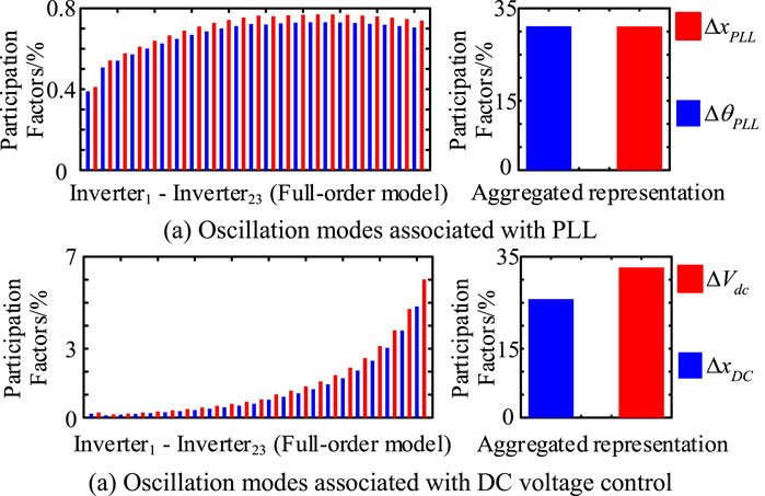
FIGURE 10. Computational results of participation factors (case study 1, M = 23). (A) Oscillation modes associated with PLL. (A) Oscillation modes associated with DC voltage control.

FIGURE 11. Non-linear simulation results (case study 3 similar parameters).
Third, when the dynamics of the PVs are similar, the model of any PV in the PV farm can be used as the aggregated model of the PV farm. However, when the dynamics of the PVS are considerably different, the error in assessing the stability by using the aggregated model of the PV farm may be large. This is demonstrated by the following study case.
Parameters of inverter5 remain unchanged. Deviation of values of parameters of other inverters in daisy-chain connection in the example power system from those of inverter5 increases above the limit of ±10%. Since inverter5 is used as the representative of inverters to establish the aggregated model of the example power system. Hence, the results of modal computation and simulation using the aggregated representation of the inverters in the daisy-chain connection are the same as those presented in the second column of Table 3 and Figure 11. When the deviation of parameters of inverters from those of inverter5 is ±20%, ±30%, ±40%, and ±50%, respectively, results of modal computation using the full-order model are presented in Tables 4 and 5, where the error of modal computation is
where
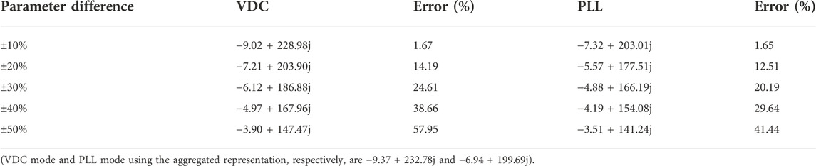
TABLE 4. Oscillation modes of the cluster of five inverters in daisy-chain connection with different parameter settings.
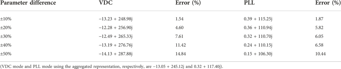
TABLE 5. Oscillation modes of the cluster of twenty-three inverters in daisy-chain connection with different parameter settings.
Results of the simulation are given in Figure 12.
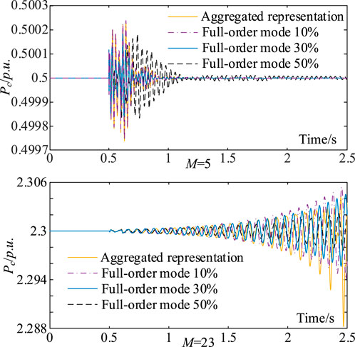
FIGURE 12. Non-linear simulation results (case study 3 different parameters).
From Tables 4 and 5 and Figure 12, it can be seen that when the deviation of parameters of inverters is within ±10%, the error to assess the stability between using the aggregated representation and using the full-order model is 1%∼2%, which is acceptable. However, when the deviation is over ±20% or more, the error is more than 5%, when the aggregated representation might not be acceptable.
3.4 Case study 4: External oscillation stability
In the study cases presented earlier, oscillatory stability of the cluster of inverters in a daisy-chain connection is examined. In the examination, the cluster of inverters is not connected to the external system. Hence, the examination is about the stability of the cluster of inverters as an open-loop subsystem. The examination is important because the instability of the cluster of the inverters shall cause the entire system to become unstable when the inverters are connected to the external system.
In this subsection, oscillatory stability with the cluster of inverters in the daisy-chain connection being connected to the external system is assessed. The assessment is about the stability of the entire system integrated with the cluster of the inverters. For the assessment, aggregated representation proposed in the previous section, the full-order model, and the aggregated model derived by using the capacity-weighted mean value method for the cluster of inverters in the daisy-chain connection are compared.
When the number of cluster of inverters in the cluster is 15, the cluster of inverters in the daisy-chain connection is stable before being connected to the external system, as being indicated by previous study cases. After the cluster of 15 inverters is connected to the external system, the aggregated representation of the cluster of inverters shown in Figure 3 is used to establish the state-space model of the entire example power system depicted by Eq. 14. Afterward, from the state matrix,
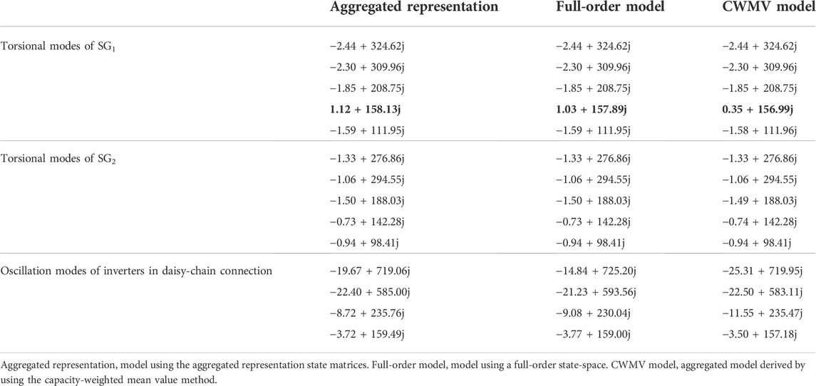
TABLE 6. External oscillation modes of the example power system (case study 4).
For confirmation, the full-order model of a cluster of 15 inverters in a daisy-chain connection is derived and integrated with the model of the external system. Subsequently, a full-order model of the entire example power system with the PV power generation farm is established. Results of modal computation are presented in the 3rd column of Table 6. It can be seen that the example power system is unstable, confirming the correctness of the assessment made by using the aggregated representation proposed.
Furthermore, the participation factors of the unstable torsional oscillation mode of SG1, 1.12 + 158.13j, are computed. Computational results are presented in Figure 13. It can be seen that the unstable torsional oscillation mode is associated with all 15 inverters in the daisy-chain connection. This confirms that the oscillatory instability is caused collectively by the cluster of inverters in the daisy-chain connection.

FIGURE 13. Computational results of participation factors (case study 4).
For confirmation, the full-order model of a cluster of 15 inverters in a daisy-chain connection is derived and integrated with the model of the external system. Subsequently, a full-order model of the entire example power system with the PV power generation farm is established. Results of modal computation are presented in the 3rd column of Table 4. It can be seen that the example power system is unstable, confirming the correctness of the assessment made by using the aggregated representation proposed.
Furthermore, the participation factors of the unstable torsional oscillation mode of SG1, 1.12 + 158.13j, are computed. Computational results are presented in Figure 12. It can be seen that the unstable torsional oscillation mode is associated with all 15 inverters in the daisy-chain connection. This confirms that the oscillatory instability is caused collectively by the cluster of inverters in the daisy-chain connection.
Computational results of the unstable torsional oscillation mode of SG1 with the change in the number of inverters in daisy-chain connection (M) are presented in Table 7. It can be seen that when M is reduced to 13, the example power system is stable. However, when M = 14, the example power system is unstable. The CWMV model fails to identify the danger of oscillation instability of the example power system in this case.
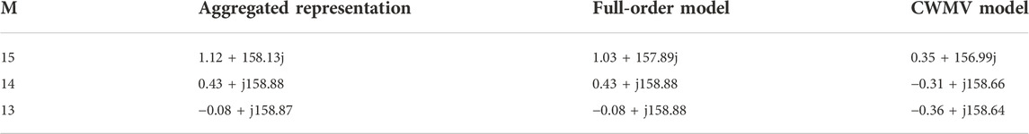
TABLE 7. Torsional oscillation mode of SG1 when M decreases (case study 4).
Results of validation by non-linear simulation using the full-order model are given in Figure 14.
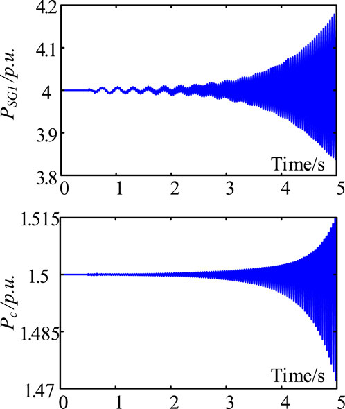
FIGURE 14. Non-linear simulation results (case study 4, full-order model used).
4 Conclusion
This study examines the total impact of a cluster of similar inverters in a daisy-chain connection, which is one of the most common basic configurations of PV power collecting network on the small-signal stability of a grid-connected PV power generation farm. The main conclusions and contributions made by the study are as follows:
1) An aggregated representation of the cluster of similar inverters in daisy-chain connection is derived for the stability study based on the dynamic equivalence. Hence, the derivation confirms the rationality of representing the cluster of similar inverters in daisy-chain connection by an aggregated inverter connected to the external grid via a lumped reactance.
2) Analysis is carried out to indicate that the cluster of similar inverters in the daisy-chain connection may collectively induce the growing oscillations in the PV farm. The analysis is carried out to indicate that the cluster of similar inverters in the daisy-chain connection may collectively induce the growing oscillations in the PV farm. Subsequently, an increasing number of inverters in the daisy-chain connection may increase the instability risk, although the total steady-state active power output from the grid-connected PV farm remains unchanged.
3) General topology of the power collecting network of a grid-connected PV farm is radial, with a combination of two basic configurations: daisy-chain connection and parallel connection. The article extends the pioneering study by Du et al. (2020c), which was about the total impact of inverters in a parallel connection.
Further study on the total impact of the increasing number of inverters on the small-signal stability of PV farms in the near future may be in two folds. First, it is the extension of stability analysis to the case of the general radial topology of the PV power collecting network. Second, it is the total impact when the dynamics of inverters are different.
There are two kinds of methods to tackle the instability risk. The first one is to tune the parameters of the PVs in the PV farm. The second is to assign damping controllers on the PVs or/and the PV farm. Both methods have been investigated in the literature. Hence, following-on work to be carried out in the near future will be the examination of applying those two methods to mitigate the instability risk brought about by the daisy-chain connection of PVs in the PV farm.
Data availability statement
The original contributions presented in the study are included in the article/Supplementary Material; further inquiries can be directed to the corresponding author.
Author contributions
YZ proposed this research direction and assigned the work. JC determined the research method and completed the main work. The rest of the work was carried out by JZ.
Funding
This work is supported by TBEA Science and Technology Investment Co., Ltd. “Research on modeling and broadband oscillation suppression of large-scale renewable energy bases (including pure photovoltaics) (TBEA-KJTZ-ZYYJ-2022-019).”
Conflict of interest
Authors YZ, JC, and JZ were employed by TBEA Science and Technology Investment Co., Ltd.
Publisher’s note
All claims expressed in this article are solely those of the authors and do not necessarily represent those of their affiliated organizations, or those of the publisher, the editors, and the reviewers. Any product that may be evaluated in this article, or claim that may be made by its manufacturer, is not guaranteed or endorsed by the publisher.
Abbreviations
References
Agorreta, J. L., Borrega, M., López, J., and Marroyo, L. (2011). Modeling and control of N-paralleled grid-connected inverters with LCL filter coupled due to grid impedance in PV plants. IEEE Trans. Power Electron. 26 (3), 770–785. doi:10.1109/TPEL.2010.2095429
Ali, M. N., Mahmoud, K., Lehtonen, M., and Darwish, M. M. (2021). An efficient fuzzy-logic based variable-step incremental conductance MPPT method for grid-connected PV systems. IEEE Access 9, 26420–26430. doi:10.1109/ACCESS.2021.3058052
Callegaro, L., Rojas, C. A., Ciobotaru, M., and Fletcher, J. E. (2022). A controller improving photovoltaic voltage regulation in the single-stage single-phase inverter. IEEE Trans. Power Electron. 37 (1), 354–363. doi:10.1109/TPEL.2021.3100530
Du, W., Dong, W. K., Wang, H., and Cao, J. (2019). Dynamic aggregation of same wind turbine generators in parallel connection for studying oscillation stability of a wind farm. IEEE Trans. Power Syst. 34 (6), 4694–4705. doi:10.1109/TPWRS.2019.2920413
Du, W., Zheng, K. Y., and Wang, H. F. (2020a). Instability of a DC microgrid with constant power loads caused by modal proximity. IET Generation, Transm. Distribution 14 (5), 774–785. doi:10.1049/iet-gtd.2019.0696gtd.2018.6940
Du, W., Fu, Q., and Wang, H. F. (2020b). Stability of small-gain closed-loop system and its applications in VSC-based DC/AC power systems. Electr. Power Components Syst. 47 (18), 1610–1622. doi:10.1080/15325008.2019.1689455
Du, W., Ma, Z., Wang, Y., and Wang, H. F. (2020c). Harmonic oscillations in a grid-connected PV generation farm caused by increased number of parallel-connected PV generating units and damping control. CSEE JPES. 1–9. doi:10.17775/CSEEJPES.2020.02790
Du, W., Dong, W. K., Wang, Y., and Wang, H. F. (2021a). Small-disturbance stability of a wind farm with virtual synchronous generators under the condition of weak grid connection. IEEE Trans. Power Syst. 36 (6), 5500–5511. doi:10.1109/TPWRS.2021.3080700
Du, W., Wang, Y., Wang, H. F., Yu, J., and Xiao, X. Y. (2021b). Collective impact of multiple doubly fed induction generators with similar dynamics on the oscillation stability of a grid-connected wind farm. IEEE Trans. Power Deliv. 36 (5), 2942–2954. doi:10.1109/TPWRD.2020.3030645
Du, W., Wang, Y., Wang, H. F., and Xiao, X. Y. (2021c). Reduced-order method for detecting the risk and tracing the sources of small-signal oscillatory instability in a power system with a large number of wind farms. IEEE Trans. Power Syst. 36 (2), 1563–1582. doi:10.1109/TPWRS.2020.3020041
Fu, Q., Du, W., and Wang, H. F. (2020). Planning of the DC system considering restrictions on the small-signal stability of EV charging stations and comparison between series and parallel connections. IEEE Trans. Veh. Technol. 69 (10), 10724–10735. doi:10.1109/TVT.2020.3006480
Guo, X., Yang, Y., Wang, B., and Blaabjerg, F. (2018). Leakage current reduction of three-phase Z-source three-level four-leg inverter for transformerless PV system. IEEE Trans. Power Electron. 34 (7), 6299–6308. doi:10.1109/TPEL.2018.2873223
Harnefors, L., Bongiorno, M., and Lundberg, S. (2007). Input-admittance calculation and shaping for controlled voltage-source converters. IEEE Trans. Ind. Electron. 54 (6), 3323–3334. doi:10.1109/TIE.2007.904022
Harnefors, L. (2007). Analysis of subsynchronous torsional interaction with power electronic converters. IEEE Trans. Power Syst. 22 (1), 305–313. doi:10.1109/TPWRS.2006.889038
Huang, Y., Yuan, X., Hu, J., and Zhou, P. (2015). Modeling of VSC connected to weak grid for stability analysis of DC-link voltage control. IEEE J. Emerg. Sel. Top. Power Electron. 3 (4), 1193–1204. doi:10.1109/JESTPE.2015.2423494
Kroutikova, N., Hernandez-Aramburo, C. A., and Green, T. C. (2007). State-space model of grid-connected inverters under current control mode. IET Electr. Power Appl. 1 (3), 329–338. doi:10.1049/iet-epa:20060276
Liu, S., Liu, P. X., and Wang, X. (2016). Stability analysis of grid-interfacing inverter control in distribution systems with multiple photovoltaic-based distributed generators. IEEE Trans. Ind. Electron. 63 (12), 7339–7348. doi:10.1109/TIE.2016.2592864
Majumder, R., and Bag, G. (2014). Parallel operation of converter interfaced multiple microgrids. Int. J. Electr. Power & Energy Syst. 55, 486–496. doi:10.1016/j.ijepes.2013.09.008
Malik, S. M., Sun, Y., Ai, X., Chen, Z., and Wang, K. (2019). Small-signal analysis of a hybrid microgrid with high PV penetration. IEEE Access 7, 119631–119643. doi:10.1109/ACCESS.2019.2937123
Mercer, A. M., and Mercer, P. R. (2000). Cauchy's interlace theorem and lower bounds for the spectral radius. Int. J. Math. Math. Sci. 23 (8), 563–566. doi:10.1155/s016117120000257x
Moradi-Shahrbabak, Z., and Tabesh, A. (2018). Effects of front-end converter and DC-link of a utility-scale PV energy system on dynamic stability of a power system. IEEE Trans. Ind. Electron. 65 (1), 403–411. doi:10.1109/TIE.2017.2721902
Pan, Y., Sangwongwanich, A., Yang, Y., and Blaabjerg, F. (2020). A phase-shifting MPPT to mitigate interharmonics from cascaded H-bridge PV inverters. IEEE Trans. Ind. Appl. 57 (3), 3052–3063. doi:10.1109/TIA.2020.3000969
Peng, X., and Yang, H. (2020). Impedance-based stability criterion for the stability evaluation of grid-connected inverter systems with distributed parameter lines. CSEE JPES. 1–13. doi:10.17775/CSEEJPES.2019.02250
Sangwongwanich, A., and Blaabjerg, F. (2019). Mitigation of interharmonics in PV systems with maximum power point tracking modification. IEEE Trans. Power Electron. 34 (9), 8279–8282. doi:10.1109/TPEL.2019.2902880
Shah, C., Vasquez-Plaza, J. D., Campo-Ossa, D. D., Patarroyo-Montenegro, J. F., Guruwacharya, N., Bhujel, N., et al. (2021). Review of dynamic and transient modeling of power electronic converters for converter dominated power systems. IEEE Access 9, 82094–82117. doi:10.1109/ACCESS.2021.3086420
Shahnia, F. (2016). Stability and eigenanalysis of a sustainable remote area microgrid with a transforming structure. Sustain. Energy Grids Netw. 8, 37–50. doi:10.1016/j.segan.2016.09.005
Tan, Y. T., Kirschen, D. S., and Jenkins, N. (2004). A model of PV generation suitable for stability analysis. IEEE Trans. Energy Convers. 19, 748–755. doi:10.1109/TEC.2004.827707
Wang, X., Freitas, W., Dinavahi, V., and Xu, W. (2009). Investigation of positive feedback anti-islanding control for multiple inverter-based distributed generators. IEEE Trans. Power Syst. 24 (2), 785–795. doi:10.1109/TPWRS.2008.2007002
Wang, S. (2020). Current status of PV in China and its future forecast. CSEE JPES 6 (1), 72–82. doi:10.17775/CSEEJPES.2019.03170
Wen, B., Boroyevich, D., Burgos, R., Mattavelli, P., and Shen, Z. (2015). Small-signal stability analysis of three-phase AC systems in the presence of constant power loads based on measured d-q frame impedances. IEEE Trans. Power Electron. 30 (10), 5952–5963. doi:10.1109/TPEL.2014.2378731
Xia, Y., Yu, M., Wang, X., and Wei, W. (2018). Describing function method based power oscillation analysis of LCL-filtered single-stage PV generators connected to weak grid. IEEE Trans. Power Electron. 34 (9), 8724–8738. doi:10.1109/TPEL.2018.2887295
Zhao, Z., Yang, P., Wang, Y., Xu, Z., and Guerrero, J. M. (2017). Dynamic characteristics analysis and stabilization of PV-based multiple microgrid clusters. IEEE Trans. Smart Grid 10 (1), 805–818. doi:10.1109/TSG.2017.2752640
Zhou, Y., Zhao, L., and Lee, W. J. (2018). Robustness analysis of dynamic equivalent model of DFIG wind farm for stability study. IEEE Trans. Ind. Appl. 54 (6), 5682–5690. doi:10.1109/TIA.2018.2858738
Zhou, B., Shi, P., Xu, Y., and Zeng, Z. (2022). Impact of electrical connection distance on the open loop modal resonance of grid connected photovoltaic farms. Front. Energy Res. 10, 872143. doi:10.3389/fenrg.2022.872143
Zhu, X., Wang, H., Zhang, W., Wang, H., Deng, X., and Yue, X. (2020). A novel single-phase five-level transformer-less photovoltaic (PV) inverter. Trans. Electr. Mach. Syst. 4 (4), 329–338. doi:10.30941/CESTEMS.2020.00040
Keywords: small-signal stability, photovoltaic power generation farm, dynamic equivalence, linearized state-space model, modal analysis
Citation: Zhou Y, Cao J and Zhao J (2023) Small-signal oscillatory stability of a grid-connected PV power generation farm affected by the increasing number of inverters in daisy-chain connection. Front. Energy Res. 10:1022060. doi: 10.3389/fenrg.2022.1022060
Received: 18 August 2022; Accepted: 12 September 2022;
Published: 05 January 2023.
Edited by:
Siqi Bu, Hong Kong Polytechnic University, Hong Kong SAR, ChinaReviewed by:
Qiang Fu, Sichuan University, ChinaJun Cao, Luxembourg Institute of Science and Technology (LIST), Luxembourg
Bowen Zhou, Northeastern University, China
Copyright © 2023 Zhou, Cao and Zhao. This is an open-access article distributed under the terms of the Creative Commons Attribution License (CC BY). The use, distribution or reproduction in other forums is permitted, provided the original author(s) and the copyright owner(s) are credited and that the original publication in this journal is cited, in accordance with accepted academic practice. No use, distribution or reproduction is permitted which does not comply with these terms.
*Correspondence: Yi Zhou, emhvdXlpQHRiZWEuY29t