 R. Palanisamy1
 V. Shanmugasundaram2
 M. Lakshmi3
 B. Karthikeyan4
 Kareem M. Aboras5
 Mohit Bajaj6,7Mohammad Alsharef8Ehab E. Elattar8
 Salah Kamel9*
- 1Department of Electrical and Electronics Engineering, SRM Institute of Science and Technology, Chennai, India
- 2Department of Electrical and Electronics Engineering, Sona College of Technology, Salem, India
- 3Department of Electrical and Electronics Engineering, Dhanalakshmi Srinivasan University, Trichy, TN, India
- 4Department of Electrical and Electronics Engineering, K. Ramakrishnan College of Technology, Trichy, India
- 5Department of Electrical Power and Machines, Faculty of Engineering, Alexandria University, Alexandria, Egypt
- 6Department of Electrical Engineering, Graphic Era (Deemed to be University), Dehradun, India
- 7Department of Electrical and Electronics Engineering, National Institute of Technology, Delhi, India
- 8Department of Electrical Engineering, College of Engineering, Taif University, Taif, Saudi Arabia
- 9Electrical Engineering Department, Faculty of Engineering, Aswan University, Aswan, Egypt
In this paper, Three Dimensional Space Vector Pulse Width Modulation (3D-SVPWM) is developed to obtain the performance analysis of a 3-phase matrix converter (MC). MC is used to convert 3-phase fixed AC voltage to 3-phase variable AC voltage, which provides superior performance compared to conventional AC to AC converters. The 9-bidirectional power switches in a 3-phase matrix converter are controlled by appropriate gating pulses utilizing 3D-SVPWM. In conventional AC to AC power converters, the common mode voltage is induced across the load terminal, which causes bearing failure and EMI issues and so leads to increased total harmonic distortion (THD). Implementing the 3D-SVPWM approach with the nearest switching state vector (NSV) selection mechanism alleviates these problems. In proposed system, CMV is reduced to 37 V, which is equivalent to a Vdc/8 time of the supplied AC input voltage and THD of 3-phase to 3-phase MC is reduced to 1.12% for output voltage and 2.18% for output current. The output findings of the simulation and real-time simulator are verified using the Matlab Simulink model and the HIL real-time (OPAL-RT) simulator.
1 Introduction
In recent days, Power electronic converters have played a vital role in the field of engineering and technology, medical, energy transformation, industrial applications, electronics in power system applications, and railway unit (Empringham et al., 2013). Design and implementation of power converters are more significant to progress the quality of power and meet the power demand (Kolar et al., 2011)- (Oubelaid et al., 2022a). With the help of power converters, one form of energy is convertered to another form of energy; for example, inverter, rectifier, chopper, ac voltage controller, cycloconverter, and matrix converter. Among that, inverter and rectifier circuits are mostly used for various AC and DC load applications to meet desired output. Conventionally, AC to AC conversion is achieved through two stages process AC-DC-AC conversion; employing a rectifier unit and inverter system to obtain fixed ac voltage to variable ac voltage (Rodriguez et al., 2012). Also, AC voltage controllers and cycloconverters are used for ac to ac conversion. However, these converters are not ready to give adequate control on frequency and voltage with decreased ripples (Huber and Borojevic, 1995).
Nowadays, MCs are developed to obtain the desired range of frequency and voltage with reduced harmonic levels (Rivera et al., 2013)- (Karthikeyan et al., 2021). It offers better performance compared to conventional ac to ac power converters in terms of no lower order harmonics and fewer higher order harmonics (Agarwal and Agarwal, 2012). This converter affords advanced features like maximum utilization of ac input voltage, reduced harmonics, controlled power factor, bidirectional power flow control, minimized power loss, avoiding of dc link filter circuits, and zero switching control mode of operation (Oubelaid et al., 2022b)- (Dabour et al., 2014). It requires more power semiconductor switches for MC design compared to traditional rectifier-inverter pair circuits. Firstly 3-phase to 3-phase MC is introduced and modulated by Alesina and Venturini; then, later on, various modified circuits are designed and controlled by various PWM schemes (Meng et al., 2022).
Generally, different PWM strategies were developed to control the power devices located in altered power converter circuits (Tekwani et al., 2009; Palanisamy et al., 2021). Among that, Sinusoidal PWM, phase disposition, phase opposes disposition, single and multicarrier PWM, nearest state vector control, and Space vector modulation (SVM) was developed for MC circuits (Palanisamy et al., 2022). In these methods (McGrath et al., 2013; Muktiadji et al., 2022), SVM provides superior recital compared to other classical PWM strategies in terms of reduced harmonics, more utilization of applied ac voltage, minimized switching losses, better selection of switching state vectors, reduction in common mode voltage, avoids filter circuit utilization, and low EMI issues (Hao et al., 2022)- (Palanisamy and Krishnasamy, 2017).
Common mode voltage and total harmonic distortion are the two major issues in power electronic converters; it leads to affect the performance of the system (Dabour et al., 2015). Specifically, CMV directs to increase the common mode current and causes for bearing failure of the electric motor (Li and Yun, 2017). THD directs to increase in output current magnitudes and unbalanced output voltage in the grid system; it may cause the load demand and damage the various electrical equipment of the consumers. To eliminate the above issues, various control strategies were developed under different PWM schemes (Songtao et al., 2017)- (Jeevan et al., 2017). Also source impedance is placed between the applied source and converter circuit to minimize the harmonic level in source current and voltage unbalancing (Ahoora and Mehdi, 2018). Input filter and isolation transformer are located to provide reduced harmonics in the input current and smoothen input voltage to the proposed converter system (Oubelaid et al., 2022c; Oubelaid et al., 2022d).
In this projected paper, 3D-SVPWM is developed to attain the recital investigation of 3-phase MC. Matrix converter is used to renovate 3-phase fixed AC voltage to 3-phase variable AC voltage, which offers advanced recital compared to conformist AC to AC converters. Using 3D-SVPWM with the NSV selection approach, bearing failure and EMI concerns are reduced. In comparison to traditional PWM approaches, the suggested system has outstanding behaviour. The simulation and real-time simulator output results are verified using the Matlab Simulink model and HIL real-time (OPAL-RT) simulator.
2 3-phase to 3-phase matrix converter
Figure 1 shows the control strategies for the proposed 3D-SVPWM for MC. This proposed system includes a 3-phase AC input source, source impedance, input filter, isolation transformer, 3-phase to 3-phase MC, and grid system. Where MC provides 3-phase fixed AC voltage to 3-phase variable AC voltage and frequency. And input filter and isolation transformer are connected between the input voltage and MC to diminish the harmonic level in the input source current and electrical isolation between the devices. Phase locked loop is located between the matrix converter and grid system to provide proper synchronization; it checks the voltage magnitude, phase angle, frequency, and harmonic level between these two devices. HIL real-time simulator (OPAL-RT) is used for the implementation of 3D-SVPWM for MC, where the switching pulses are produced by converting the Matlab model to code through the various steps used in the HIL simulator.
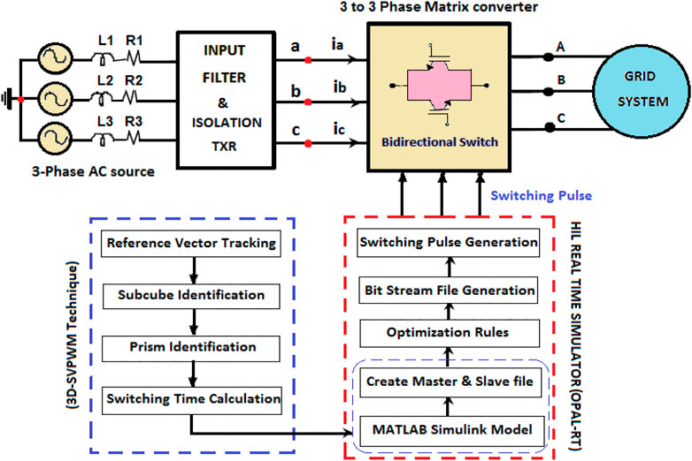
FIGURE 1. Control strategies for proposed 3D-SVPWM for MC.
The 3-phase to 3-phase MC comprises nine bidirectional switches for converting 3-phase fixed AC voltage to 3-phase variable AC voltage, which is shown in Figure 2. Based on the gating pulse generation, the bidirectional switches are controlled to obtain the variable AC output. The output power attained from the system is not equal to the applied input power; the energy is engrossed or dispersed due to the internal passive components like the inductor and capacitor.
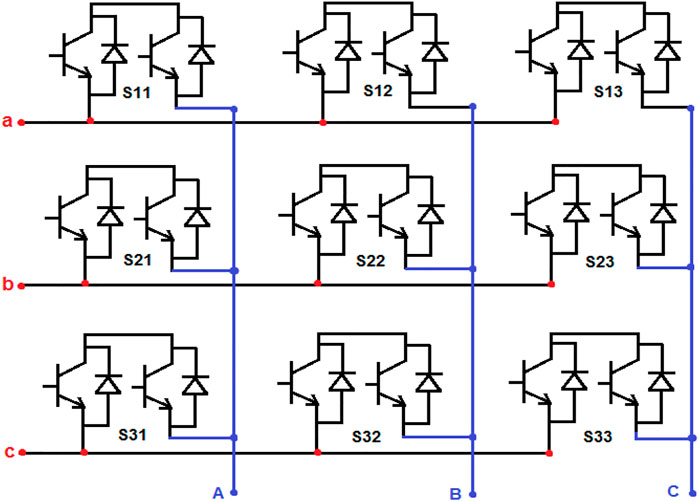
FIGURE 2. 3-Phase to 3-phase MC.
This system is made up of nine bidirectional switches organized into three groups, each with three bidirectional switches. The MC’s input and output voltages are coupled to each bidirectional switch; it is shown in Figure 3A. The input voltage is represented by a,b, and c, while the output voltage terminals of the MC are represented by A, B, and C. Three-phase to three-phase MC contains a total of 27 different switching modes, among that 19 are active switching states, three are null states, three are normal states, and three are inverse switching states. Bidirectional switches are turned ON based on the rotational concept, which avoids switching two devices in the same phase. In zero vector modes, a single input voltage phase connects all of the output phases; It damages the system when a 3-phase load or any motor load is connected to the system’s single input phase. Other vector modes like active and inverse vectors are used for operating the electrical drive under forward and reverse modes of operation. In active mode, the MC can generate the non-fluctuated ac output voltage, which is shown in Figure 3B.
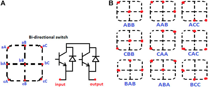
FIGURE 3. Matrix converter (A) Bidirectional switch (B) Active switching modes.
3 Implementation of three dimensional space vector pulse width modulation for 3-phase matrix converter
There is no redundancy in switching states in the 3D-SVPWM; each vertex point has its own switching state. As a result, calculating the switching time is easier than with traditional SVPWM. There are no park conversions or angle determinations required in the mathematical design calculations. As a result, when compared to two-dimensional space vector modulations (2D-SVPWM), the system can produce a higher level of CMV mitigation, and the capacitor balancing issue is also minimized. Figure 4 shows a comparison of 2D-SVPWM and 3D-SVPWM for switching pulse production for 2D-SVPWM and 3D-SVPWM. In that 2D-SVPWM includes sector tracking, triangle track, and switching time calculations are analyzed using trigonometric and lookup tables. But in 3D-SVPWM, the switching times are calculated without using any external parameters and calculations.
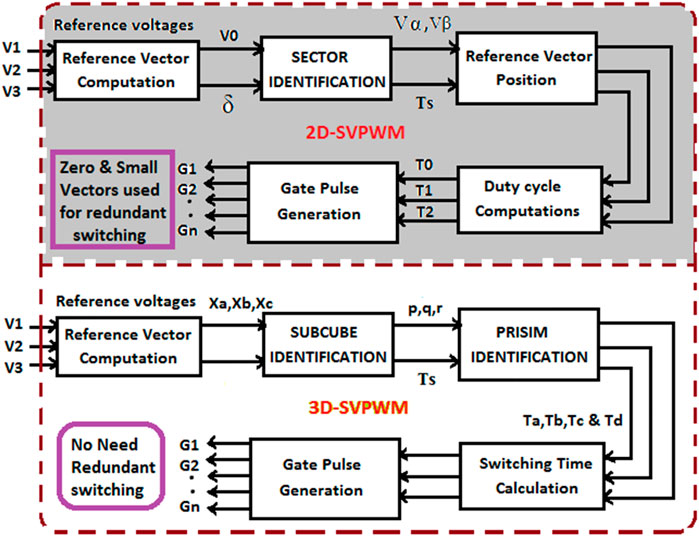
FIGURE 4. Comparison of switching pulse generation for 2D-SVPWM and 3D-SVPWM.
A. Steps for analysis of 3D-SVPWM.
✓ 1Capturing a subcube reference vector point in the 3D-SVPWM cube space plane.
✓ The prism reference vector in the subcube is being tracked.
✓ The switching times are calculated.
The cubic structure in 3D–SVPWM is made up of eight subcubes and is enclosed with 27 switching states. There are six prisms in each subcube, and each prism has four switching vectors in four vertex points. The reference point is captured by subcube and prism in the 3D-cubic space plane for n-phase and 3-phase switching pulses, as illustrated in Figures 5A,B.
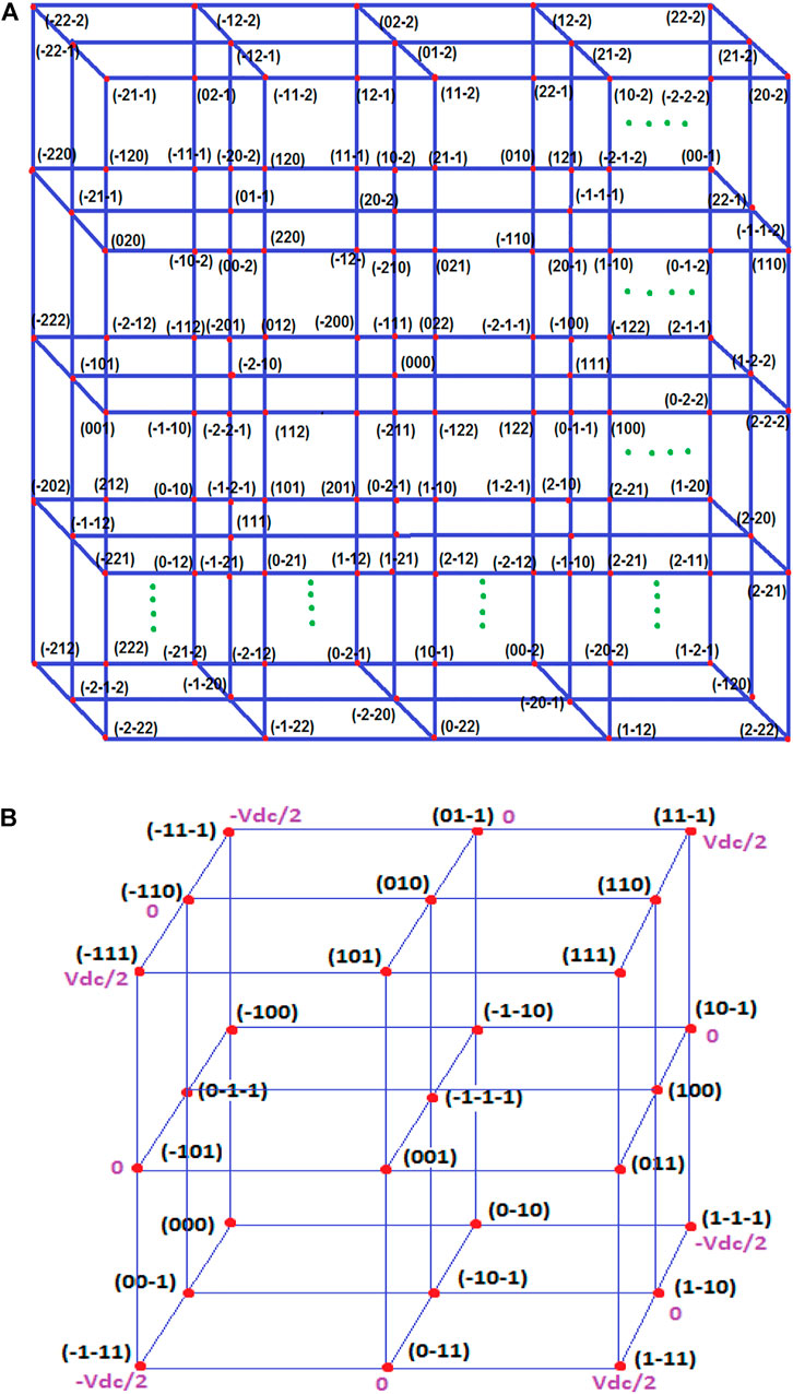
FIGURE 5. Representation of 3D-SVPWM (A) n-phase (B) 3-phase.
The proposed 3D-SVPWM algorithm estimates the four switching state vectors obtained by the reference vector computation quickly and easily. As a result, the reference vector will point to the prisms in the 3D-cubic plane. The switching state vectors of the switching sequence are represented by the prism’s vertices. The technique allows for the corresponding switching times to be achieved without the use of any pre-calculated look-up tables or any fixed mathematical formulas. The number of levels in the inverter system and the voltage level value of the dc-link capacitors determine the normalizing voltage vectors set in 3D-cubic. The reference voltage vector is divided into two parts as follows:
Where,
It is written in a-b-c coordinates as.
The reference voltage vector’s offset component is defined as
The two-level components
Extending a novel 3D-SVPWM for multilayer converter for a recompensing homo polar component in active power filters with neutral with single-phase disfigure loads that cause significant neutral currents is critical. The switching voltage vectors of a 3-level NPC inverter are embodied in a three-dimensional cubic space plane partitioned into eight subcubes to capture the position of reference vectors. To calculate four switching space vectors, this subcube space plane was split into six prisms once again. The reference vector location in various prisms is shown in Figure 6. The integer part of each component (a, b, c) is anticipated for a given normalized reference vector in 3-phase coordinates (Xa, Xb, Xc), where,
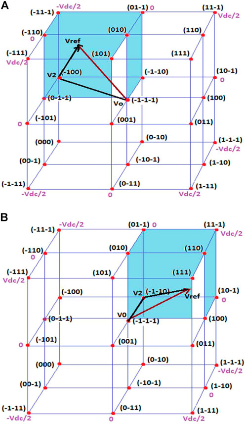
FIGURE 6. Reference vector location in subcubes (A) Subcube 1 (B) Subcube 2.
Depending on the number of levels in the inverter, the 3D-cubic space plane is moulded by a particular number of subcubes. A 3-phase n-level inverter typically has (n-1)3 subcubes. There are eight subcubes available in this 3-phase 3-level NPC inverter circuit. The origin coordinates (a, b, c) are equivalent to the subcube’s reference system where the reference vector is pointed. To progress the precision of reference recognition, the subcubes are divided into a number of prisms once again. Each subcube is alienated into six prisms, which is shown in Figure 7.
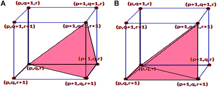
FIGURE 7. Reference vector location in prisms (A) Prism 1 (B) Prism 2.
The second state vector Xb is formed by the rounded integer values of these normalized two-level 3D-cubic vectors, and the third state vector Xc is formed by the important rounded integer values. Figure 8A shows the switching pulse production pattern of the NSV with3D-SVPWM. Figure 8B shows the switching pattern for NSV-based 3D-SVPWM. The switching time calculations of prism one can be stated based on NSV as
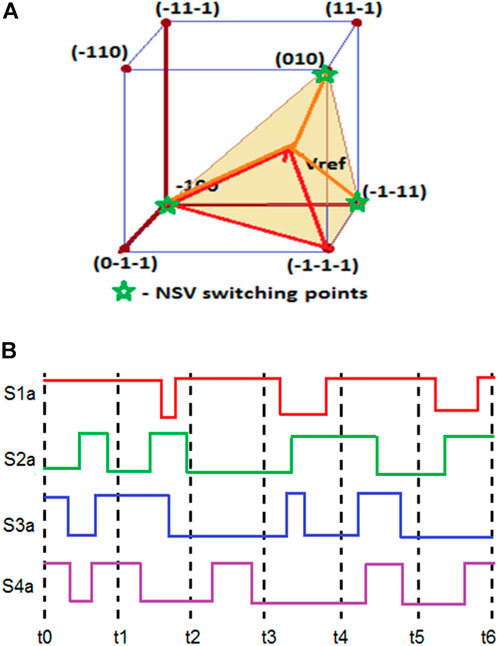
FIGURE 8. NSV-based 3D-SVPWM (A) Switching States located in Prism 1 (B) Pattern of Switching Pulse.
In general, the switching time computations of various prisms can be expressed as
The mathematical consideration of the switching time computation for various prisms positioned in various subcubes is abridged into a simple general structure with coordinates of (x, y, z) used, which is tabulated in Table 1. A flowchart for the process involved in the implementation of NSV with the 3D-SVPWM method is exposed in Figure 9.
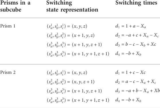
TABLE 1. Switching time computation for various prisms in a subcube.
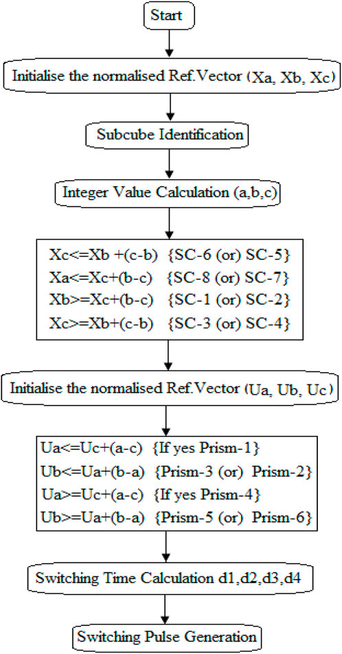
FIGURE 9. Flowchart for the process involved in NSV—3D-SVPWM.
4 Simulation results
The performance of 3-phase to 3-phase MC using 3D-SVPWM with NSV scheme is designed and analyzed using MATLAB. The performance of 33-phase MC with 3D-SVPWM is analyzed with 300 V AC input voltage. The 3-phase MC has a total of nine bidirectional IBGT power switches, in that each phase has 3-bidirectional switches. This proposed scheme with a coupled inductor of 4 mH for synchronizing MC output with three phases grid-connected system. Figure 10 shows the output voltage of 3-phase MC in that Figure 10A shows the output voltage of MC with hysteresis current control, which is not properly balanced; and Figure 10B shows the output voltage of MC using 2D-SVPWM with a voltage of 289 V; and Figure 10C shows the MC output voltage using 3D-SVPWM with balanced voltage of 300 V. Similarly, Figure 11 shows the output current of 3-phase MC; in that Figure 11A and Figure 11B shows the MC output current using hysteresis control and 2D-SVPWM with the current of 18.1 A and 18.6 A, respectively. And Figure 11C shows the MC output current using 3D-SVPWM with the current of 19.8 A; among these methods, 3D-SVPWM affords enhanced performance in terms of balanced output voltage and current generation for 3-phase MC.
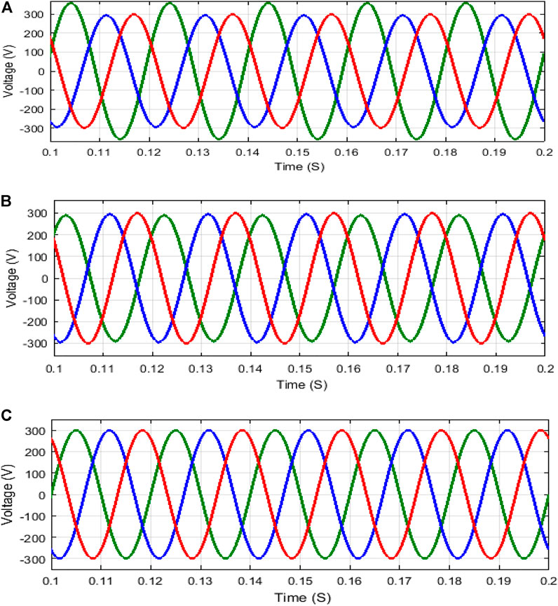
FIGURE 10. Output voltage of 3-phase MC (A) Hysteresis Control (B) 2D-SVPWM (C) 3D-SVPWM.
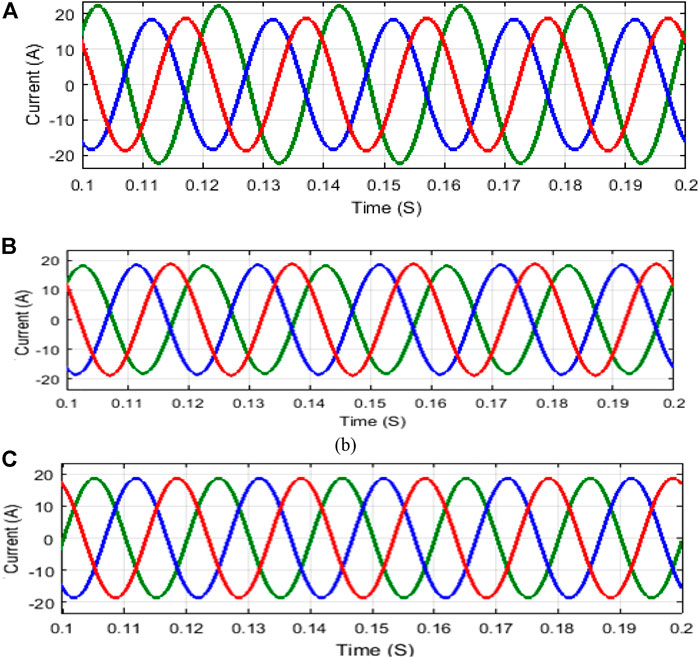
FIGURE 11. Output current of 3-phase MC (A) Hysteresis Control (B) 2D-SVPWM (C) 3D-SVPWM.
Figure 12 shows the THD examination for 3-phase MC; in that Figure 12A shows the THD analysis for output voltage with 1.12% and Figure 12B shows the THD examination for output current with 2.18%. The CMV calculation of 3-phase MC is exposed in Figure 13. Here Figure 13A explains the CMV diminution using hysteresis control with 100V, which is Vdc/3 times of supplied AC input voltage and Figure 13B illustrates the CMV diminution using 2D-SVPWM with 61.2 V, which is approximately Vdc/5 times of supplied AC input voltage; and Figure 13C illustrates the CMV diminution using 3D-SVPWM with 37 V, which is Vdc/8 times of supplied AC input voltage. In comparison to traditional PWM approaches, the suggested 3D-SVPWM clearly delivers greater CMV minimization.
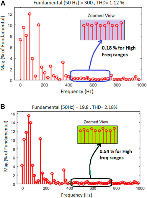
FIGURE 12. THD examination of 3-phase MC (A) Output voltage (B) Output current.
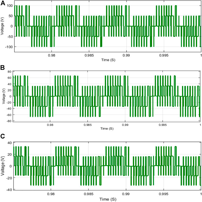
FIGURE 13. CMV calculation of 3-phase MC (A) Hysteresis Control (B) 2D-SVPWM (C) 3D-SVPWM.
5 HIL real-time simulator results
HIL real-time simulator setup of 3-phase MC design and expertise were used to verify the simulation findings of the proposed scheme. MC converts a fixed 3-phase input voltage to a variable voltage and frequency levels. The input filter is used in front of the MC to remove current harmonics. The output of the MC is coupled to a three-phase grid-connected system that is controlled using the OPAL-RT simulator and the 3D-SVPWM approach based on NSV. HIL’s real-time simulator control strategy is shown in Figure 14; it includes the Matlab Simulink file with main and output display blocks, real-time target unit, and PC with the control unit.
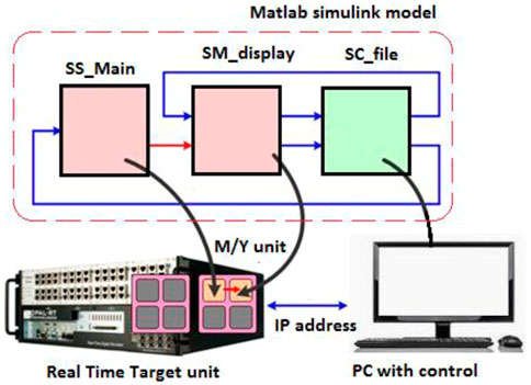
FIGURE 14. HIL real-time simulator control strategy.
The switching pulse production for the proposed 3-phase to 3-phase MC is obtained using the 3D-SVPWM control method, which is exposed in Figure 15. Figure 16 shows the output voltage and current of 3-phase to 3-phase MC. In that Figure 16A shows the output voltage 3-phase MC with a voltage of 299.5 V has THD of 1.48% and Figure 16A shows the output current of 3-phase MC with the current of 19.4 A has THD of 2.78%.
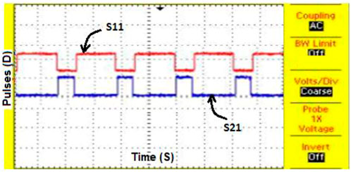
FIGURE 15. 3D-SVPWM with NSV for switching pulse generation.
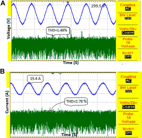
FIGURE 16. 3-phase MC (A) THD-Output voltage (B) THD-Output current.
The nearest switching stator vector selection approach is used to reduce CMV in 3-phase MC. Figure 17 shows the CMV diminution using NSV with the 3D-SVPWM method; it is abridged to Vdc/8 times of supplied ac input voltage. In comparison to traditional PWM approaches, the suggested technology clearly provides excellent CMV reduction. Table 2 assesses results for different PWM systems for CMV, output voltage, and THD reduction.
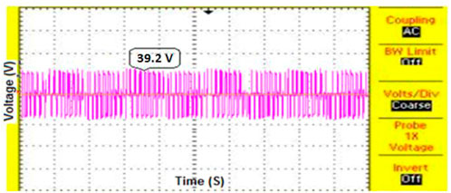
FIGURE 17. CMV reduction for MC using 3D-SVPWM.

TABLE 2. Result assessment for different PWM systems for CMV, output voltage, and THD reduction.
6 Conclusion
In this paper, a 3-phase to 3-phase MC is designed and developed for a grid-connected system using the 3D-SVPWM technique. With the use of an MC, fixed AC voltage is transformed to variable AC voltage and frequency; it has more advantages compared to conventional converters like reduced total harmonic distortion, reduced common mode voltage, low switching losses, and controlled output current. The CMV and bearing failure issues are reduced by implementing the 3D-SVPWM method with the NSV process selection scheme. This proposed system was validated with the help of the HIL real-time (OPAL-RT) simulator by synchronizing with the Matlab Simulink platform.
The following are the highlights of the paper:
✓ CMV is lowered to 37 V, which is equivalent to a Vdc/8 time of the supplied AC input voltage.
✓ THD of 3-phase to 3-phase MC is reduced to 1.12 percent for output voltage and 2.18 percent for output current.
✓ For 3-phase MC, NSV with 3D-SVPWM is designed and tested using the HIL real-time simulator.
Data availability statement
The raw data supporting the conclusions of this article will be made available by the authors, without undue reservation.
Author contributions
All authors listed have made a substantial, direct, and intellectual contribution to the work and approved it for publication.
Funding
This work was supported by Taif University Researchers Supporting Project number (TURSP-2020/86): Taif University, Taif, Saudi Arabia.
Conflict of interest
The authors declare that the research was conducted in the absence of any commercial or financial relationships that could be construed as a potential conflict of interest.
Publisher’s note
All claims expressed in this article are solely those of the authors and do not necessarily represent those of their affiliated organizations, or those of the publisher, the editors and the reviewers. Any product that may be evaluated in this article, or claim that may be made by its manufacturer, is not guaranteed or endorsed by the publisher.
References
Agarwal, A., and Agarwal, V. (2012). Field programmable gate array-based delta-modulated cycloinverter. IET Power Electron. 5 (9), 1793–1803. doi:10.1049/iet-pel.2011.0476
Ahoora, B., and Mehdi, N. (2018). “Capacitor voltage balancing of a nested T-type four-level inverter using space vector modulation,” in IEEE Applied Power Electronics Conference and Exposition (APEC), San Antonio TX USA, 04-08 March 2018 (IEEE). doi:10.1109/APEC.2018.8341241
Dabour, S. M., Allam, S. M., and Rashad, E. M. (2015). “A simple CB-PWM technique for five-phase matrix converters including over-modulation mode,” in Proceeding Conf. GCCCE’15, Muscat, Oman, 01-04 February 2015 (IEEE), 1–6. doi:10.1109/IEEEGCC.2015.7060058
Dabour, S. M., Allam, S. M., and Rashad, E. M. (2014). “Space vector PWM technique for three- to seven-phase matrix converters,” in 16th International Middle- East Power Systems Conference -MEPCON’2014, Cairo, Egypt, December 23 - 25, 2014 (Cairo, Egypt: Ain Shams University), 1–6.
Empringham, L., Kolar, J. W., Rodriguez, J., Wheeler, P. W., and Clare, J. C. (2013). Technological issues and industrial application of matrix converters: A review. IEEE Trans. Ind. Electron. 60 (10), 4260–4271. doi:10.1109/tie.2012.2216231
Hao, X., Fu, L., Ma, F., Hu, L., and Zhang, X. (2022). Real-time simulation modeling method of multiphase converters based on high-order approximation in micro-grid. Front. Energy Res. 9, 829382. doi:10.3389/fenrg.2021.829382
Huber, L., and Borojevic, D. (1995). Space vector modulated three-phase to three phase matrix converter with input power factor correction. IEEE Trans. Ind. Appl. 31 (6), 1234–1246, Nov. doi:10.1109/28.475693
Jeevan, A., Prasanna, I. V., and Sanjib Kumar, P. (2017). “Reduction of input current harmonic distortions and balancing of output voltages of the vienna rectifier under supply voltage disturbances,” in Proceeding IEEE Transactions on Power Electronics, 19 September 2016 (IEEE). 32, 5802–5812. doi:10.1109/TPEL.2016.2611059
Karthikeyan, B., Sundararaju, K., and Palanisamy, R. (2021). ANN-based MPPT controller for PEM fuel cell energized interleaved resonant PWM high step up DC-DC converter with SVPWM inverter fed induction motor drive. Iran. J. Sci. Technol. Trans. Electr. Eng. 45, 861–877. doi:10.1007/s40998-021-00413-0
Kolar, J. W., Friedli, T., Rodriguez, J., and Wheeler, P. W. (2011). Review of three-phasePWMac-ac converter topologies. IEEE Trans. Ind. Electron. 58 (11), 4988–5006. doi:10.1109/tie.2011.2159353
Li, D., and Yun, W. L. (2017). “DC current balance with common-mode voltage reduction for parallel current source converters,” in Proceeding IEEE Energy Conversion Congress and Exposition (ECCE), Cincinnati OH USA, 01-05 October 2017 (IEEE). doi:10.1109/ECCE.2017.8095870
McGrath, B., Holmes, D., and Lipo, T. (2013). Optimized space vector switching sequences for multilevel inverters. IEEE Trans. Power Electron. 18 (6), 1293–1301. doi:10.1109/tpel.2003.818827
Meng, X., Liu, J., Wang, G., and Fang, J. (2022). A three-input central capacitor converter for a high-voltage PV system. Front. Energy Res. 10, 930471. doi:10.3389/fenrg.2022.930471
Muktiadji, R. F., Ramli, M. A. M., Bouchekara, H. R. E. H., Milyani, A. H., Rawa, M., Seedahmed, M. M. A., et al. (2022). Control of boost converter using observer-based backstepping sliding mode control for DC microgrid. Front. Energy Res. 10, 828978. doi:10.3389/fenrg.2022.828978
Oubelaid, A., Albalawi, F., Rekioua, T., Ghoneim, S. S. M., Taib, N., and Mohamed Abdelwahab, S. A. (2022). Intelligent torque allocation based coordinated switching strategy for comfort enhancement of hybrid electric vehicles. IEEE Access 10, 58097–58115. doi:10.1109/ACCESS.2022.3178956
Oubelaid, A., Alharbi, H., B Humayd, A. S., Taib, N., Rekioua, T., and Ghoneim, S. S. M. (2022). Fuzzy-energy-management-based intelligent direct torque control for a battery—supercapacitor electric vehicle. Sustainability 14, 8407. doi:10.3390/su14148407
Oubelaid, A., Taib, N., Nikolovski, S., Alharbi, T. E. A., Rekioua, T., Flah, A., et al. (2022). Intelligent speed control and performance investigation of a vector controlled electric vehicle considering driving cycles. Electronics 11 (13). doi:10.3390/electronics11131925
Oubelaid, A., Taib, N., and Rekioua, T. (2022). Novel coordinated power sources switching strategy for transient performance enhancement of hybrid electric vehicles. COMPEL-The Int. J. Comput. Math. Electr. Electron. Eng. 41, 1880–1919. (ahead-of-print). doi:10.1108/COMPEL-10-2021-0399
Palanisamy, R., Balasubramanian, K., and Mahammad, F. S. (2021). Comparative analysis of 3D-SVM and 4D-SVM for five-phase voltage source inverter. Int. Trans. Electr. Energy Syst. 31, e13138. doi:10.1002/2050-7038.13138
Palanisamy, R., and Krishnasamy, V. (2017). A 3D-space vector modulation algorithm for three phase four wire neutral point clamped inverter systems as power quality compensator. Energies 10, 1792. doi:10.3390/en10111792
Palanisamy, R., Shanmugasundaram, V., Vidyasagar, S., and Vijayakumar, K. (2022). A comparative analysis of hysteresis current control SVM and 3D-SVM for 3-level NPC inverter. J. Circuits, Syst. Comput. 31 (2). doi:10.1142/s0218126622300021
Rivera, M., Wilson, A., Rojas, C. A., Rodriguez, J., Espinoza, J. R., Wheeler, P. W., et al. (2013). A comparative assessment of model predictive current control and space vector modulation in a direct matrix converter. IEEE Trans. Ind. Electron. 60 (2), 578–588. doi:10.1109/tie.2012.2206347
Rodriguez, J., Rivera, M., Kolar, J. W., and Wheeler, P. W. (2012). A review of control and modulation methods for matrix converters. IEEE Trans. Ind. Electron. 59 (1), 58–70. doi:10.1109/tie.2011.2165310
Songtao, H., Yougui, G., Lie, X., and Yongdong, L. (2017). “Common-mode voltage reduction for three-phase-to-four-leg direct matrix converter with a novel control strategy,” in Proceeding IEEE Transportation Electrification Conference and Expo, Asia-Pacific (ITEC Asia-Pacific), held at China, 07-10 August 2017 (IEEE). doi:10.1109/ITEC-AP.2017.8080805
Tekwani, P. N., Kanchan, R. S., and Gopakumar, K. (2009). A dual five-level inverter-fed induction motor drive with common-mode voltage elimination and DC-link capacitor voltage balancing using only the switching-state redundancy—Part I. IEEE Trans. Ind. Electron. 54 (5), 2600–2608. doi:10.1109/tie.2007.892633
Keywords: matrix converter, 3D-space vector pulse width modulation, total harmonic distortion, HIL real-time (OPAL-RT) simulator, nearest switching state vector
Citation: Palanisamy R, Shanmugasundaram V, Lakshmi M, Karthikeyan B, Aboras KM, Bajaj M, Alsharef M, Elattar EE and Kamel S (2022) HIL real-time simulator based 3D-space vector pulse width modulation for performance analysis of 3-phase matrix converter. Front. Energy Res. 10:1018088. doi: 10.3389/fenrg.2022.1018088
Received: 12 August 2022; Accepted: 29 August 2022;
Published: 23 September 2022.
Edited by:
Jagabar Sathik, Prince Sultan University, Saudi ArabiaReviewed by:
Arvind R. Singh, University of Pretoria, South AfricaAdel Oubelaid, Faculté de Technologie, Université de Bejaia, Algeria
Youcef Belkhier, Maynooth University, Ireland
Copyright © 2022 Palanisamy, Shanmugasundaram, Lakshmi, Karthikeyan, Aboras, Bajaj, Alsharef, Elattar and Kamel. This is an open-access article distributed under the terms of the Creative Commons Attribution License (CC BY). The use, distribution or reproduction in other forums is permitted, provided the original author(s) and the copyright owner(s) are credited and that the original publication in this journal is cited, in accordance with accepted academic practice. No use, distribution or reproduction is permitted which does not comply with these terms.
*Correspondence: Salah Kamel, c2thbWVsQGFzd3UuZWR1LmVn