 Weijie Liu
 Zhiran Chen
- Research Department of Industrial Development, Zhejiang Development and Planning Institute, Hangzhou, China
Mobile ad hoc networks in smart grid become more and more popular and significant. However, the deployment scenarios, the functionality requirements and the limited capabilities make them vulnerable to a large group of attacks, e.g., wormhole attacks. In this paper, a novel cluster-based scheme is proposed for the purpose of preventing wormhole attacks. Firstly, a clustering algorithm is proposed that employs a powerful analytical hierarchy process methodology to elect clusterheads. Afterwards, the elected clusterheads are required to implement the wormhole attacks prevention scheme which includes two phases, i.e., detection phase and location phase. By detection phase, the existence of wormhole attacks can be detected. By location phase, the wormhole nodes are able to be detected. Simulation results indicate the scheme in our paper can be used to prevent wormhole attacks in ad hoc networks efficiently.
1 Introduction
Mobile Ad Hoc Network (MANET) is a hot research area delivering Intelligent Transportation System (ITS) services to end users. Routing in MANETs has been frequently studied and discussed over the past years. MANETs have several merits, such as providing drivers with frequent and timely road conditions information, reducing road accidents, etc. The ultimate goal of MANETs is to efficiently transfer information between mobiles. If an unauthorized user tampers with the message, or causes a change in the network topology, the transmitted message can have a large impact on the driver’s behavior. In MANET, attackers create problems by launching a large number of attacks to disrupt network conditions and threaten security, such as sending false information, forging data, disrupting traffic, violating privacy, etc. Therefore, security is extremely important in MANETs and also a major challenge. Malicious messages may directly or indirectly damage people’s property and life in MANETs.
MANET belongs to Internet of Things (IoT) networks in which edge computing are among moble nodes. Therefore, in compared with the other networks, MANETs are more vulnerable to be attacked because of their unique characteristics (Adarsh et al., 2021). In this paper, the prevention of wormhole attacks is our focus. In wormhole attacks, a wormhole comprises with two colluding malicious nodes, named wormhole nodes that are far from each other, and a tunnel between them. The tunnel between wormhole nodes can be a dedicated communication medium such as long range wireless devices or optical cable (Ghugar and Pradhan, 2021). One wormhole node captures routing traffic at one point of the network and tunnels them to its peer wormhole node at another point of the network. Hence, the network topology is corrupted and routing is compromised. Afterward, wormhole nodes could exploit the data in variety of ways: selectively dropping packets to interrupt communication, trying to crack communication keys, etc. Because wormhole nodes need not to modify or create new packets, no cryptographic technique can prevent MANETs from wormhole attacks (Tahboush and Agoyi, 2021). In this type of attack, malicious nodes overhear messages transferred over the communication channel that may be used by serious threats (Afzal and Kumar, 1427).
As shown in Figure 1, a wormhole node (W1) encapsulates packets and sends them to its peer wormhole node (W2) through the path between them. After that, the wormhole node W2 can get the original data packet extracted from the encapsulated data packet, named decapsulation (Ghugar and Pradhan, 2021). This process of encapsulation and decapsulation is called a tunnel, and the path between peer nodes is a tunnel. Because the original packets are encapsulated, they are not altered by intermediate nodes along the path between W1 and W2. So it seems that W2 gets packets directly from W1 with the same number of hops, although they are usually many hops away from each other. Therefore, paths with wormhole nodes may be shorter than other normal paths. Therefore, compared with other normal paths, most senders prefer to choose the path with the wormhole node as the routing path to transmit packets. For example, in Figure 1, the path from source S and destination D in between wormhole W1 and W2 is five hops long, while the normal path is 10 hops long. Therefore, for all routing protocols, for example Ad hoc On Demand Distance Vector (AODV) protocol (Sarhan and Sarhan, 2021) and Dynamic Source Routing (DSR) protocol (Tiado et al., 2021), node S prefers to send packets to node D along the path Wormhole W1 and W2.
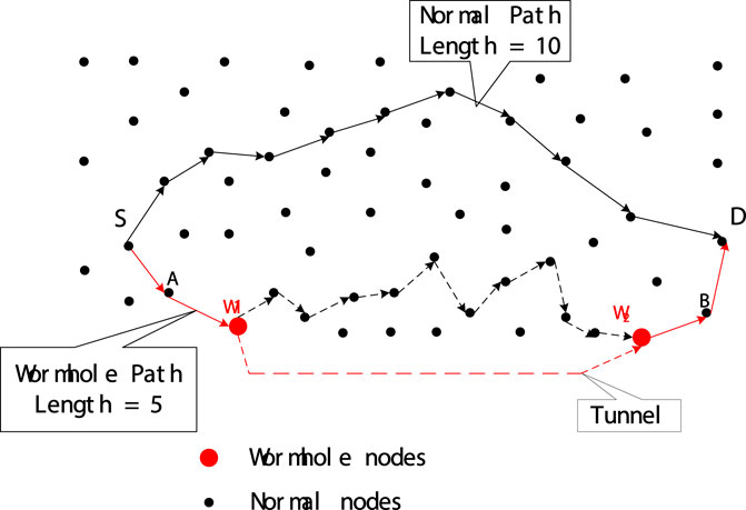
FIGURE 1. Scenario of wormhole attack.
In this paper, a new cluster-based scheme is proposed to prevent wormhole attacks in MANET. The structure of our paper is as below. The next section introduces related works. In Section 3, our new clustering algorithm is proposed to select cluster heads (CHs) that perform wormhole attack prevention. Section 4 introduces a detection method in detecting the presence of wormhole attacks in the network. Subsequently, Section 5 proposes a localization mechanism to identify wormhole nodes. Section 6 gives performance simulations. At last, our paper is summarized briefly in Section 7.
2 Related works
In (Garg et al., 2019), the authors introduce a wormhole attack detection system using machine learning which determines the behavior of mobiles in MANETs. This system uses the trace files produced by the simulator which consists of both normal and abnormal behavior of nodes. The obvious weakness of the method in this paper is the hug time cost to generate a set of data that will be used to learn the attack. The method based on Artificial Neural Network machining learning is not suitable for detecting wormhole attacks in the environment of MANET especially considering the hug collection cost of transmitted packets and training.
In (Krundyshev et al., 2018), the authors propose the approach to provide security for MANET and other types of transport relative networks using swarm algorithms of artificial intelligence. The proposed swarm algorithm is used to locate wormhole attack in MANETs. The algorithm in this paper uses Intelligent Water Drops (IWD) with trust model. Trust is the basic element in making a trusted mobile environment which promotes security in mobile networks. Trust value of neighbor node is calculated. Average value of the pheromone per unit calculates and then checks to the threshold value if exceeded node secure either not secure. The limitation of this paper is that parameters are re-initialized after each iteration of the IWD algorithm which leads to high cost in MANET.
In (Ahutu and El-Ocla, 2020), the authors describe a secure routing protocol using the lightweight multi-hop routing protocol called MAC Centralized Routing Protocol (MCRP). It uses concept of the time ratio threshold to locate wormhole attacks and malicious nodes. The authors assume that normal nodes are only responsible for data forwarding. The key point in the MCRP routing protocol is the implementation of centralized network intelligence to reduce the energy consumption while maintaining the consensus between nodes. Accordingly, it can detect wormhole attacks. However, some nodes may be incorrectly identified as wormhole nodes because they are located in prime locations for connections within the network.
To avoid the weaknesses of the above proposals, we propose our wormhole attack prevention scheme.
3 Preliminaries
Our mechanism is outlined below. First of all, the whole network is cutted into clusters. CHs are elected in corresponding clusters. Then, CH needs to perform a wormhole attack prevention scheme including a detection phase and a localization phase in each cluster. Therefore, three questions should be addressed (Adarsh et al., 2021): How to elect a CH for each community? (Ghugar and Pradhan, 2021)? How does CH detect the existence of a wormhole attack? (Tahboush and Agoyi, 2021)? How does CH identify wormhole nodes?
3.1 Preparatory work: Three parameters
First, to answer the first question mentioned above, a new clustering algorithm is proposed that uses the Analytic Hierarchy Process (AHP) (Raghav et al., 2022) to calculate the weight of every node in MANETs. The node having the largest nearby weight value is selected as the CH in the corresponding cluster. In this subsection, three parameters will be introduced to jointly determine the weight of each node, including relative stability (Sr), connectivity value (Cv), and forward exchange rate reciprocal (Rf). The first parameter Sr is evaluated in terms of the rate of change of the neighbors ′. The second parameter Cv is evaluated based on the value of distance to neighbors and the number of neighbors, also known as distance-considered connectivity. The third parameter Rf is evaluated based on the packet forwarding rate. In short, the nodes remain relatively stable or move slowly, the closer the neighbors, the lower the forwarding rate and the greater the chance of being selected as the CH. Conversely, a node with a fast moving speed, or a node with fewer and fewer neighbors, or a node with a higher forwarding rate, has a smaller chance of becoming a CH in the corresponding vicinity. The function of each parameter and the evaluation process are described below.
3.1.1 Relative stability (Sr)
The need for relative stability (Sr) needs to be explained. Consider the following scenarios (Adarsh et al., 2021): A node moves so fast compared to its neighbors that its connections and communications with other nodes are very brief. In this case, this node is of little use and should not be assigned important responsibilities (Ghugar and Pradhan, 2021). If a node with relatively fast mobility compared with its neighbors is selected as the CH, the cluster managed by this node will collapse quickly. Therefore, cluster reassociation must be performed, which greatly increases the overhead. Considering these situations, our scheme is to choose a relatively stable CH that can stay nearby for a longer time, rather than a node with high mobility. Therefore, a relative stability parameter is involved to compute the stability of each node.
The value of Sr for a node is evaluated based on changes in its neighborhood. As the parameter name implies, it is a relative value. Relative stability is defined as the stability compared to hop-on neighbors. In contrast to relative stability, absolute stability is the stability compared to some frame of reference such as a laboratory floor or road. Relative stability is more useful in terms of data transfer rates, given the frequent changes in topology in MANETs. It indicates whether a node is moving relatively fast or slow or even steady in its neighbors compared to its neighbors.
Our method uses graph theory (He et al., 2022) and similarity calculation method (Hu et al., 2022) to calculate the relative stability of every node. A network with nodes and links is a directed graph, G(t) = (V(t), E(t)), which is called a neighbor relationship graph, where V(t) = {v1, v2, … , vn} represents the set of participating nodes, E(t) = {e1, e2, … , em} represents the set of wireless links. If vi gets the data from vj, there is a directed edge e (i, j) between vi and vj. It means that vj is the neighbor of vi.
Vi(tj) and Vi(tj+1) are vectors, representing node vi within the transmission area of some consecutive two time points tj and tj+1Mobilenodesituation. Ei (tj) and Ei (tj+1) represent the wireless link situation of node vi in the transmission area of some two consecutive time points tj and tj+vector1. According to similarity theory (Jaccard index), the stability of nodes in the transmission region of node vi can be calculated by the average similarity value between Vi(tj) and Vi(tj+1) as shown in Eq. (1).
where θj is the angle between Vi(tj) and Vi(tj+1), and P is the number of time points at which Vi(tj) was observed. Snode (tj, tj+1) represents the similarity between the state of the neighboring situation of node
Similarly, the link stability between nodes in the transmission area of vi is computed by the average similarity value between Ei (tj) and Ei (tj+1) as shown in Eq. 2.
where θk is the angle between the two vectors Ei (tj) and Ei (tj+1), and P is the number of time points at which Ei (tj) is observed. Slink (tj, tj+1) represents the similarity of different link vectors in the transmission area of node vi at different time points, such as tj and tj+1. If Slink is larger, the angle between Ei (tj) and Ei (tj+1), ie θk will be smaller, which means Ei (tj) and Ei (tj+1), that is, the link within the transmission range of vi does not change dynamically at the time points of tj and tj+1.
At last, based on the similarity theory, relative stability of a node is computed using Snode and Slink as shown in Eq. 3.
where α is the weighting factor evaluated by Eq. 4.
The rationality of the setting of α is analyzed as follows.
• First of all, the filling-in of α does not change the property of the function of Sr in terms of increasing function or decreasing function, e.g., Sr is still a increasing function as the intersection of Vi(tj) and Vi(tj+1) or the intersection of Ei (tj) and Ei (tj+1) increases.
• α is always larger than 1 − α, so the effect of Snode is enhanced purposely by the weighting in Equation. This is due to the consideration that the variation of neighbors is more important than that of links, since link is more frangible in MANETs.
The main feature of MANET is its dynamic topology, where nodes change positions randomly. CH should change as little as possible while moving. Therefore, a node that moves slowly compared to its neighbors is chosen as the CH; otherwise, the cluster may become corrupted. Therefore, nodes with larger Sr are better suited to play the CH role.
An illustrative case is as below. In Figure 2, two groups of nodes at time points tj and tj+1 are Vi(tj) = {va, vb, vc, vd, ve} and Vi(tj+1) = {va, vb, vc, ve, vf}; the corresponding two sets of links are Ei (tj) = {eab, ebc, ecd, ede} and Ei (tj+1) = {eab, eac}, respectively.
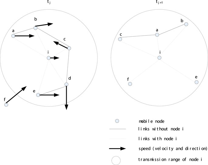
FIGURE 2. Illustration for relative stability.
3.1.2 Connectivity value (Cv)
The second parameter is computed using the number of node′s neighbors and their distance values from different neighbors, named the connectivity value (Cv), as shown in Eq. 5.
where C(i) is the connectivity degree that stands for the neighbor counts of vi. D(i) is the distance value sum between vi and its neighbors calculated by Eq. 6.
where N is the number of nodes in V that stands for the neighbors of vi. Node i is a neighbor of node j within the transmission range of j. (xi, yi) and (xj, yj) are the coordinates of vi and vj respectively.
If a node has more neighbors, the node is in a more important position. Therefore, nodes with greater connectivity should be more likely to be selected as CHs. If a CH has distant members, more power is needed when nodes are far away. Therefore, nodes with a smaller sum of distances are more popular than nodes with a larger sum of distances. Nodes with a big number of neighbors and a small distance from their neighbors have a higher chance to be elected as a CH, which can minimize node separation and enhance the stability of the cluster. Figure 3 shows an illustrative example.
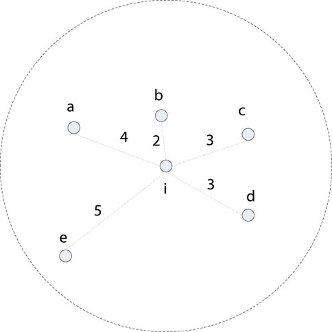
FIGURE 3. Illustration for connectivity value.
3.1.3 Reciprocal of forward rate (Rf)
Rf is evaluated based on the packet forwarding rate, as shown in Eq. 7. It indicates whether the node violates the backoff mechanism (?) specified by DCF in 802.11 so that they have a higher chance of blocking the wireless channel, or the node performs a wormhole attack, reducing the number of hops of the routing path to capture passing packets. It stands for the remaining battery power since frequent packet forwarding enhances the battery drain rate.
where Fr represents the forward exchange rate.
3.2 Election of clusterhead
The calculation of the three parameters Sr, Cd and Rf is introduced. The weight of each node will then be calculated by considering these three parameters. To make CH election decisions in an organized way, the AHP method can be used to decompose the decision into the following four steps to generate priorities.
• Step 1: Define the issue.
The decision issue is to elect an appropriate node by considering the corresponding weight value as the cluster head in one-hop neighborhood in the MANETs.
• Step 2: Build a decision hierarchy from top to the goal, afterwards from the broad perspective, through middle to the lowest level. The middle level refers the criteria subsequent elements depend on. The lowest level refers a set of alternatives
Figure 4 shows structuring the problem into a hierarchy. The overall goal of selecting a suitable CH is at the top of the hierarchy. Subsequent levels representing primary criteria are called secondary objectives. The three secondary goals are Sr, Cv and Rf. At last, alternatives are put at the bottom of the hierarchy to evaluate CH election.
• Step 3: Make a group of pairwise comparison matrices.
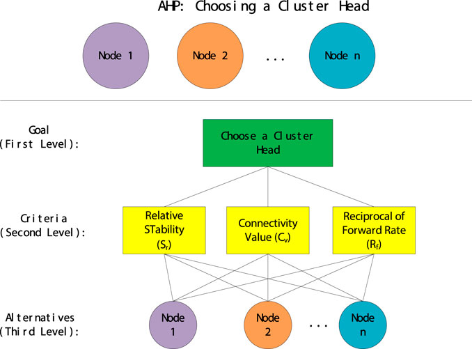
FIGURE 4. Hierarchical structure.
For comparison, it requires a numerical scale that indicates how many times more dominant one element than another on the criterion. Table 1 refers the scale.

TABLE 1. Fundamental scale of absolute numbers.
The reciprocal matrix is constructed by comparing each criterion pairwise with another criterion present under the highest target. The values of the pairwise comparison matrix are provided by answering questions that gain more preference and the degree of preference. The criteria matrix A gives pairwise comparisons of the three criteria against the highest target, as shown below. The value aij represents the preference strength of the ith criterion over the jth criterion. In Table 1, a basic one to nine scale is used to express the strength of preference based on experience and knowledge. The A matrix is explained in Eq. 8 below.
A can be normalized to a normalized vector matrix Anorm by using mean normalization of row vectors, as shown in Eq. 9.
where k is the number of criteria. In our mechanism, three parameters are named the criteria to evaluate weight value of every node, so k is equal to 3.
Then, by normalizing the mean of the row vector, the normalized vector
Check all pairwise comparison matrices for consistency. Since people′s random judgment matrix can be prone to judgment errors, such judgment errors can be detected by the consistency ratio (CR) that is named as the ratio of consistency index (CI) to random index (RI). CI is calculated by Eq. (11) using standard matrix C as a instance. Consistency is considered after computing the weights for each criterion.
where n refers the element counts compared in criteria matrix A, here it is 3. λ is evaluated by Eq. 12.
where μi is the consistency vector that is computed by Eq. 13.
where wi is the weight factoring of each criterion calculated by the aforementioned Eq. 10.
Finally, the consistency ratio (CR), the ratio between CI and RI, can be obtained as shown in Eq. 14. RI as shown in Table 2.
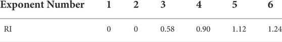
TABLE 2. Random index.
When CR
• Step 4: Use the priorities made by the comparisons to weigh the priorities in the next level. Repeat it for each element. Then, for every element in level below increase its weighed values and get its global priority. Repeat this weighing process until the final priorities of the alternatives in the bottom most level are completed.
Calculate local weights for every criterion and alternative. After computing the weight of every criterion, the weight of each node should be computed in the same way. It needs to compare nearby nodes from every angle of every criterion. Therefore, the following three matrices can be obtained, namely
4 Detection phase for detecting wormhole attacks
Through the clustering algorithm mentioned earlier, MANET is divided into several clusters, as shown in Figure 5. An overlay is took in this paper tha is a virtual layer composed by CHs and gateways (GWs). CH needs to be responsible for the corresponding cluster and implement our wormhole attack prevention scheme. In the figure, the corresponding CHs are marked as CH1, CH2, CH3 and CH4 respectively. The role of gateways is to connect clusters and ensure data transmission between clusters, and can be divided into conventional gateways (RGW) and distributed gateways (DGW). An RGW is defined as a node in the overlapping region of two adjacent clusters, such as node RGW1. DGWs reside in two adjacent clusters respectively and can communicate directly with each other, such as nodes DGW1 and DGW2.
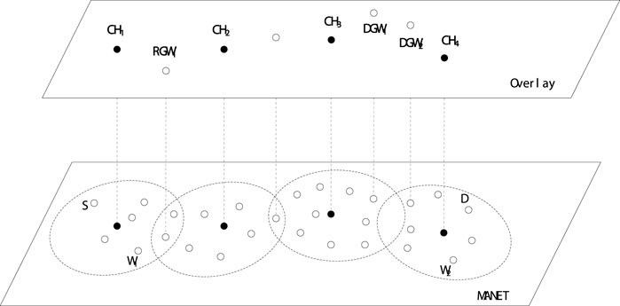
FIGURE 5. Clusters and overlay layer with clusterheads and gateways.
Similar to AODV, the RREQ is broadcasted by source S to initiate the routing request process. Compared to AODV which uses a 2-tuple (source node IP, broadcast ID) to identify whether a RREQ is duplicated, in our scheme, a 3-tuple (source node IP, broadcast ID, first node IP) is used. The first node is named as a node located in the one-hop neighborhood of the source, sya the number of hops between the first node and the source is one. Triplets bring several benefits. One is to mitigate broadcast storms caused by duplicate RREQs, since intermediate nodes do not handle duplicate RREQs that go through the same first node. Another benefit brought by the first node mechanism is that multiple loop-free paths can be maintained, which can reduce the frequency of restarting the routing request process.
The process of node receiving RREQ is shown in Figure 6. Duplicate RREQs are simply discarded. The node that receives the RREQ will perform a process from the following two candidate actions, depending on if it is a target or an intermediate node.
• If the node decides that it is an intermediate node, i.e. not the destination node, it checks the hop count extracted from the RREQ. If the RREQ is greater than the number of hops in the corresponding entry in the routing table, RREQ is dropped. Or else it puts in a new entry in the routing table to make multiple routing paths. In short, all duplicate RREQs are discarded directly, and RREQs with smaller hop counts are used for intermediate nodes to create reverse paths for the following RREPs.
• If the node decides that it is the destination, it verifies if the sequence number of RREQ given by the source is bigger than the sequence number of any entry in the routing table. Or else, the destination directly drops the RREQ; if it is, it means that the RREQ has expired, and the destination node will reply RREP for each RREQ on the reverse routing path. No matter how many RREQs the destination node receives, it will reply RREPs to those corresponding RREQs, unless the sequence number of RREQ is smaller than that in the destination node′s routing table. In Figure 7, when RREP reaches the source node, it maintains multiple routing paths.
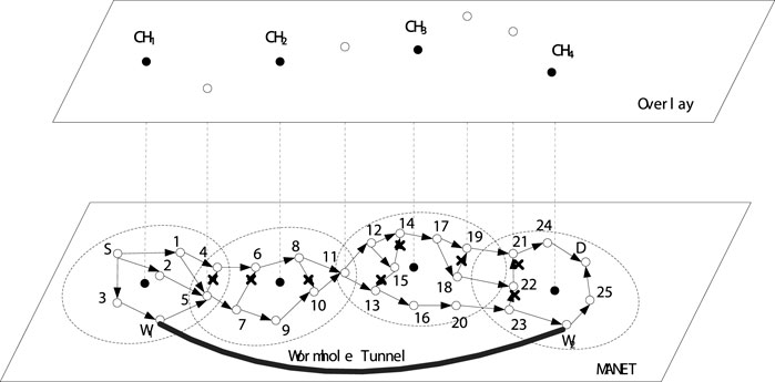
FIGURE 6. Routing request process.
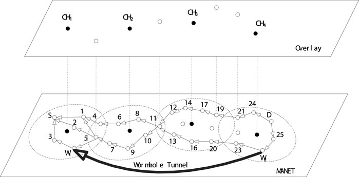
FIGURE 7. Routing reply process.
In our scheme, it is regulated that only the destination node has the permission to reply RREP to RREQ. Compared with AODV, where any intermediate node that owns the path to the destination node can reply RREQ with RREP, in our scheme, it is forbidden. In AODV case, the detection of wormhole attacks cannot be guaranteed, since wormhole nodes may not be involved in the routing path with the intermediate node that reply the RREP. Conversely, in our scheme, all nodes including wormhole nodes are required to participate into the routing process in order to expose the wormhole nodes’ existence. In routing request process, every intermediate node lists the hop count to the source when the RREQ passes through the routing path, denotes as HopRREQ. On the other hand, in routing reply process, each intermediate node records its hop count value to the destination node when the RREP passes through the reversed routing path, denotes as HopRREP as shown in Figure 7.
As shown in Figure 6, the RREQ retransmitted by node five is dropped by node 4, since the RREQ′s first node is node one which is the same with the RREQ received by node four from node 1. Thus, the broadcast storm caused by the potential loop among node 1, node four and node five is avoided. As it is assumed that the node W1 and W2 are wormhole nodes that collude with each other, after receiving the RREQ, the wormhole node W1 will encapsulate the RREQ and deliver it to its partner W2 via the tunnel between them, and then the wormhole node W2 can receive the RREQ after the decapsulation. Thus, after the establishment of the routing paths by the routing reply process as shown in Figure 7, the routing path with the wormhole nodes W1 and W2 is definitely much smaller than the other regular routing paths.
CH does not participate in the routing request process and routing response process, but is defined to only monitor the abnormal occurrence of the cluster. After the routing path is established, each intermediate node reports the values of HopRREQ and HopRREP to the corresponding CH, as shown in 8. You will see the cluster monitored by CH1 and the same process will happen on other clusters as well. Each CH then calculates the hop value (Hop = HopRREQ + HopRREP) of the routing path to each node in the cluster to find the maximum hop value (Hopmax). And the minimum hop value (Hopmin). If the gap (G) between two hop count values is greater than a predefined threshold (Hopth), CH determines that there is a wormhole node in the cluster. The size of the threshold Hopth is given based on the density and the scope of the MANET. If the network is dense and large, a relatively small value is given to the threshold Hopth. Otherwise, if the network is sparse and small, assign a relatively large value to the threshold Hopth. The way for computing threshold Hopth is as Eq. 18.
In our scheme, it is stipulated that only the destination node has the right to reply RREP to RREQ. In contrast to AODV, any intermediate node with a path to the target node can reply to RREQ using RREP, which is forbidden in our scheme. In the case of AODV, detection of a wormhole attack is not guaranteed, because wormhole nodes may not participate in routing paths and intermediate nodes that reply to RREPs. In contrast, in our scheme all nodes are required to participate in routing process to expose the existence of wormhole nodes. In routing request process, each node records hop counts from RREQ to the source when it passes through the routing path named as HopRREQ. On the other hand, in the route reply process, while RREP passes through the reverse routing path, each node records hop counts to the destination, which is named as HopRREP, like ??
As in Figure 6, RREQ resented by node five is dropped by node 4, because the first node of RREQ is node 1, which is the same as the RREQ received by node four from node 1, thus broadcast storms caused by potential loops between Node 1, Node 4, and Node five are avoided. Since it is assumed that the nodes W1 and W2 are wormhole nodes that collude with each other, the wormhole node W1 will encapsulate the RREQ after receiving the RREQ and pass it to its partner W2 through the tunnel, and then the wormhole node W2 can receive the decapsulated RREQ. Therefore, after the routing path is established by the routing reply process shown in Figure 7, the routing paths of the wormhole nodes W1 and W2 must be much smaller than other conventional routing paths.
It is legitimate that the CHs do not participate in routing request process and also routing response process, but is only responsible for monitoring the abnormal situation in the corresponding cluster. After the routing path is established, each intermediate node reports its own HopRREQ and HopRREP values to its corresponding CH, as shown in Figure 8, in which only the first The details in this show the cluster monitored by CH1, and the same process happens in other clusters. After that, each CH computes the Hop count value of the routing path in its cluster (Hop = HopRREQ + HopRREP), and obtains the maximum Hop count value (Hopmax) and the minimum hop value (Hopmin). If the gap (G) between the two Hop count values is greater than a predefined threshold (Hopth), then CH judges that there are wormhole nodes in its cluster. The size of the threshold Hopth is given based on the density and scale of the MANET. If the network is dense and large, the threshold Hopth is given a relatively low value; otherwise, if the network is sparse and large in scale small, assign the threshold Hopth to a relatively large value. The method to compute the threshold Hopth is in Eq. 18.
where D is the distance between the start and end nodes. R is the average distance of each hop and is calculated by the relationship between density and number of nodes in Eq. 19. m is the length of square side. n is the number of nodes in the network. In our scheme, the threshold Hopth is set to 5, which means that if the gap (G) between Hopmax and Hopmin is greater than 5, then the CH completes in error. During the vulnerability detection phase, the presence of a wormhole attack is locally detected by the CH, and the possible candidates for one of the wormhole nodes are narrowed down to that cluster member.

FIGURE 8. Clusterheads monitor the corresponding clusters.
5 Location phase for locating wormhole nodes
After CHs detects that there is a wormhole attack in the corresponding cluster, it triggers the wormhole node localization phase. Each node in each cluster needs to report its one-hop neighbor node list to the corresponding CH. One-hop neighbor information can be obtained through beacons (HELLO messages). By means of a watchdog mechanism, forging neighbor lists can be avoided. Finally, CH can collect a list of neighbor nodes for each node. After that, CH performs the following steps.
• Step 1: If neighbors of a member node are all in the cluster, the CH considers the member node to be a legitimate node. CH continues to check the remaining member nodes until it finds a node with neighbors that are not in the cluster, then CH proceeds to step 2.
• Step 2: After identifying a neighbor node in the neighbor list that is not in the corresponding cluster, the CH sends a topology check (Topology Check, TC) message to the neighbor CH of the neighbor cluster through the GW to track the neighbor node. Indicates that in addition to the responsibility of locally monitoring each cluster, another responsibility of the CH is to verify the local topology through TC messages.
• If an adjacent node of the member node in the previous cluster is found in the adjacent cluster, the adjacent CH replies to the TC message with a topology check reply (TCR) message to confirm the legitimacy of the member node in the previous cluster.
• If no neighbor of the member node in the previous cluster exists in the neighbor cluster, the neighbor CH does not reply to the TCR.
• Step 3: After waiting for a predetermined time, if the CH that sent the TC does not receive any TCR, the corresponding member node is regarded as a node forging adjacent nodes, that is, a wormhole node.
For example, as shown in Figure 9, node W1 claims that node W2 is an adjacent node, satisfying the definition of a wormhole attack. However, the corresponding clusterhead CH1 cannot find node W2 in its cluster, so clusterhead CH1 sends a TC message to its neighboring cluster through the GW. The adjacent CH, namely CH2, also cannot find the existence of node W2. Therefore, after waiting for some time, CH1 cannot receive any TCRs from its neighboring CHs, so CH1 identifies node W1 as a wormhole node in its cluster. The positioning process of W2 is the same as that of the wormhole node W1. After the location of the wormhole node W1, CH1 sends an alert message through the overlay to warn the rest of the network to expose the wormhole node.
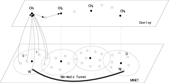
FIGURE 9. Location phase for locating the wormhole nodes.
The reasons for dividing worm attack prevention into two phases, the detection phase and the localization phase, are as follows. The goal is to apply precautions against worm attacks locally rather than globally (i.e. in each cluster). The discovery phase is performed only on each cluster, ensuring locality. The locality of our plans can significantly reduce overhead and ensure plan scalability, especially in dense and large MANETs. For the localization stage, we separate the localization and detection stages because the localization does not reach 100%. However, since only TC messages and TCR messages are transmitted between adjacent clusters even in the positioning phase, the overhead does not increase much.
6 Simulation results
In this section, the performance is simulated. The network consists of 50 nodes in random.
In Figure 10, if it has no wormhole attack in the network, our scheme hardly degrades the network throughput. When a wormhole attack occurs on the network and the traffic load is less than 650 Kbps, the performance of our mechanism is unaffected compared to the one without wormhole attack. However, under the wormhole attack, using the AODV protocol, the delivery rate is only about 52% regardless of the traffic load. This is because about half of the traffic goes through the path of the wormhole link. When using our scheme, wormhole attacks can be detected and wormhole nodes can be located, so the performance is almost the same as without wormhole attacks. The performance of our scheme gradually degrades when the traffic load exceeds 750 Kbps. This is caused by the additional overhead involved by the scheme. It is concluded that our scheme is sufficient to prevent wormhole attacks when the traffic load is moderate, i.e., the maximum traffic load is around 750 Kbps.
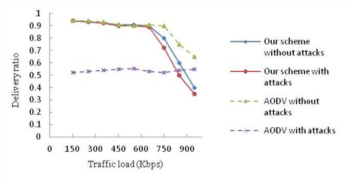
FIGURE 10. Packet delivery ratio vs traffic load.
The proposed scheme can not only detect wormhole attacks, but locate wormhole nodes. The scheme also considers more parameters into the calculation of node’s weight. The purpose of including more parameters is to enhance the cluster node’s stability and reduce the frequencies of reelection of the cluster node. This scheme also chooses more important and rightful parameters in order to make the balance between the rightness of the selection of cluster node and efficiency of weight calculation and exchange.
Furthermore, as the time goes by, the performance of our scheme is not decreases. In our scheme, each CH takes charge of each cluster so that the process of attack detection is performed locally, by which the overhead can be reduced. Therefore, the performance of our scheme almost keeps stable.
7 Conclusion
In this paper, a new cluster-based scheme is proposed to combat wormhole attacks in MANET. Performance simulations confirm the usability and efficiency of our scheme. In our future work, we will compare our scheme with more relevant ones. Furthermore, we plan to port the proposed scheme to prevent other types of attacks.
Data availability statement
The original contributions presented in the study are included in the article/supplementary material, further inquiries can be directed to the corresponding author.
Author contributions
WL, first author, propose the main scheme in this paper. ZC, XY and XZ are co-authors who do the paper work and simulations.
Funding
This research was supported by National Social Science Fund Project through the research on construction mode of Yangtze River Delta regional innovation and entrepreneurship ecosystem in the digital economy era (21BGL059), and also supported by Key Project of Zhejiang Soft Science Research Program through Research on the Construction Thought of Zhejiang Digital Technology Innovation Center (2019C25034).
Conflict of interest
The authors declare that the research was conducted in the absence of any commercial or financial relationships that could be construed as a potential conflict of interest.
Publisher’s note
All claims expressed in this article are solely those of the authors and do not necessarily represent those of their affiliated organizations, or those of the publisher, the editors and the reviewers. Any product that may be evaluated in this article, or claim that may be made by its manufacturer, is not guaranteed or endorsed by the publisher.
References
Adarsh, A., Tamang, T. L., Pradhan, P., Singh, V. K., Sen, B., and Sharma, K. (2021). Delay-based approach for prevention of rushing attack in MANETs. Lect. Notes Netw. Syst. 281, 125–138. doi:10.1007/978-981-16-4244-9_10
Afzal, Z., and Kumar, M.. Security of vehicular ad-hoc networks (MANET): A survey. J. Phys. Conf. Ser. 1427, 0120152020.
Ahutu, O. R., and El-Ocla, H. (2020). Centralized routing protocol for detecting wormhole attacks in wireless sensor networks. IEEE Access, 63270–63282.
Garg, S., Singh, A., Kaur, K., Singh Aujla, G., Batra, S., Neeraj Kumar, M. S., et al. (2019). Edge computing-based security framework for big data analytics in VANETs. IEEE Netw. 33 (2), 72–81. doi:10.1109/mnet.2019.1800239
Ghugar, U., and Pradhan, J. (2021). Survey of wormhole attack in wireless sensor networks. Comput. Sci. Inf. Technol. 2 (1), 33–42. doi:10.11591/csit.v2i1.p33-42
He, W., Lu, M., Zheng, Y., and Xiong, N. N. (2022). Research on graph structure data adversarial examples based on graph theory metrics. Cham: Springer.
Hu, X., Hu, Z., Jiang, J., Xue, W., Hu, X., and Xu, X. (2022). Character embedding-based bi-lstm for zircon similarity calculation with clustering. Earth Sci. Inf. 15 (3), 1417–1425. doi:10.1007/s12145-022-00847-y
Krundyshev, V., Kalinin, M., and Peter, Z. (2018). Artificial swarm algorithm for MANET protection against routing attacks. IEEE Industrial Cyber-Physical Systems (ICPS), May 2018, 795–800. doi:10.1109/ICPHYS.2018.8390808
Raghav, L. P., Kumar, R. S., Raju, D. K., and Singh, A. R. (2022). Analytic Hierarchy Process (AHP) – swarm intelligence based flexible demand response management of grid-connected microgrid. Appl. Energy 306, 118058. doi:10.1016/j.apenergy.2021.118058
Sarhan, S., and Sarhan, S. (2021). Elephant herding optimization ad hoc on-demand multipath distance vector routing protocol for MANET. IEEE Access 9 (99), 39489–39499. doi:10.1109/access.2021.3065288
Tahboush, M., and Agoyi, M. (2021). A hybrid wormhole attack detection in mobile ad-hoc network (MANET). IEEE Access 9, 11872–11883. doi:10.1109/access.2021.3051491
Keywords: analytical hierarchy process, cluster, smart grid, wormhole, AHP
Citation: Liu W, Chen Z, Yu X and Zhou X (2022) A cluster-based approach against wormhole attacks in MANETs among smart grid. Front. Energy Res. 10:1017932. doi: 10.3389/fenrg.2022.1017932
Received: 12 August 2022; Accepted: 29 August 2022;
Published: 27 September 2022.
Edited by:
Chunhe Song, Shenyang Institute of Automation (CAS), ChinaReviewed by:
Xinli Wang, Shandong University, ChinaWenhuan Wang, Zhejiang University of Technology, China
Copyright © 2022 Liu, Chen, Yu and Zhou. This is an open-access article distributed under the terms of the Creative Commons Attribution License (CC BY). The use, distribution or reproduction in other forums is permitted, provided the original author(s) and the copyright owner(s) are credited and that the original publication in this journal is cited, in accordance with accepted academic practice. No use, distribution or reproduction is permitted which does not comply with these terms.
*Correspondence: Xue Zhou, eHVlemhvdWFwcGxpY2F0aW9uQDEyNi5jb20=