 Zhuang Xu
 Jun Liang
 Yanxun Guo
 Yaoqiang Wang
- 1School of Electrical Engineering, Zhengzhou University, Zhengzhou, China
- 2School of Engineering, Cardiff University, Cardiff, United Kingdom
DC circuit breakers (DCCBs) are the critical equipment to isolate faults in high-voltage DC grids. The improvement of interruption performances of capacitor-based DCCBs (C-DCCBs) has been widely researched. However, in previous papers, the adaptive reclosing of C-DCCBs is less considered and requires further research. In this paper, a novel C-DCCB with adaptive reclosing ability is proposed. The interruption and adaptive reclosing processes of the proposed C-DCCB are presented. The fault current is interrupted by charging the internal capacitor to a voltage higher than the system voltage. The fault property identification is key to adaptive reclosing and is achieved using the capacitor discharge characteristic. The parameter designs are analyzed to guarantee successful interruptions, and the identification criteria are proposed to serve the adaptive reclosing. On the one hand, the proposed C-DCCB has good interruption performances; on the other hand, an adaptive reclosing strategy is designed for the proposed C-DCCB to restore the power transmission whereas avoiding a second fault shock, which is the main contribution of this paper. Finally, the interruption and adaptive reclosing performances of the proposed C-DCCB are validated using PSCAD/EMTDC simulations.
1 Introduction
High-voltage DC (HVDC) grids have great application potential in renewable energy integration, island power supply and AC grid interconnection (Hertem and Ghandhari, 2010)- (An et al., 2017). However, after a DC fault occurs, the DC fault current quickly increases and the DC voltage rapidly drops, which seriously affects the safe and stable operation of HVDC grids. DC circuit breakers (DCCBs) can soon isolate the fault area and maintain the normal operation of the nonfault area. Traditionally, DCCBs are divided into mechanical, solid-state and hybrid DCCBs (Bucher and Franck, 2016)- (Chen et al., 2021). Several mechanical DCCBs use semiconductors such as thyristors to improve the interruption performance, obscuring the boundary between mechanical and hybrid DCCBs (Wen et al., 2018)- (Wu et al., 2020a). In this paper, DCCBs that interrupt the fault current by semiconductors with turn-off ability are called semiconductor-based DCCBs (S-DCCBs); DCCBs that interrupt the fault current by charging the internal capacitor to a voltage higher than the system voltage are called capacitor-based DCCBs (C-DCCBs).
In S-DCCBs, the main breaker (MB), which is composed of insulated-gate bipolar transistors (IGBTs) or integrated gate commutated thyristors (IGCTs), can interrupt the fault current. In (Hafner and Jacobson, 2011; Hassanpoor et al., 2015; Wen et al., 2016; Jovcic et al., 2019), S-DCCBs conduct the system current with small conduction losses during a normal state. During interruptions, the system current is commutated into the MB and then interrupted by the MB. S-DCCBs have attracted considerable attention because of good interruption performances. In China, S-DCCBs with different topologies have been applied to the Zhoushan DC project and Zhangbei DC grid project, respectively (Jovcic et al., 2019). However, the interruption capacity of S-DCCBs is limited by the turn-off capacity of IGBT and IGCT, and IGBT and IGCT bring high construction costs.
For C-DCCBs, the system current is commutated into the internal capacitor during the interruption. It gradually decreases to 0 after the capacitor is charged to a voltage higher than the system voltage. C-DCCBs usually use semiconductors without turn-off ability to save the construction cost, such as thyristors and diodes. C-DCCBs with different topologies in China have been applied to the Zhangbei DC grid project and the Nan’ao DC grid project, respectively (Liu, 2019)- (Chen et al., 2018). Many topologies have been proposed to improve the C-DCCB performances regarding bidirectional interruption, interruption speed, pre-activation ability, etc. The C-DCCB in (Wu et al., 2020b) achieves bidirectional current commutation using bridge-type branches. In (Jamshidifar and Jovcic, 2018), the C-DCCB uses fast thyristors to quickly interrupt large fault currents. In (Sima et al., 2019), the capacitor is inserted into a bridge composed of spark gap switches, and this topology guarantees that the C-DCCB can consecutively interrupt the fault current. The pre-activation of DCCB achieves that the DCCB operation time overlaps with the protection time, which effectively reduces the fault interruption time (Hafner and Jacobson, 2011). However, the C-DCCBs in (Chen et al., 2018; Jamshidifar and Jovcic, 2018; Liu, 2019; Sima et al., 2019; Wu et al., 2020b) do not have the pre-activation ability. For C-DCCBs in (Wu et al., 2019) and (Guo et al., 2020), the thyristors in the MB can temporarily conduct the load current, thus achieving the pre-activation ability. In (Augustin et al., 2021), a C-DCCB family consisting of one unidirectional and six bidirectional concepts is presented, and all concepts have the pre-activation ability. Nevertheless, the reclosing of C-DCCBs is not considered in (Liu, 2019)- (Augustin et al., 2021).
Considering that most overhead line faults are transient, the DCCB should reclose in time to restore the power transmission after isolating (Wang et al., 2203). However, in case of a permanent fault, the direct reclosing will bring a second fault shock, which is harmful to the HVDC grid. To solve this problem, the permanent and transient faults should be discriminated, and the DCCB only reconnects the HVDC grid to the isolated line when the fault is transient, which is called adaptive reclosing.
The fault property identification is key to the adaptive reclosing strategy. Because the permanent and transient faults result in different boundary conditions, the fault property can be identified according to the traveling wave characteristics (Wang et al., 2203)- (Mei et al., 2021). In (Wang et al., 2203), the voltage pulse is produced by the hybrid MMC on the healthy pole. However, considering the construction and conduction cost, the half-bridge MMC is more attractive than the hybrid MMC for HVDC grids. In (Song et al., 2019)- (Zhang et al., 2020), the voltage pulse is injected into the fault line by controlling the MB of S-DCCBs. The MMC and S-DCCB are simultaneously controlled to produce the voltage pulse in (Yang et al., 1123). In (Mei et al., 2021), the voltage pulse comes from the energy absorption module of S-DCCB. In (Li et al., 2020), the HVDC grid charges the fault line through the arrester of S-DCCB, and the fault property is identified using the fault line voltage. In (Pei et al., 2019), the fault property can be identified using the fault current, and the fault current is limited because the MB modules are sequentially turned on. However, the methods in (Wang et al., 2203)- (Pei et al., 2019) do not consider the C-DCCBs.
For C-DCCBs, most previous papers consider the direct reclosing and the consecutive interruption ability rather than the fault property identification is focused on. For example (Sima et al., 2019),- (Augustin et al., 2021) use different methods to quickly restore the interruption ability of C-DCCBs before the direct reclosing. Nevertheless, the fault property identification and adaptive reclosing of C-DCCBs are worth studying to improve the reclosing performance. In (Wen et al., 2021), for HVDC grids adopting C-DCCBs, the fault property is identified by comparing the residual voltages at two ends of the isolated fault line. However, this method only applies to symmetrical monopole DC systems and requires long-distance communication. In (Torwelle et al., 2021), a grounded branch is added to the C-DCCB, which enables the internal capacitor charges the fault line, and the fault property is identified using the line voltage. However, the capacitor may need to charge the fault line multiple times, which obviously increases the reclosing time.
Although several C-DCCBs with good interruption performances have been proposed, the C-DCCB with adaptive reclosing ability needs further research. In this paper, a novel C-DCCB is proposed to serve HVDC grids. On the one hand, the proposed C-DCCB achieves good interruption performances; on the other hand, it has the ability of adaptive reclosing, which is the main contribution of this paper. The adaptive reclosing ability avoids the second fault shock in case of permanent faults and the voltage oscillations in case of transient faults. The paper is structured as follows. Section 2 describes the topology and operation of the proposed C-DCCB. Section 3 analyzes the parameter design and fault property identification. Section 4 shows the simulation results, which validate the performance of the proposed C-DCCB. Finally, Section 5 concludes this paper.
2 Proposed DC circuit breaker
2.1 Topology of the proposed C-DCCB
As shown in Figure 1, the proposed C-DCCB contains the main conductor (MC), MB, energy absorber (EA) and precharge branch. The MC is composed of a fast disconnector (FD) and a load commutation switch (LCS), and the LCS only endures the commutation voltage. The MB is composed of an inductor L, capacitor C, diodes D1–D2, and thyristors T1–T4. The EA is composed of an arrester and diode D3. The precharge branch is composed of a resistor R1 and thyristor T5. Both sides of the C-DCCB are equipped with residual current breakers (RCBs). The RCB can interrupt residual DC currents of up to 10 A, and the interruption time is 30 ms. After a current zero occurs, the FD can restore its dielectric strength within a few milliseconds to withstand the peak transient interruption voltage (TIV). In practical engineering, the FD can be composed of several vacuum circuit breakers to achieve operation performance (Shi et al., 2015).

FIGURE 1. Topology of the capacitor-based DC circuit breaker.
To clarify the operation processes, the current curves in C-DCCB during interrupting fault currents and reclosing with transient faults are shown in Figure 2, where is, imb, ifd, ic and iar are the currents of the DC system, MB, FD, capacitor C and arrester, respectively. The reference directions of currents and capacitor voltage uc are marked in Figure 1. During operations, the main switching events and time labels are given in Figure 2.
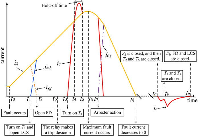
FIGURE 2. Current curves during interrupting fault currents and reclosing with a transient fault.
2.2 Operation processes of the C-DCCB
2.2.1 Capacitor precharge
Initially, the HVDC grid precharges the capacitor C by turning on T1, T2 and T5, and the current path is shown in Figure 3A. After the capacitor voltage uc is charged to the system voltage, T1, T2 and T5 naturally turn off. Because of the leakage discharge, uc slowly decreases during the normal state. Once uc decreases to a preset value, T1, T2 and T5 are turned on to precharge the capacitor. Thus, uc is always no less than the preset value during the normal state.
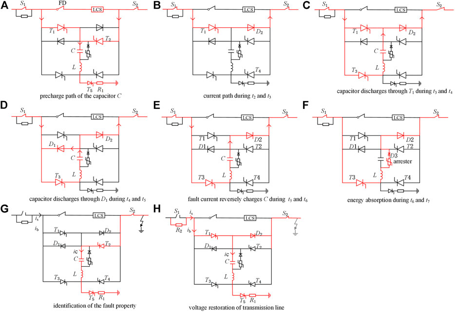
FIGURE 3. Operation procedures of the C-DCCB.
2.2.2 Current commutation
During the normal state, the MC conducts the load current with small conduction losses. Considering the pre-activation strategy, once the protection detects a potential fault at t = t1, the C-DCCB commutates the current into the MB by turning on T1 and turning off the LCS. At t = t2, ifd decreases to 0, and the FD begins to open. After that, the current path in the C-DCCB is shown in Figure 3B. If the protection decides not to interrupt the current at t = tp, the C-DCCB successively closes the FD and LCS; thus, the current naturally commutates into the MC, and the thyristor T1 turns off naturally after the current of T1 is smaller than the holding current; Otherwise, the C-DCCB performs the following interruption operations.
During t1–tp, the voltage drop in the C-DCCB is equal to the on-state voltages of T1 and D2; thus, the disturbance caused by the pre-activation is insignificant. By pre-commutating the system current from the MC into the MB, the C-DCCB operation time overlaps with the protection time. Thus, the pre-activation effectively reduces the fault clearing time.
2.2.3 Capacitor discharge
As shown in Figure 3C, during t3 and t4 the system provides the fault current to the fault point through S1, T1, D2 and S2. At the same time, the capacitor discharges through the following loop: C—T1—T3—L. As shown in Figure 3D, after ic exceeds the fault current at t = t4, T1 is reversely blocked, and the discharging loop is changed as: C—D1—T3—L. After ic decreases to the fault current at t = t5, D1 is reversely blocked, and T1 begins to endure the forward voltage stress, as shown in Figure 3E. To reliably turn off T1, the time interval between t4 and t5, which is the reverse-bias time of T1 and marked as tR, should be greater than the turn-off time tq. The turn-off time tq, which can be found in the datasheet, is the minimum reverse-bias time to ensure the turn-off of the thyristor (Technical Information, 2012).
During t2 and t5, the voltage drop in the C-DCCB is rather small compared with the system voltage. After t = t5, the voltage drop in the C-DCCB is approximately equal to the capacitor voltage and quickly charged to the system voltage. We mark the FD operation time as tFD. The value of t3 should meet the following two constraints: 1) t3 should not be earlier than tp, and 2) the FD recovers its dielectric strength at t = t2+ tFD, which time instant should be earlier than t5 to avoid the interruption failure. Considering that the interval between t3 and t5 is greater than tq, these two constraints can be satisfied when t3 is selected as:
2.2.4 Energy absorption
After the capacitor is charged to the arrester reference voltage, the fault current commutates into the EA and gradually decreases, as shown in Figure 3F. The arrester releases the residual energies stored in the system, and the peak TIV usually is limited to 1.5 times the system voltage. After the fault current decreases to 10 A, S1, and S2 are opened to isolate the fault totally. After the isolation, the capacitor voltage uc is opposite to its initial state.
2.2.5 Adaptive reclosing
To guarantee that the DC line recovers its insulation characteristic, the reclosing is usually hundreds of milliseconds later than the isolation (Yang et al., 1123). After receiving the adaptive reclosing command, the C-DCCB closes S2 and turns on T2 and T5. If the fault is permanent, the capacitor C significantly discharges through the following loop: C—L—T5—R1—fault point—S2—T2, as shown in Figure 3G. If the fault is transient, the capacitor slightly discharges through the equivalent grounded capacitance of the DC line.
After identifying the permanent fault, S2 is opened to isolate the fault when the discharging current is smaller than 10 A. After identifying the transient fault, the C-DCCB turns on T1 and T5; thus, the capacitor C and the DC line are charged to the system voltage, as shown in Figure 3H; after that, the C-DCCB successively closes S1, FD and LCS, and the reclosing is completed.
After reclosing the C-DCCB located on one side of the DC line, if the fault is transient, the line voltage is close to the system voltage; otherwise, the line voltage is much less than the system voltage. Thus, the C-DCCB located on the other side of the DC line directly identifies the fault property using the line voltage.
3 Parameter design and fault property identification of the C-DCCB
3.1 Turning T1 off
During t3 and t4, the capacitor discharging loop is equivalent to the circuit shown in Figure 4A, where uTi is the voltage drop in Ti, i = 1, 2, 3, 4. Assume that thyristors have the same voltage drops of uT, then we can obtain:
where the initial values of ic and uc are 0 and uc0, respectively, and uc0 is negative under the reference direction in Figure 1.
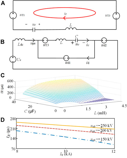
FIGURE 4. (A) Equivalent circuit of the capacitor discharging during t3 and t4. (B) equivalent discharge circuit of the capacitor during t4 and t5; (C) relations of tR, L, and C (D) relations of IR. Io. and uc0.
After a metallic fault occurs at the load side of the C-DCCB, the system side of the C-DCCB is equivalent to a voltage source connected in series with an inductor Ldc. The equivalent capacitor discharge circuit during t4 and t5 is shown in Figure 4B, where isys is the system current, id is the current flowing through D1, udi is the voltage drop in Di, i = 1, 2. Assume that the diodes have the same voltage drop of ud, then we can obtain:
In Eq. 3, the initial values of uc and ic can be obtained from those final values in Eq. 2; isys and ic have the same initial value, and id has an initial value of 0.
In this analysis, Us = 200 kV, Ldc = 0.04 H, uc0 = −200 kV, and the fault current at t3 has a value of I0 = 10 kA. Substituting these parameters into (2) and (3), the relations of the reverse-bias time tR, L and C can be obtained. As shown in Figure 4C, tR increases with C, because the larger capacitor stores more energy to maintain the reverse-bias of T1. When L is small, tR increases with L. However, when L exceeds a critical value LC, tR decreases with L. When C is too small and L is too large, tR is 0. When C = 9 μF and L = 1.2 mH, the relations of tR, I0 and uc0 are shown in Figure 4D. The value of tR decreases with I0 and increases with the absolute value of uc0.
According to the relations of tR and system parameters, the parameter design principles of the C-DCCB are as follows: 1) the values of L and C should guarantee that tR is greater than the turn-off time tq under the worst interruption condition, i.e., the C-DCCB interrupts the maximum fault current when the initial capacitor voltage uc0 has a minimum absolute value; 2) the value of L should be close to the critical value Lc to improve the utilization efficiency of L and C.
3.2 Fault property identification
3.2.1 Analysis model:
This section takes the reclosing after a positive pole fault as an example. As shown in Figure 5A, the systems on both sides of the negative pole are represented by the Thevenin equivalent circuits; Ueq1 and Ueq2 are Thevenin voltages; Zeq1 and Zeq2 are Thevenin impedances; ur is the capacitor voltage at the beginning of reclosing. Taking the fault point as a boundary, the DC line is divided into two parts. If the fault is permanent, the switch k1 is closed; otherwise, k1 is opened. The turn-on commands of thyristors TL and TR represent the reclosing commands of C-DCCBs on the left and right sides, respectively.
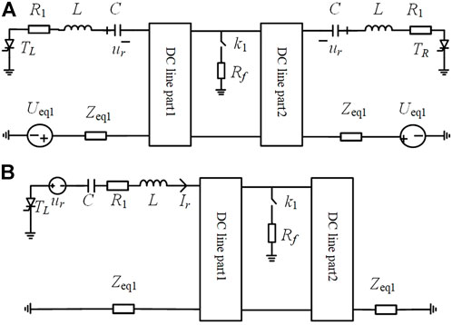
FIGURE 5. (A)Schematic of the system circuit after isolating the fault pole; (B)equivalent system circuit during the reclosing.
We assume that the C-DCCB on the left side closes S2, T2 and T5, which is equivalent to that TL is turned on in Figure 5A. According to the superposition theorem, during the reclosing, the system response change is caused by the excitation of the voltage source ur. Considering only the excitation of ur, the equivalent system circuit is shown in Figure 5B.
Using the DC line’s frequency-dependent parameter, the nodal admittance matrix of the DC line can be obtained, and then the bus admittance matrix of the circuit in Figure 5B can be established. The self-impedance of the node connecting the voltage source ur and the capacitor C is marked as Zself, then the current injected into the DC line, marked as Ir, is:
where s is the Laplace operator.
During reclosing, the capacitor voltage uc is:
The value of uc in the frequency domain can be calculated by combining (4) and (5). The value of uc in the time domain can be obtained using the numerical inversion of the Laplace transform (Gómez and Uribe, 2009). The detailed calculation process can refer to the method in (Guo et al., 2021) and is not repeated in this paper.
3.2.2 Transient fault:
At the beginning of reclosing, the voltage source ur generates a current traveling wave on the DC line. When the fault is transient, because the DC line end is an open circuit, the current traveling wave is totally reflected at the DC line end, and the reflection wave is in the opposite direction of the original traveling wave. When the reflection current wave transmits to the DC line head, Ir decreases to 0, and the thyristor TL is reversely biased, causing the capacitor voltage uc keeps unchanged.
According to the system parameters in Section 4, we take ur = 1 pu, C = 9 μF, L = 1.2 mH, R1 = 150 Ω, Zeq1 = Zeq2 = 100 Ω. As shown in Figure 6A, the capacitor discharges through the DC line during reclosing without fault, and uc gradually decreases. Because of the current reflection wave, the thyristor TL is turned off and uc keeps unchanged after 1.36 ms. The deviation between the calculation and simulation values of uc is relatively small, which validates the accuracy of the analysis model.
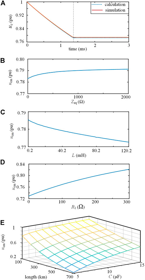
FIGURE 6. (A) Simulation and calculation values of Δu during reclosing without fault; (B) relation between ucm and Zeq (C) relation between ucm and L (D) relation between ucm and R1 (E) relations of ucm, C and line length.
During reclosing, the minimum value of uc is marked as ucm. The relations of ucm and the system parameters are discussed using the above analysis model. The values of Zeq1 and Zeq2 are related to the non-fault area of the DC grid. When Zeq1 = Zeq2 = Zeq, the relation between ucm and Zeq is shown in Figure 6B. When Zeq increases from 0 to 2 kΩ, ucm only increases by 1.0%, indicating that the non-fault area of the DC grid has little influence on ucm.
As shown in Figure 6C, when L increases from 0.2 to 120.2 mH, ucm only decreases by 1.6%, indicating that the influence of L on ucm is not significant. As shown in Figure 6D, ucm increases with increasing R1, because R1 limits the amplitude of the current traveling wave, thus limiting the discharge of capacitor C. As shown in Figure 6E, ucm increases with the increasing C. With the DC line length increase, the arrival time of the current reflection wave increases, causing the increase in capacitor discharge time and the decrease of ucm.
3.2.3 Permanent fault:
After reclosing the C-DCCB with a permanent fault, the current traveling wave will be reflected at the fault point. If the fault resistance is less than the line wave impedance, the current reflection wave has the same polarity as the original current traveling wave; otherwise, compared to the original current traveling wave, the current reflection wave has an opposite polarity and smaller amplitude. Therefore, the traveling wave effect will not cause the capacitor current to cross zero during reclosing with a permanent fault.
As shown in Figure 3G, the capacitor significantly discharges through R1, L and the fault line during reclosing with a permanent fault. The equivalent parallel admittance of the DC line has little effect on the discharge. Using the lumped parameter model of the DC line, the equivalent capacitor discharge circuit is shown in Figure 7A, where Req and Leq are the equivalent resistance and inductance of the DC line, respectively. For this second-order circuit, when
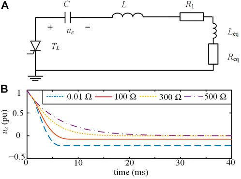
FIGURE 7. (A) Equivalent discharge circuit during reclosing with a permanent fault; (B) waveforms of uc, when the permanent fault has different fault resistances.
As shown in Figure 7B, for a permanent fault located at the DC line end, when the fault resistance is 0 and 100 Ω, the discharge is underdamped, and the minimum value of uc is less than 0. When the fault resistance is 300 and 500 Ω, the discharge process is overdamped, and uc decreases to 0. These results are consistent with the above analysis.
3.2.4 Criteria for identifying the fault property:
According to the above analysis, during reclosing with transient faults, uc decreases to a positive value ucm, which can be calculated using Eq. 4 and Eq. 5. During reclosing with permanent faults, uc decreases to be no more than 0. A permanent fault is identified using the following criterion:
where uth is the voltage threshold, and umar1 is a positive safety margin.
A transient fault is identified using the following criterion:
A slighter fault causes a slower capacitor discharge rate during reclosing with a permanent fault. The values of uerror and ∆t should satisfy the following conditions: 1) the criterion in Eq. 7 is not true in the case of the slightest permanent fault, which occurs at the end of DC line and has the largest fault resistance; and 2) uerror is greater than the maximum measurement error.
In addition, to correctly identify the transient fault that lasts longer than hundreds of milliseconds, the following method is adopted: after identifying a permanent fault, the C-DCCB will perform another reclosing attempt to identify the fault property again unless the number of reclosing attempts reaches the maximum value allowed by the system.
4 Simulation results
4.1 Simulation parameters
As shown in Figure 8A, a four-terminal bipolar DC grid is established in PSCAD/EMTDC, and the rated voltage is ±200 kV. In the DC grid, each station contains 2 MMCs, and its neutral point is directly earthed. For the equivalent model, all sub-modules in each MMC arm are equivalent to a Thevenin equivalent circuit; thus, the simulation efficiency is greatly improved. The DC grid is bipolar and has a rated voltage of ±200 kV, and the detailed equivalent model of MMC in (Cigré, 2014) is used. Both ends of the DC line are equipped with C-DCCBs and current-limiting inductors of 0.04 H. The C-DCCB located on the Bus1 side of Line 4 is marked as B1 and taken as an example. For simplicity, only simulation results of the positive pole are shown in this paper. The parameters of the C-DCCB and simulation model are shown in Table 1 and Table 2, and the design of reclosing parameters is presented as follows.
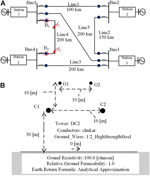
FIGURE 8. (A) Topology of the DC grid; (B) configuration of transmission line.
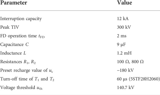
TABLE 1. Parameters of the C-DCCB.
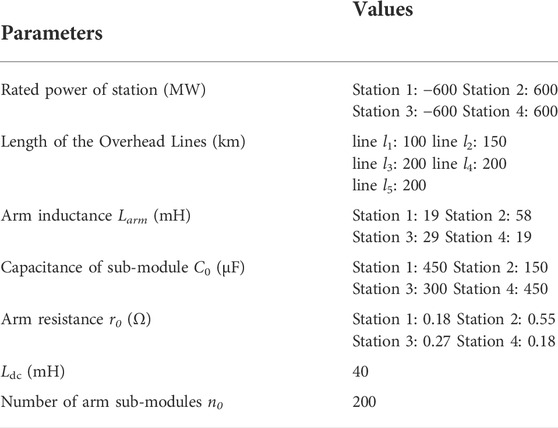
TABLE 2. Main parameters of the HVDC Grid.
During the interruption, the internal capacitor voltage uc is charged to the peak TIV of 300 kV. After the interruption, the capacitor C slowly discharges through the arrester and D3. After a time delay of 300 ms, the capacitor voltage is discharged to ur = 192 kV at the beginning of reclosing. The transmission line is based on the frequency-dependent model, and the line configuration is shown in Figure 8B. Substituting the C-DCCB and line parameters into (4) and (5), we can obtain that ucm = 0.785 ur. In this paper, the safety margin umar1 is taken as 10 kV. Then, the voltage threshold uth in (6) and (7) has a value of 0.785 × 192–10 = 140.7 kV.
For DC grid protections, the maximum value of fault resistance is usually hundreds of ohm. In simulations, even if the permanent fault located on the B2 side of Line 4 has a fault resistance of up to 1 kΩ, uc decreases to uth within 3 ms during the reclosing process. Thus, as long as ∆t is greater than 3 ms and uerror is less than (ur−uth), the permanent fault will not cause malfunctions of criterion in Eq. 7. We assume that the capacitor voltmeter has a voltage range of 350 kV and an accuracy ratio of 0.1%; thus, the maximum measurement error of the voltmeter is 0.35 kV. Considering these above conditions, we select uerror and ∆t as 0.5 kV and 5 ms, respectively.
4.2 Interruption of fault current
As shown in Figure 8A, considering the most serious fault condition, a metallic fault occurs at the line side of B1 at t = 0 ms, and the initial capacitor voltage is −180 kV. After the fault is detected at t = 1 ms, the interruption results are shown in Figure 9, where idc, iT1, ic and iar are the currents flowing through Line 4, T1, C and arrester, respectively.
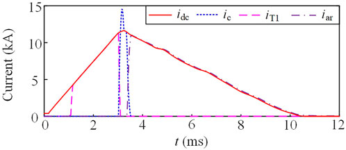
FIGURE 9. Current waveforms during the interruption.
We assume that the protection detects the fault at t = 1 ms. As shown in Figure 9, after t = 1 ms, T1 is turned on and then the LCS is turned off. At t = 1.16 ms, idc is commutated into the MB, and the FD is opened without arc. Substituting system parameters into (1), T3 is turned on at t = 3.1 ms. After that, ic rapidly exceeds the fault current; thus, T1 is reversely biased. The reverse-bias of T1 continues until idc exceeds ic. The reverse-bias time is 120 μs and two times tq, which is sufficient to turn off T1. With the charging of the capacitor, idc reaches the maximum value of 11.7 kA at t = 3.29 ms and then gradually decreases. At t = 3.42 ms, idc is commutated into the arrester. At t = 10.3 ms, idc falls to below 10 A.
For the typical hybrid DCCB in (Hafner and Jacobson, 2011), the fault current decreases almost immediately after the FD recovers the dielectric strength. For the C-DCCB, the fault current begins to fall at t = 3.29 ms, which is only 0.13 ms later than the instant that the FD recovers the dielectric strength at t = 3.16 ms. The time interval from the fault inception to the moment that the fault current begins to decrease is defined as the fault neutralization time. The fault neutralization time of C-DCCB is only a few hundred microseconds longer than that of typical hybrid DCCB, indicating a quick interruption speed.
4.3 Reclosing with a permanent fault
4.3.1 Permanent metallic fault
We set a permanent fault at the midpoint of Line 4 at t = 0 ms, and the fault resistance is 0.01 Ω. At t = 300 ms, B1 begins to reclose, i.e., T2 and T5 are turned on. As shown in Figure 10A, uc gradually decreases during reclosing and is smaller than uth = 140.7 kV after t = 301.08 ms. Thus, B1 identifies the permanent fault. During reclosing, the capacitor discharges through R1, L and the fault line, and this second-order discharge circuit is underdamped because the fault resistance is small. As shown in Figure 10A, when ic crosses 0 at t = 305.08 ms, uc decreases to a negative value, and T2 and T5 are turned off. After that, S2 is opened to isolate the permanent fault.
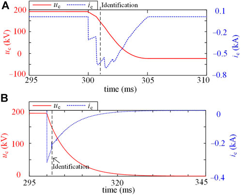
FIGURE 10. Simulation results during reclosing: (A) permanent metallic fault: (B) permanent high resistance fault.
At the initial stage of reclosing, ic undergoes multiple abrupt changes because of the traveling wave effect. The traveling impact decreases over time and is not significant after 302.5 ms. At t = 305.08 ms, the zero crossing of ic is caused by the underdamped discharge process rather than the traveling effect, which is consistent with the analysis in Section 3.2.
4.3.2 Permanent high-resistance fault
We set a permanent fault at the B2 side of Line 4, and the fault resistance is 500 Ω. After the interruption, B1 begins to reclose at t = 300 ms. As shown in Figure 10B, uc decreases to uth = 140.7 kV at t = 301.76 ms; thus, the permanent fault is identified. Because the fault resistance is large, the capacitor discharge process is overdamped. At t = 320 ms, uc decreases to 6.7 kV and ic is smaller than 10 A. Then, S2 begins to be opened, and the fault is totally isolated at t = 340 ms.
4.4 Reclosing with a transient fault
After isolating a transient fault on Line 4, B1 begins to reclose at t = 300 ms; thus, a current traveling wave is injected into Line 4. The current traveling wave transmits along Line 4 and is totally reflected at the end of Line 4. As shown in Figure 11A, at t = 301.40 ms, the current reflection wave arrives at the head of Line 4 and causes ic to cross 0, because the reflected wave is in the opposite polarity of the original traveling wave. After that, uc maintains at 151 kV. At t = 306.36 ms, the criterion in Eq. 7 is activated, indicating that the fault on Line 4 has disappeared. After that, B1 turns on T1 and T5; thus, the DC grid charges the capacitor C and Line 4 through the resistor R2. Finally, the capacitor C is charged to the system voltage.
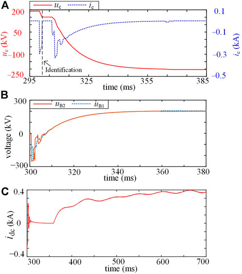
FIGURE 11. Simulation results during reclosing with a transient fault: (A) the value of uc and ic; (B) line voltages uB1 and uB2; (C) line current idc.
As shown in Figure 11B, the voltage of Line 4 on B1 side, marked as uB1, increases to 190 kV at t = 339.20 ms, and B1 begins to close S1. At t = 339.24 ms, the voltage of Line 4 on B2 side, marked as uB2, increases to 190 kV; thus, B2 directly identifies that the line fault has disappeared, and S1, S2, FD and LCS in B2 are successively closed. After that, uB1 and uB2 gradually recover to close to 200 kV.
During the reclosing process, the discharging of the capacitor and charging of Line 4 cause negative and positive abrupt changes in idc, respectively, as shown in Figure 11C. After t = 360 ms, MCs of B1 and B2 have been closed; thus, idc begins to restore to the normal value. Line 4 begins to restore the power transmission. This restoration process takes hundreds of milliseconds. A special control strategy can be used to improve the restoration speed, which will be considered in future work.
4.5 Comparisons
In this section, the C-DCCBs in (Liu, 2019), (Wu et al., 2019) and (Guo et al., 2020) are compared with the proposed C-DCCB.
4.5.1 Interruption performance
In these C-DCCBs, only the C-DCCB in (Liu, 2019) opens the FD with arcing, which increases the FD operation time. Thus, when the same FD is used, the C-DCCB in (Liu, 2019) has a longer interruption time than the other three C-DCCBs. For the other three C-DCCBs, the fault current decreases within a few hundred microseconds after the FD recovers the dielectric strength, indicating a quick interruption speed.
Except for the MC, the C-DCCB in (Liu, 2019) cannot provide another current path to conduct the load current, whereas the other three C-DCCBs can conduct the load current using the thyristors in the MB. Therefore, the C-DCCB in (Liu, 2019) does not have the pre-activation ability, whereas the other three C-DCCBs have the pre-activation ability. Combining the protection and pre-activation, these three C-DCCBs can further reduce the interruption time.
During the interruption of backward direction currents, the C-DCCB in (Liu, 2019) cannot decrease the FD current to 0 until the capacitor discharge current is reversed, causing a larger interruption time. In (Wu et al., 2019), the C-DCCB interrupts only the forward direction currents and cannot interrupt the backward direction fault currents. Because of the symmetry of topology, the proposed C-DCCB can interrupt bidirectional currents with the same performance, and the C-DCCB in (Guo et al., 2020) also has this interruption characteristic.
4.5.2 Semiconductor cost
The peak TIV of these C-DCCBs, marked as Up, is selected as 300 kV to compare the semiconductor cost. For the proposed C-DCCB, T1 and T2 are turned off during the interruption of the forward direction and backward direction currents, respectively. They should be composed of fast thyristor modules to maintain a short interruption time. The thyristors T3 and T4 are naturally turned off after the interruption, and the thyristor T5 is naturally turned off after the precharge process; thus, thyristors T3, T4 and T5 can be composed of phase-control thyristor modules. Then, the proposed C-DCCB contains phase-control thyristor modules with a voltage rating of 3Up, fast thyristor modules with a voltage rating of 2Up, and diode modules of 3Up.
For the C-DCCB in (Liu, 2019), a triggered spark gap or reverse-conducting thyristor can be used to trigger the capacitor discharge during the interruption. The reverse-conducting thyristor comprises phase-control thyristor modules with a voltage rating of Up and diode modules with a voltage rating of Up. In (Wu et al., 2019), three thyristors need to be turned off during the interruption process. They should be composed of fast thyristor modules with a voltage rating of 3Up; one thyristor is naturally turned off after the interruption and can be composed of phase-control thyristor modules with a voltage rating of Up. In (Guo et al., 2020), one thyristor is turned off during the interruption process and composed of fast thyristor modules with a voltage rating of Up. In addition, phase-control thyristor modules with a voltage rating of 5Up and diode modules with a voltage rating of 5Up are also needed in (Guo et al., 2020).
We assume that the thyristor module N2825TE400 (4 kV, ¥ 3,723 (findic and digikey, 2021)), fast thyristor module 5STF 28H2060 (2 kV, ¥ 2,755 (findic and digikey, 2021)) and diode module W3082MC450 (4.5 kV, ¥ 1,610 (findic and digikey, 2021)) are used, and a safety voltage margin of 2 is maintained. Then, the device costs of these C-DCCBs are given in Table 3, and the unit of device costs is RMB. The C-DCCBs in (Liu, 2019) and (Guo et al., 2020) have the smallest and largest semiconductor costs, respectively, and the proposed C-DCCB has a higher semiconductor cost than the C-DCCB in (Wu et al., 2019).
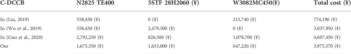
TABLE 3. Semiconductor costs of C-DCCBs.
According to the evaluation method in (Evans et al., 2019), the capacitor C of 9 μF in the proposed C-DCCB has a cost of ¥ 2,231,323, which is more than half of the total semiconductor cost of ¥ 3,975,570. Thus, the capacitor cost is vital for evaluating the construction cost of C-DCCBs. For C-DCCBs, the capacitor value is related to the interruption conditions, such as voltage rating and interruption capacity. Comparing capacitor costs of C-DCCBs should be based on the same interruption conditions. Considering that the capacitor values in (Liu, 2019), (Wu et al., 2019), (Guo et al., 2020) and this paper are selected based on different interruption conditions, the capacitor costs are not compared to avoid injustice.
4.5.3 Reclosing performance
For the C-DCCB in (Liu, 2019), the polarities of the capacitor voltage are in the opposite directions before and after the interruption. The C-DCCB in (Liu, 2019) requires additional circuits to restore the normal state of the capacitor before reclosing, which increases the construction cost and is not conducive to fast reclosing. The C-DCCB in (Wu et al., 2019) has the same polarity of capacitor voltage before and after the interruption, and the C-DCCB in (Guo et al., 2020) can quickly restore the initial capacitor voltage using the grounded branch. Thus, these two C-DCCBs have a fast reclosing ability.
However, direct reclosing rather than adaptive reclosing is considered in previous papers. The direct reclosing strategy directly recloses the C-DCCB to reconnect the HVDC grid to the isolated line, and the C-DCCB interrupts the fault current in case of permanent faults. Considering that these C-DCCBs have similar performances during the direct reclosing, the proposed C-DCCB is used to perform the direct reclosing to validate the advantage of the proposed adaptive reclosing strategy.
For the first direct reclosing method, which is marked as DR1, the proposed C-DCCB successively closes S1, S2 and FD. For the second direct reclosing method, which uses the pre-activation ability and is marked as DR2, the proposed C-DCCB successively closes S1—S2 and turns on T1—T2, and then the system current is commutated into the MC by closing FD and turning on LCS. Compared with the DR1, the DR2 effectively reduces the interruption time during the permanent fault because the process of commutating the fault current from MC into MB is avoided. The proposed adaptive reclosing strategy is marked as AR.
We set a permanent metallic fault at the head of Line 4. For DR1 and DR2, we assume that the fault detection time is only 0.2 ms. As shown in Figure 12, compared with DR1, DR2 reduces the maximum value of idc from 9.73 to 2.11 kA because DR2 has a much shorter interruption time. For the proposed adaptive reclosing strategy, the maximum absolute value of idc is only 1.22 kA. Therefore, compared with direct reclosing strategies, the proposed adaptive reclosing strategy effectively limits the fault current during the permanent fault.
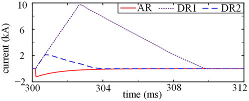
FIGURE 12. Waveforms of idc when the C-DCCB recloses with a permanent fault using different reclosing strategies.
We set a transient fault at Line 4, and B1 recloses using different reclosing strategies. The simulation results are shown in Figure 13. For DR1 and DR2, the HVDC grid directly charges the positive pole of Line 4, causing oscillations in the Bus1 voltage ubus1, and DR1 and DR2 almost have the same waveforms of ubus1. For the adaptive reclosing strategy, the HVDC grid charges the positive pole of Line 4 and the internal capacitor of C-DCCB through the resistor R2 at 301.6 ms; thus, ubus1 drops to 168 kV and then quickly returns to the normal value without significant oscillations. Compared with direct reclosing strategies, the adaptive reclosing strategy effectively reduces the voltage oscillations in HVDC grids.
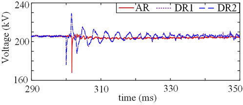
FIGURE 13. Waveforms of ubus1 when the C-DCCB recloses with a transient fault using different reclosing strategies.
5 Conclusion
This paper proposes a novel C-DCCB with adaptive reclosing ability. The parameter design is analyzed to ensure the reliable turn-off of the thyristor, which is key to the successful interruption. The transient process during adaptive reclosing is analyzed to identify the fault property. The semiconductor cost, interruption and reclosing performances of the proposed C-DCCB are compared with those of previous C-DCCBs. The main conclusions are summarized as follows.
1) The proposed C-DCCB achieves good interruption performances, such as quick interruption speed and pre-activation ability. During interruptions, the fault current decreases within a few hundred microseconds after the FD restores the dielectric strength. Using the pre-activation, the fault current is commutated into the MB during the protection time, thus effectively reducing the interruption time.
2) During the adaptive reclosing, the internal capacitor has a large initial voltage and discharges through the grounded branch. The capacitor voltage decreases to a positive value when the fault is transient, and the capacitor voltage is no more than 0 when the fault is permanent; thus, the fault property is identified using the capacitor voltage.
3) The adaptive reclosing of C-DCCBs is less considered in previous papers. An adaptive reclosing strategy is designed for the proposed C-DCCB, which is the main contribution of this paper. Using the adaptive reclosing strategy, the proposed C-DCCB avoids the second fault shock in case of permanent faults, and the power transmission is restored without significant voltage oscillations in transient faults.
Data availability statement
The original contributions presented in the study are included in the article/Supplementary Material, further inquiries can be directed to the corresponding author.
Author contributions
ZX: Writing-Original Draft, Visualization. JL: Writing–Review and Editing, Supervision. YG: Conceptualization, Methodology, Writing-Original Draft. YW: Supervision.
Funding
This work is supported by the National Natural Science Foundation of China (52107130).
Acknowledgments
This is a brief acknowledgement of the contributions of individual colleagues, institutions, or agencies that assisted the writers’ efforts in the writing of this article.
Conflict of interest
The authors declare that the research was conducted in the absence of any commercial or financial relationships that could be construed as a potential conflict of interest.
Publisher’s note
All claims expressed in this article are solely those of the authors and do not necessarily represent those of their affiliated organizations, or those of the publisher, the editors and the reviewers. Any product that may be evaluated in this article, or claim that may be made by its manufacturer, is not guaranteed or endorsed by the publisher.
References
An, T., Tang, G., and Wang, W. (2017). Research and application on multi-terminal and DC grids based on VSC-HVDC technology in China. High. Volt. 2, 1–10. doi:10.1049/hve.2017.0010
Augustin, T., Becerra, M., and Nee, H.-P. (2021). Enhanced active resonant DC circuit breakers based on discharge closing switches. IEEE Trans. Power Deliv. 36 (3), 1735–1743. doi:10.1109/tpwrd.2020.3014084
Bucher, M. K., and Franck, C. M. (2016). fault current interruption in multiterminal HVDC networks. IEEE Trans. Power Deliv. 31 (1), 87–95. doi:10.1109/tpwrd.2015.2448761
Chen, M., Xu, H., and Zhang, Z. (2018). Design and simulation of coupling mechanical high voltage DC circuit breaker. High. Volt. Eng. 44 (2), 380–387.
Chen, W., Zeng, R., He, J., Wu, Y., Wei, X., Fang, T., et al. (2021). Development and prospect of direct-current circuit breaker in China. High. Volt. 6, 1–15. doi:10.1049/hve2.12077
Cigré (2014). TB604—guide for the development of models for HVDC converters in a HVDC grid joint working group B4.57.
Evans, N., Dworakowski, P., Al-Kharaz, M., Hegde, S., Perez, E., and Morel, F. (2019). “Cost-performance framework for the assessment of Modular Multilevel Converter in HVDC transmission applications,” in IECON 2019- 45th annual conference of the (Lisbon, Portugal: IEEE Industrial Electronics Society), 4793–4798.
findic and digikey (2021). findic digikey. Available: https://www.findic.com/https://www.digikey.com/(accessed on Aug. 19, 2021).
Gómez, P., and Uribe, F. A. (2009). The numerical Laplace transform: An accurate technique for analyzing electromagnetic transients on power system devices. Int. J. Electr. Power & Energy Syst. 31 (2–3), 116–123. doi:10.1016/j.ijepes.2008.10.006
Guo, Y., Li, H., Liang, Y., and Wang, G. (2021). A method to calculate short-circuit faults in high-voltage DC grids. IEEE Trans. Power Deliv. 36 (1), 267–279. doi:10.1109/tpwrd.2020.2978625
Guo, Y., Wang, G., Zeng, D., Li, H., and Chao, H. (2020). A thyristor full-bridge-based DC circuit breaker. IEEE Trans. Power Electron. 35 (1), 1111–1123. doi:10.1109/tpel.2019.2915808
Hafner, J., and Jacobson, B. (2011). “Proactive hybrid HVDC breakers—a key innovation for reliable HVDC grids,” in CIGRE bologna conf, 1–8.
Hassanpoor, A., Hafner, J., and Jacobson, B. (2015). Technical assessment of load commutation switch in hybrid HVDC breaker. IEEE Trans. Power Electron. 30 (10), 5393–5400. doi:10.1109/tpel.2014.2372815
Hertem, V., and Ghandhari, M. (2010). “Multi-terminal VSC HVDC for the European supergrid: Obstacles. Renew. Sustain. Energy Rev. 14, 3156–3163.
Jamshidifar, A., and Jovcic, D. (2018). Design, modeling and control of hybrid DC circuit breaker based on fast thyristors. IEEE Trans. Power Deliv. 33 (2), 919–927. doi:10.1109/tpwrd.2017.2761022
Jovcic, D., Tang, G., and Pang, H. (2019). Adopting circuit breakers for high-voltage dc networks: Appropriating the vast advantages of dc transmission grids. IEEE Power Energy Mag. 17 (3), 82–93. doi:10.1109/mpe.2019.2897408
Li, B., He, J., Li, Y., and Wen, W. (2020). A novel DCCB reclosing strategy for the flexible HVDC grid. IEEE Trans. Power Deliv. 35 (1), 244–257. doi:10.1109/tpwrd.2019.2938594
Liu, C., (2019). “535kV high voltage DC circuit breaker insulation test analysis,” in 2019 5th international conference on electric power equipment - switching technology (Kitakyushu, Japan: ICEPE-ST), 580–584.
Mei, J., Ge, R., Zhu, P., Fan, G., Wang, B., and Yan, L. (2021). An adaptive reclosing scheme for MMC-HVDC systems based on pulse injection from parallel energy absorption module. IEEE Trans. Power Deliv. 36 (3) 1809–1818. doi:10.1109/tpwrd.2020.3015311
Pei, X., Tang, G., and Zhang, S. (2019). Sequential auto-reclosing strategy for hybrid HVDC breakers in VSC-based DC grids. J. Mod. Power Syst. Clean. Energy 7 (3), 633–643. doi:10.1007/s40565-018-0486-1
Shi, Z., Zhang, Y., Jia, S., Song, X., Wang, L., and Chen, M. (2015). Design and numerical investigation of a HVDC vacuum switch based on artificial current zero. IEEE Trans. Dielectr. Electr. Insul. 22 (1), 135–141. doi:10.1109/tdei.2014.004533
Sima, W., Fu, Z., Yang, M., Yuan, T., Sun, P., Han, X., et al. (2019). A novel active mechanical HVDC breaker with consecutive interruption capability for fault clearances in MMC-HVDC systems. IEEE Trans. Ind. Electron. 66 (9), 6979–6989. doi:10.1109/tie.2018.2878115
Song, G., Wang, T., and Hussain, K. S. T. (2019). DC line fault identification based on pulse injection from hybrid HVDC breaker. IEEE Trans. Power Deliv. 34 (1), 271–280. doi:10.1109/tpwrd.2018.2865226
Technical Information (2012). Bipolar semiconductors. Infineon. Available: https://www.infineon.com/cms/de/product/power/high-power-diodes-thyristors/thyristor-diode-discs/?redirId=28573#! documents.
Torwelle, P., Bertinato, A., Grieshaber, W., Yang, Y., Raison, B., Le, T. D., et al. (2021). Pre-energization concept for overhead lines in MTDC grids using DCCB internal capacitor. IEEE Trans. Power Deliv. 37 (1–1), 155–164. doi:10.1109/tpwrd.2021.3054599
Wang, T., Song, G., and Hussain, K. S. T. (22032019). Adaptive single-Pole auto-reclosing scheme for hybrid MMC-HVDC systems. IEEE Trans. Power Deliv. 34 (6), 2194–2203. doi:10.1109/tpwrd.2019.2921674
Wen, W., Huang, Y., Sun, Y., Wu, J., Al-Dweikat, M., and Liu, W. (2016). Research on current commutation measures for hybrid DC circuit breakers. IEEE Trans. Power Deliv. 31 (4), 1456–1463. doi:10.1109/tpwrd.2016.2535397
Wen, W., Liu, H., Li, B., Li, P., Zhang, N., Gao, C., et al. (41332021). Novel reclosing strategy based on transient operating voltage in pseudobipolar DC system with mechanical DCCB. IEEE Trans. Power Electron. 36 (4), 4125–4133. doi:10.1109/tpel.2020.3022070
Wen, W., Wang, Y., Li, B., Huang, Y., Li, R., and Wang, Q. (94312018). Transient current interruption characteristics of a novel mechanical DC circuit breaker. IEEE Trans. Power Electron. 33 (11), 1. doi:10.1109/tpel.2018.2797243
Wu, Y., Wu, Y., Rong, M., and Yang, F. (2019). Development of a novel HVdc circuit breaker combining liquid metal load commutation switch and two-stage commutation circuit. IEEE Trans. Ind. Electron. 66 (8), 6055–6064. doi:10.1109/tie.2018.2870387
Wu, Y., Wu, Y., Yang, F., Rong, M., and Hu, Y. (2020). A novel current injection DC circuit breaker integrating current commutation and energy dissipation. IEEE J. Emerg. Sel. Top. Power Electron. 8 (3), 2861–2869. doi:10.1109/jestpe.2019.2911103
Wu, Y., Wu, Y., Yang, F., Rong, M., and Hu, Y. (2020). Bidirectional current injection MVDC circuit breaker: Principle and analysis. IEEE J. Emerg. Sel. Top. Power Electron. 8 (2), 1536–1546. doi:10.1109/jestpe.2018.2888590
Yang, S., Xiang, W., Lu, X., Zuo, W., and Wen, J. (11232020). An adaptive reclosing strategy for MMC-HVDC systems with hybrid DC circuit breakers. IEEE Trans. Power Deliv. 35 (3), 1111–1123. doi:10.1109/tpwrd.2019.2935311
Keywords: adaptive reclosing, dc circuit breaker, fault property identification, HVDC grid, thevenin equivalent circuits
Citation: Xu Z, Liang J, Guo Y and Wang Y (2022) A capacitor-based DC circuit breaker for HVDC power grid. Front. Energy Res. 10:1013696. doi: 10.3389/fenrg.2022.1013696
Received: 07 August 2022; Accepted: 25 August 2022;
Published: 13 September 2022.
Edited by:
Chaolong Zhang, Anqing Normal University, ChinaReviewed by:
Shuo Zhang, Shandong University, ChinaRui Li, University of Strathclyde, United Kingdom
Bhaskar Mitra, Pacific Northwest National Laboratory (DOE), United States
Xiuyan Wei, Shandong University, China
Copyright © 2022 Xu, Liang, Guo and Wang. This is an open-access article distributed under the terms of the Creative Commons Attribution License (CC BY). The use, distribution or reproduction in other forums is permitted, provided the original author(s) and the copyright owner(s) are credited and that the original publication in this journal is cited, in accordance with accepted academic practice. No use, distribution or reproduction is permitted which does not comply with these terms.
*Correspondence: Yanxun Guo, Z3VveWFueHVuQHp6dS5lZHUuY24=