 Yuanshi Zhang
 Liwei Wang
 Chris Struthers
 Qinran Hu
- 1School of Electrical Engineering, Southeast University, Nanjing, China
- 2School of Engineering, University of British Columbia, Kelowna, BC, Canada
- 3StruthersTech, Penticton, BC, Canada
This paper explores new design methods for correcting unbalanced power distribution networks in order to improve the power quality and reliability for sensitive industrial loads. While traditional compensators typically need to be connected to all the three phases of the AC network, this paper proposes a novel three-phase voltage balancing compensator that can operate with a connection to only two of the three phases. The new concept is based on the phasor symmetrical component theory, which can be implemented using either mechanically switched reactors (MSRs), TCRs (thyristor-controlled reactors) or VSCs (Voltage source converters). Three methods are presented to calculate the value of the proposed two-phase compensator, i.e., discrete solution, analytical solution and novel simplified solution. The discrete solution is solved via the exhaustive search method, which was successfully used by StruthersTech to correct the power quality of an unbalanced industrial power system. The analytical solution is based on the nodal voltage of analysis method. The simplified solution derives a practical albeit approximated relationship between the negative sequence source voltage and zero sequence load voltage, thus avoiding the need to solve nonlinear equations. Dynamic simulations are implemented using MATLAB/Simulink Simscape Blockset to validate the effectiveness of the proposed two-phase voltage balancing method.
1 Introduction
With the large-scale intermittent renewable energy integrating into the smart grids, electrical engineers and researchers have heighten their level of concentration to power quality problem (Chen et al., 2020; Xiao et al., 2021; Hu et al., 2022a; Hu et al., 2022b). Power quality can be defined as the supply of adequately high-grade electrical utility services to the consumer/customer. To guarantee the power quality is one of the fundamental tasks at both transmission and distribution levels. Power quality problems, especially voltage unbalance, have attracted wide attention, and a lot of research has been carried out on this topic (Fuchs and Masoum, 2008).
The adverse effects of the voltage unbalance are normally less serious than the current unbalance. Nevertheless, the loads and power electronics equipment may suffer more from the voltage unbalance (Xu et al., 2010). The negative impact of voltage unbalance on power grid and equipment such as induction motors and power electronic converters and drives has been studied in depth (Wang, 2001; Lee et al., 2006; Wei et al., 2022). Further, the available capacity of transformers and generators is negatively impacted by voltage unbalance, increasing the burden on the utility. Therefore, voltage compensation of non-linear and/or poor power factor loads and load balancing is an important issue in the modern power distribution system (Kazmierkowski, 2007). Normally, single-phase loads in a distribution system that are not consistently balanced between all three phases will result in unbalanced voltage at the load point of utilization (Woll, 1975). This is particularly true in terms of rural electric power grids with long distribution cables and/or fed by induction machines actuated by wind turbine generators. Moreover, large urban power grids also suffer from unbalanced voltage issues (Muljadi et al., 1999), (Muljadi, 1984).
Amongst the previous works related to the correction of the power quality, unbalanced voltage compensation has already been well studied. In (Peng and Lai, 1996; Akagi et al., 1999; Mishra et al., 2001), different compensation methods adopting instantaneous reactive power theory for shunt power filters are proposed. The loads in an unbalanced three-phase four-wire system are compensated with a static VAR compensator (SVC) (IEEE Special Stability Controls Working Group, 1994; Flores et al., 2009; Sun et al., 2011; Mi et al., 2018) combined with a series active filter in (Lee and Wu, 2000). In (Alkayyali and Ghaeb, 2019), a hybrid Particle Swarm Optimization–Artificial Neural Network algorithm is proposed to deal with the voltage unbalance issue by regulating the firing angles of thyristor controlled reactors (TCRs). The unbalanced voltage problem in distribution system is overcome by the dynamic voltage restorer (DVR), which is a power-electronic device that can protect sensitive loads from unprepared contingencies (Ghosh and Ledwich, 2002; Omar and Rahim, 2012; Sadigh and Smedley, 2012). Static VAR compensators (STATCOMS) are widely used for unbalanced voltage/current compensation in (Xu et al., 2010), (Escobar et al., 2001; Struthers, 2001; Mishra et al., 2007). In (Xu et al., 2010), an instantaneous power theory is used with three control schemes for voltage and current compensation. Two kinds of compensation strategies are proposed for unbalanced and distorted voltages in (Mishra et al., 2007). However, all of the existing literatures need to use three-phase compensators for voltage compensation. In this work, a novel two-phase voltage balancing compensator is proposed based on the phasor symmetrical component theory, which can be realized by mechanically switched reactors (MSRs), TCRs, or Voltage source converters (VSCs). The two-phase compensator has the potential to significantly reduce the capital investment cost.
This work focuses on developing the algorithm of a novel two-phase compensator, which can be placed at any two phases. The key properties of the proposed algorithm and the overall contributions of the paper are summarized as follows:
1) The algorithm of the proposed novel two-phase compensator can be applied to various kinds of electrical devices, i.e., MSRs, TCRs as well as VSCs.
2) Three methods are presented to calculate the value of the proposed two-phase compensator, i.e., exhaustive search solution, exact analytical solution, and simplified analytical solution.
3) The discrete solution, which is very easy to implement, has been field-tested by StruthersTech at an operating Gold Mine.
4) The analytical solution applies the nodal voltage of analysis.
5) The novel simplified solution avoids calculating the nonlinear equations of the analytical solution and greatly reduces the calculation burden.
2 Discrete and analytical solutions using MSR
In order to illustrate the proposed voltage compensation method, a three-phase, three-wire test system including a
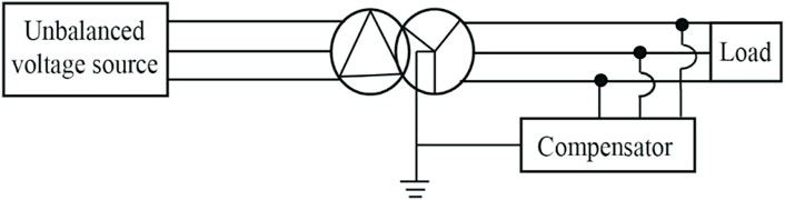
FIGURE 1. Power network with unbalanced voltage source.
The corresponding three-phase equivalent diagram of Figure 1 is given in Figure 2, where

FIGURE 2. Schematic diagram of the equivalent test system.
It is assumed that the power network and the step-down transformer is represented by unbalanced three-phase voltage source with the neutral point connected to ground (directly or through impedance) as shown in Figure 2.
2.1 Line-line voltage balancing
In the following, a novel voltage balancing method is proposed based on the phasor symmetrical component theory. According to the symmetrical component theory, the three phase load voltages can be decomposed as
where
If the difference of the negative sequence components, i.e.,
2.2 Exhaustive search solution
In the exhaustive search solution, each phase of the compensator consists of n number of parallel reactors controlled by the mechanical switches, as shown in Figure 3. The impedance values of the reactors in each phase are given as m, 2
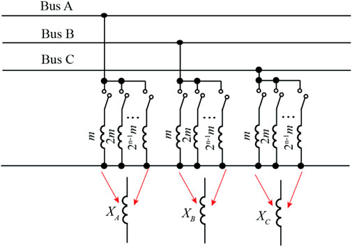
FIGURE 3. Exhaustive search solution.
2.3 Exact analytical solution
2.3.1 No-load scenario
In this subsection, the exact analytical solution of the compensator for no-load scenario is derived. When the system given in Figure 2 is operated without any load, it can be decoupled into three single phase equivalent circuits to facilitate the compensator impedance solution. The load voltage of each phase is given by
Thereby, the negative sequence component of phase A can be calculated by
where
2.3.2 Loaded scenario
For the loaded scenario, as shown in Figure 2, the three-phase circuit cannot be decoupled. Without loss of generality, the three-phase asymmetrical load is represented by three-phase impedances of
where
The compensator reactances, i.e.,
2.3.3 Degree of freedom
As
Compared to the exhaustive search method, the results of the analytical solution can produce smaller negative sequence component and thus the voltage quality is better. However, the values of the compensating reactors need to be updated when the unbalanced voltage source and the load vary.
Normally recognizing
3 Article types
The exact analytical solution, introduced in the previous section, require to solve 2 × 2 nonlinear equations from Eqs 10, 12. Numerical solution methods, for example, Newton-Raphson or Gauss-Seidel method can be used to solve them iteratively. However, this increase the computational burden of the digital control hardware of the compensator. In this section, a novel simplified analytical solution is proposed to avoid the solution of nonlinear equations for the compensator design. This simplified solution is based on the relationship between the negative sequence source voltage before compensation and zero-sequence load voltage after compensation. The simplified analytical solution is derived based on no-load scenario since the analytical solution of the loaded scenario is very similar to the unloaded scenario due to
3.1 Relationship between negative sequence source voltage and zero sequence load voltage
As discussed in Section 2.3.3, only two-phase compensation reactors are required. Without loss of generality, it is assumed that the compensators are installed on phases A and B. Assuming the zero-sequence component of
with
and
In Eqs 15–17,
The zero-sequence voltage
Substituting (15)−(17) into (20) yields
As
The negative sequence load voltage,
From (23), the relationship between
As
Comparing (25) with (12), it can be observed that the real part of
where the superscript ‘
3.2 Compensator design using simplified analytical solution
In this subsection, a simplified analytical solution based on the relationship between
1) Without loss of generality, it is assumed that the compensation reactors are installed at both phases A and B.
2) Calculating the zero sequence load voltage
3) Since phase C is not compensated and negative sequence load voltages
4) Deriving the positive sequence load voltages of phases A and B, based on the positive sequence load voltage
5) Synthesizing the load voltages of phases A and B from their symmetrical components as
6) Determining the compensator impedance values of phases A and B under no-load scenario as
7) The compensator reactances of phases A and B are solved by taking the imaginary parts of Eqs 32, 33 as
It is noted that compared with the analytical solution of (10) or (12), the simplified analytical solution does not need to solve any nonlinear equations. Thus, the calculation burden of the digital control platform of the compensator is greatly reduced.
4 Compensator implementation using line commutated converter
In this section, the line commutated converter (LCC) is implemented to compensate the unbalanced voltages instead of the MSR, as introduced in Section 2 and Section 3. As a well-proven technology, thyristor controlled reactor (TCR) is used for the compensator implementation. Comparing with MSR proposed in Section 2, TCR has the advantage that the equivalent reactance value is continuous and can be updated conveniently with the changing system conditions.
The single-phase circuit topology of TCR is illustrated in Figure 4 (IEEE Special Stability Controls Working Group, 1994)− (Flores et al., 2009), which mainly comprises of a pair of thyristors and a reactor.
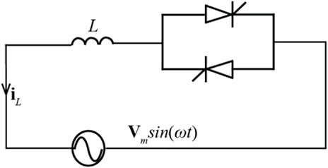
FIGURE 4. Single-phase circuit topology TCR.
It is noted that the detailed derivation.
With the detailed derivation in the Appendix, the equivalent fundamental frequency reactance
where
5 Compensator implementation using voltage source converter
The two-phase VSC to compensate the unbalanced voltage is shown in Figure 5. The advantage of the VSC is that it has smaller low order harmonics when compensating the grid voltage. Without loss of generality, it is assumed that a full-bridge converter is used as a two-phase VSC. The full-bridge converter can be installed at two arbitrary phases of the grid. In Figure 5, it is assumed that the VSC is installed at phases A and B. Both open-loop and closed-loop controls are designed to regulate the output voltage of the VSC so that the grid voltage at the load terminals are balanced.
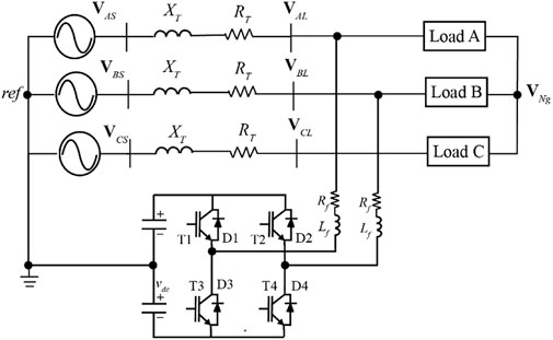
FIGURE 5. Single-line electric diagram of a compensated system using VSC.
For the open-loop control, the substitution principle is employed. To be more specific, the compensated load voltages (
1) The equivalent reactance values elaborated in Section 2 or Section 3 are calculated.
2) Employing the substitution principle, the compensated load voltages
3) Finally, the AC voltage references,
where
In order to increase the accuracy and flexibility of the proposed method, closed-loop control is also designed. The negative-sequence voltage of phase A is the input of the PI controller and the output of the PI controller is added to the amplitude of VSC AC output voltage reference. The closed-loop control can flexibly deal with some unprepared disturbances such as load and source voltage variations.
6 Simulation studies
The simulation system, as shown in Figure 1, chosen for the case studies is based on the power quality correction project for Martabe Gold Mine carried out by the Struthers Technical Solutions Ltd. (StruthersTech). Metering was performed on the 150 kV busbars at the Martabe substation, between Sibolga and Padang Sidempuan. The parameters of the equivalent circuit in Figure 2, the value of the inductor, i.e., L, of TCR in Figure 4 and the
TABLE 1. Parameters of the equivalent circuit of the martabe gold mine.
6.1 Case A: Exhaustive search solution using MSR
In the project of Power Quality Correction for Martabe Gold Mine, the Struthers Tech designed the exhaustive search solution using combinations of discrete inductor components to compensate the unbalanced voltages. The proposed compensators will be connected directly to the secondary terminals of the 150/11 kV power transformers. Each is connected in a 4-wire configuration, with a fully insulated neutral bus connected via cable. The load is mostly induction motor type, all fed from 11 kV step-down transformers having a primary Delta connection.
As shown in Figure 6, each phase of the proposed compensator is composed of three MSRs in parallel with the three inductors of 0.08 H, 0.16 H, and 0.32 H. Thereby, there are 512 values of the equivalent compensators according to Section 2.2. Exhaustive search method is applied to find the desirable combination of MSRs, which yields the minimum negative sequence component of the load voltage. According to the calculated results, the optimal combination of MSRs is infinite for A phase (Compensator of phase A is not connected), 0.0457 H for B phase (all of the MSRs are connected), and 0.064 H for C phase (MSRs with the values of 0.08 H and 0.32 H are connected).
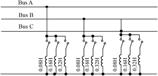
FIGURE 6. Basic three-line arrangement of the proposed compensator.
The negative sequence voltage before and after compensation over a 12-h time period is shown in Figure 7, which is a practical field result recorded by the StruthersTech. It can be seen from Figure 7 that, the negative sequence voltage on the uncompensated 11 kV bus without compensation can be up to nearly 0.7%. With the compensator designed by the StruthersTech in service, the negative sequence imbalance on the compensated 11 kV bus is reduced to less than 0.2%.
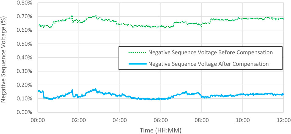
FIGURE 7. Negative-sequence voltage before and after compensation.
6.2 Case B: Exact analytical solution using MSR and TCR
For the analytical solution, the lower bound of the compensator of each phase is defined to be 0.0437H and the upper bound is infinite. The Matlab function “fmincon” can be used to solve this optimization problem by setting
6.2.1 No-load condition using MSR
According to Eq. 10 in Section 2.3.1, the analytical compensator value calculated by the fmincon function is infinite for A phase, 0.0486 H for B phase, and 0.0560 H for C phase. The negative sequence voltage is minimized from 80.64 V (1.24%) before compensation to 0.216 V (0.003%) after compensation by the analytical solution. The voltage waveforms on 11 kV bus before and after compensation is shown in Figure 8A,B respectively. From Figure 8B it can be observed that, the three-phase voltage waveforms after compensation is much more balanced than those before compensation as shown in Figure 8A.
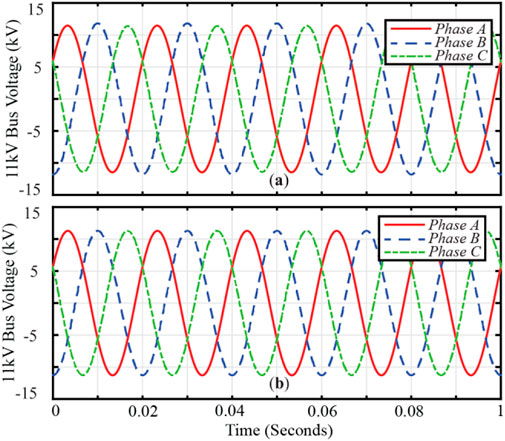
FIGURE 8. Three-phase voltage waveforms on 11 kV bus before and after compensation. (A) Three-phase voltage waveforms before compensation. (B) Three-phase voltage waveforms after compensation.
6.2.2 Loaded condition using MSR
For the loaded condition, ten successive moments of the 11 kV bus with the unbalanced full-loaded loads are compensated using the analytical solution elaborated in Section 2.3.2. The resistive unbalanced loads over ten successive moments are given in Table 2. The analytical values of the compensator installed on phases B and C and negative sequence voltage after compensation are given in Table 3. From Table 3 it can be seen that the values of compensator under loaded condition are close to the compensator value of the unloaded condition.
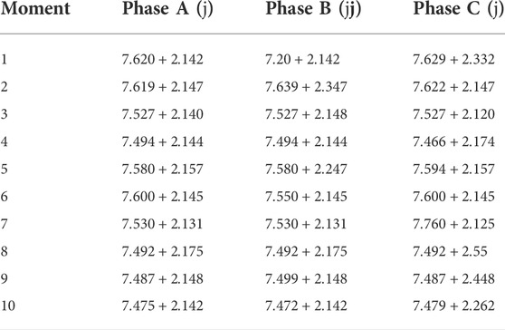
TABLE 2. Ten unbalanced loads (
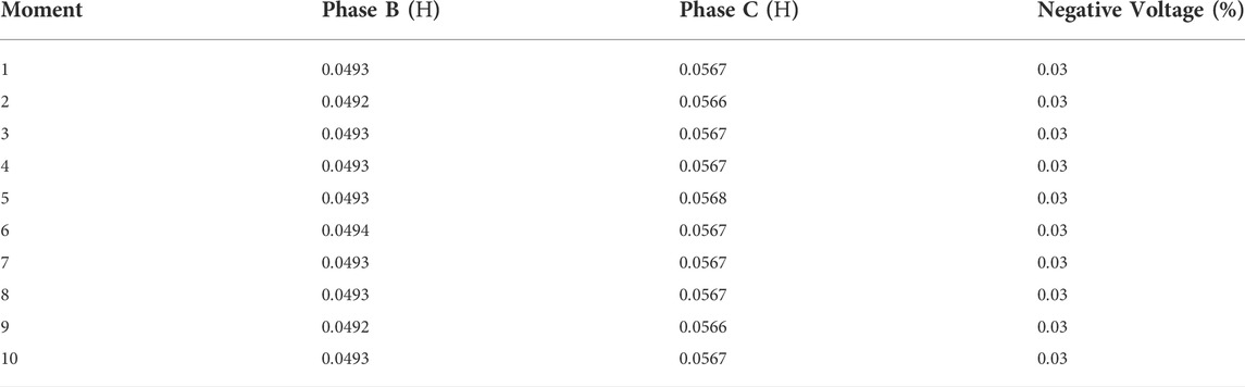
TABLE 3. Analytical compensator values and negative sequence voltage after compensation.
6.2.3 Analytical solution using TCR
Similar to the MSRs in Case 6.2.1, TCRs are installed on B phase and C phase. Applying the method elaborated in Section 4, the conduction angles
6.2.4 Case C: Simplified solution using VSC
Applying the simplified solution in Section 3, the inductances of the compensators in phase B and phase C are 0.0479 H and 0.0550 H, respectively. While the analytical calculation results of the inductance values are 0.0486 H for phase B and 0.0560 H for phase C. It can be seen that the simplified calculation result of the compensator is quite close to the analytical result. But the simplified solution does not need to solve the nonlinear equations so that it is easier to be implemented and has less computational burden.
After following the corresponding steps in Section 5, the amplitudes and phase angles for the AC voltage modulating indexes of phase B and phase C are given in Table 4.
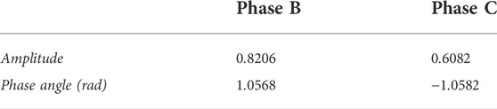
TABLE 4. Amplitudes and phase angles for the AC output voltage references of phases B and C.
From the simulation result, the negative-sequence voltage after compensated by the two-phase VSC is reduced to 1.444 V (0.021%). In addition, the AC-side current of the VSC installed on phase B is shown on Figure 8. From Figure 9 it can be seen that, the amplitude of the AC-side current is around 420 A.
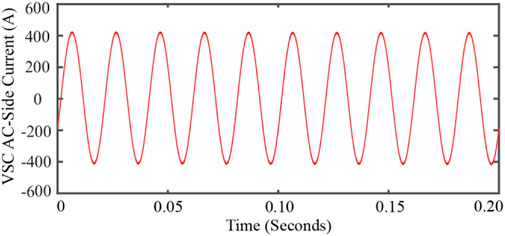
FIGURE 9. AC-side current of the VSC installed on phase B.
7 Conclusion
In this work, a novel algorithm for two-phase voltage balancing compensator is proposed based on the phasor symmetrical component theory, which can be applied to MSRs, TCRs or VSCs. The proposed two-phase compensator can greatly reduce the investment cost compared to the traditional three-phase compensator. Three methods are proposed to calculate the value of the proposed two-phase compensator, i.e. discrete solution, analytical solution and novel simplified solution. The discrete solution has been proven in a field application by StruthersTech in the project of PLN Power Quality Correction for Martabe Gold Mine and is very easy to be implemented. The novel simplified solution can avoid calculating the nonlinear equations of the analytical solution, which can greatly reduce the calculated burden. The field work results as well as the dynamic simulations implemented with MATLAB/Simulink Simscape Blockset validate the accuracy and the effectiveness of the proposed two-phase voltage balancing method. It is noted that the proposed method can be used in both transmission system and distribution system with various topologies. The limitation of the proposed two-phase balancing method is that it cannot compensate the distorted voltage. Thus, the load compensation techniques under distorted voltages will be our future work.
Data availability statement
The original contributions presented in the study are included in the article/Supplementary Materials, further inquiries can be directed to the corresponding author.
Author contributions
YZ, CS, and LW contributed to the conception and design of the algorithm and case study. YZ and LW wrote the first draft of the manuscript. QH contributed to manuscript revision and proofread and approved the submitted version.
Funding
This research is supported by the National Natural Science Foundation of China (51907026), Natural Science Foundation of Jiangsu Province, China (BK20190361), Key Research and Development Program of Jiangsu Province, China (BE2020081-2).
Acknowledgments
The authors would like to thank the National Natural Science Foundation of China (51907026), Natural Science Foundation of Jiangsu Province, China (BK20190361), Key Research and Development Program of Jiangsu Province, China (BE2020081-2).
Conflict of interest
The authors declare that the research was conducted in the absence of any commercial or financial relationships that could be construed as a potential conflict of interest.
Publisher’s note
All claims expressed in this article are solely those of the authors and do not necessarily represent those of their affiliated organizations, or those of the publisher, the editors and the reviewers. Any product that may be evaluated in this article, or claim that may be made by its manufacturer, is not guaranteed or endorsed by the publisher.
References
Akagi, H., Ogasawara, S., and Kim, H. (1999). The theory of instantaneous power in three-phase four systems: a comprehensive approach. Proceeding. 34th Ind. Appl. Conference., Ind. Appl. Soc Annual Meeting, Phoenix, AZ, USA, Oct. 3–7 1, 431–439.
Alkayyali, M., and Ghaeb, J. (2019). Hybrid PSO–ANN algorithm to control TCR for voltage balancing, ” IET Generation. Transm. Distribution 14 (5), 863–872.
Chen, T., Pipattanasomporn, M., Rahman, I., Jing, Z., and Rahman, S. (2020). MATPLAN: A probability-based planning tool for cost-effective grid integration of renewable energy. Renew. Energy 156, 1089–1099. doi:10.1016/j.renene.2020.04.145
Escobar, G., Mattavelli, P., and .Stankovic, A. M. (2001). Reactive power and unbalance compensation using STATCOM with dissipativity-based control. IEEE Trans. Control Syst. Technol. 9, 718–727.
Flores, P., Dixon, J., Ortuzar, M., Carmi, R., Barriuso, P., and Moran, L. (2009). Static Var compensator and active power filter with power injection capability, using 27-level inverters and photovoltaic cells. IEEE Trans. Ind. Electron. 56 (1), 130–138. doi:10.1109/tie.2008.2009513
Fuchs, E. F., and Masoum, M. A. S. (2008). Power quality in power systems and electrical machines. San Diego, CA: Academic.
Ghosh, A., and Ledwich, G. (2002). Compensation of distribution system voltage using DVR. IEEE Trans. Power Deliv. 17 (4), 1030–1036. doi:10.1109/tpwrd.2002.803839
Hu, Q., Han, R., Quan, X., Wu, Z., Tang, C., Li, W., et al. (2022a). Grid-forming inverter enabled virtual power plants with inertia support capability. IEEE Trans. Smart Grid, 1. doi:10.1109/TSG.2022.3141414
Hu, Q., Liang, Y., Ding, H., Quan, X., Wang, Q., and Bai, L. (2022b). Topological partition based multi-energy flow calculation method for complex integrated energy systems. Energy 244, 123152. doi:10.1016/j.energy.2022.123152
IEEE Special Stability Controls Working Group (1994). Static VAR compensator models for power flow and dynamic performance simulation. IEEE Trans. Power Syst. 9, 229–240.
Kazmierkowski, M. P. (2007). Power quality: Mitigation technologies in a distributed environment. Berlin: Springer Science & Business Media.
Lee, K., Jahns, T. M., Berkopec, W. E., and Lipo, T. (2006). Closed-form analysis of adjustable-speed drive performance under input-voltage unbalance and sag conditions. IEEE Trans. Ind. Appl. 42 (3), 733–741. doi:10.1109/tia.2006.872953
Lee, S. Y., and Wu, C. J. (2000). Reactive power compensation and load balancing for unbalanced three-phase four-wire system by a combined system of an SVC and a series active filter. IEE Proc. Electr. Power Appl. 147 (6), 563–578. doi:10.1049/ip-epa:20000722
Mi, Y., Ma, C., Fu, Y., Wang, C., Wang, P., and Loh, P. C. (2018). ‘The SVC additional adaptive voltage controller of isolated wind-diesel power system based on double sliding-mode optimal strategy. IEEE Trans. Sustain. Energy 9 (1), 24–34. doi:10.1109/tste.2017.2713700
Mishra, M. K., Ghosh, A., Joshi, A., and Suryawanshi, H. M. (2007). A novel method of load compensation under unbalanced and distorted voltages. IEEE Trans. Power Deliv. 22 (1), 288–295. doi:10.1109/tpwrd.2006.881579
Mishra, M. K., Joshi, A., and Ghosh, A. (2001). A new compensation algorithm for balanced and unbalanced distribution systems using generalized instantaneous reactive power theory. Electr. Power Syst. Res. 60, 29–37. doi:10.1016/s0378-7796(01)00166-3
Muljadi, E. (1984). Induction machine phase balancing by unsymmetrical voltage control. Madison: University of Wisconsin.
Muljadi, E., Batan, T., Yildirim, D., and Butterfield, C. P. (1999). “Understanding the unbalanced voltage problem in wind turbine generation,” in Conf. Rec. IEEE IAS Annu. Meeting, Phoenix, AZ, USA, 03-07 October 1999, 1359–1365.
Omar, R., and Rahim, N. A. (2012). Voltage unbalanced compensation using dynamic voltage restorer based on super capacitor. Int. J. Electr. Power & Energy Syst. 43, 573–581. doi:10.1016/j.ijepes.2012.05.015
Peng, F. Z., and Lai, J. S. (1996). Generalized instantaneous reactive power theory for three-phase power systems. IEEE Trans. Instrum. Meas. 45 (1), 293–297. doi:10.1109/19.481350
Sadigh, A. K., and Smedley, K. M. (2012). “Review of voltage compensation methods in dynamic voltage restorer (DVR),” in Proceedings of the IEEE Power Energy Soceity General Meeting, San Diego, CA, USA, 22-26 July 2012, 1–8.
Struthers, C. Three phase load balancing and power factor correction using a pulse width modulated static compensator. MS thesis. 2001.
Sun, L. Y., Tong, S., and Liu, Y. (2011). Adaptive backstepping sliding mode $H_{\infty} $ control of static var compensator. IEEE Trans. Control Syst. Technol. 19 (5), 1178–1185. doi:10.1109/tcst.2010.2066975
Wang, Y. J. (2001). Analysis of effects of three-phase voltage unbalance on induction motors with emphasis on the angle of the complex voltage unbalance factor. IEEE Trans. energy Convers. 16 (3), 270–275. doi:10.1109/60.937207
Wei, C., Zhao, Y., Zheng, Y., Xie, L., and Smedley, K. (2022). Analysis and design of a non-isolated high step-down converter with coupled inductor and ZVS operation. IEEE Trans. Ind. Electron. 69 (9), 9007–9018. doi:10.1109/tie.2021.3114721
Woll, R. F. (1975). Effect of unbalanced voltage on the operation of polyphase induction motors. IEEE Trans. Ind. Appl. 11, 38–42. doi:10.1109/tia.1975.349255
Xiao, D., Chen, H., Wei, C., and Bai, X. (2021). Statistical measure for risk-seeking stochastic wind power offering strategies in electricity markets. J. Mod. Power Syst. Clean Energy.2021. doi:10.35833/MPCE.2021.000218
Appendix A:
The triggering points of the thyristors are given by
where
The current flowing through the inductor is calculated by
The general solution of Eq. 33 is written by
where K is the integration constant.
It is noted that
It is noted that the current becomes zero again at
where
Appling Fourier analysis to the reactor current, the amplitude of the fundamental frequency component is formulated as
Then the instantaneous value of fundamental wave is
The conduction angle
Keywords: mechanically switched reactors (MSRs), novel simplified method, thyristor controlled reactors (TCRs), voltage compensation, voltage source converters (VSCs), negative sequence compensation, zero sequence compensation
Citation: Zhang Y, Wang L, Struthers C and Hu Q (2022) A novel two-phase load compensation method under unbalanced voltages for renewable energy integration. Front. Energy Res. 10:1013585. doi: 10.3389/fenrg.2022.1013585
Received: 07 August 2022; Accepted: 22 August 2022;
Published: 13 September 2022.
Edited by:
Dongliang Xiao, South China University of Technology, ChinaCopyright © 2022 Zhang, Wang, Struthers and Hu. This is an open-access article distributed under the terms of the Creative Commons Attribution License (CC BY). The use, distribution or reproduction in other forums is permitted, provided the original author(s) and the copyright owner(s) are credited and that the original publication in this journal is cited, in accordance with accepted academic practice. No use, distribution or reproduction is permitted which does not comply with these terms.
*Correspondence: Yuanshi Zhang, eXVhbnNoaXpoYW5nQHNldS5lZHUuY24=