 Muhammad Adnan Samad1
 Yuanqing Xia1*
 Tayyab Manzoor2Kashif Mehmood3Adeel Saleem3
 Ahmad H. Milyani4Abdullah Ahmed Azhari5
- 1Key Laboratory of Intelligent Control and Decision of Complex Systems, School of Automation, Beijing Institute of Technology, Beijing, China
- 2School of Automation Science and Engineering, South China University of Technology, Guangzhou, China
- 3Department of Electrical Engineering, Fergana Polytechnic Institute, Fergana, Uzbekistan
- 4Department of Electrical and Computer Engineering, Center of Research Excellence in Renewable Energy and Power Systems, King Abdulaziz University, Jeddah, Saudi Arabia
- 5The Applied College, King Abdulaziz University, Jeddah, Saudi Arabia
This article compares the conventional model predictive control (MPC) and active disturbance rejection control (ADRC) with a novel MPADRC technique for controlling a non-minimum phase behavior in the DC–DC boost converter. The control of the boost converter is challenging as it is nonlinear, and it shows non-minimum phase behavior in a continuous conduction mode (CCM). Moreover, in this article, the comparison is presented for the boost converter and the two-phase interleaved boost converter using MPC and ADRC, and the effectiveness of the interleaving technique is shown. Finally, it is proved that the interleaving method has much more efficiency and less output ripple than the simple boost converter. To conclude, a novel technique has been introduced that combines both the techniques, that is, MPC and ADRC, in the outer and inner loop with a boost converter, respectively, and the response is clearly the best when compared to the said techniques individually. The overall impact of this technique includes the advantages of both the techniques, that is, the use of MPC allows us to optimize the current value by predicting the future values, and the use of ADRC ensures that the disturbance factor is well tackled and cancels the effect caused by all the disturbances including ignored quantities as well.
1 Introduction
1.1 Literature review
Boost converters are mainly used to get a higher regulated output voltage from a lower unregulated input voltage. To implement it and fully understand its step response, first, the simple boost converter is implemented in MATLAB using a state space model and analyzed. Upon analysis, the step response parameters, that is, rise time, settling time, percentage overshoot, and steady-state error are found to be highly undesirable, so there should be a technique, that is, a controller that should be used in conjunction with a boost converter to make its step response parameters better. In search of a controller, initially, PID (proportional integral derivative), PD, and PI controllers were found to be appropriate and used, but later on, the results, that is, step response parameters obtained using PID, PD, and PI, were also found to be the non-optimal ones, so the search for a better controller continued. Finally, MPC (model predictive controller) and ADRC (active disturbance rejection control) were found to be the best among all, while PID did not consider the future associations of the current control strategies. On the other hand, MPC unambiguously computes the predicted output over some horizon. The control of simple boost converters using the unconstrained nonlinear optimization technique to tune the parameters of PID is an advancement as compared to conventional techniques in many research articles but still has a chance to increase the efficiency. In recent days, there have been many research studies that cover all of these advancements. Nowadays, MPC is considered a new control technique for DC–DC converters. It can be used to obtain a better step response and step response parameters. The main theme of MPC is to predict future output by looking into present or past input values (Murali et al., 2010; Rossiter, 2022).
Recently, many used techniques incorporate detailed mathematical modeling to control these types of converters, but the need of the hour is to explore some other techniques as well that can predict, estimate, and reject the future disturbances (Chen et al., 2016) as ADRC. It was first introduced and discovered by Han (1999) and Han (2009) to work on both internal and external disturbances by estimating their mutual effect via an ESO (extended state observer), and much literature is presented on the said technique (Zhou et al., 2009; Zheng et al., 2012; Huang and Xue, 2014; Madoński and Herman, 2015; Feng and Guo, 2017). ADRC is also used recently to control these types of converters, and there have been different ADRC techniques from linear to high control gain and generalized ADRC (Saif and Ahmad, 2019).
State space representation is the most used representation for DC–DC converters to implement their step response, especially in MPC. First, the control problem is formulated, and then it is taken as the optimal problem to solve it using a predictive controller. The main objective is to regulate the output voltage despite changes in the input voltage or load resistance (Wang, 2009). Although the boost converter is very useful in many power applications, the interleaving technique has also become more effective than a simple boost converter. Basically, an interleaved boost converter is made by combining more than one boost converter. Moreover, the interleaving method is more suitable than the simple boost converter topology. The main objectives of interleaving are to improve the efficiency, reduce the component size, and reduce the current ripple and obviously the transient response. The benefits of interleaving are high power ability, improved efficiency, modularity, reduced size, and reliability, but there is a trade-off that the number of overall components will be increased (Kosai et al., 2009). The poor dynamic response caused by the use of conventional PI control requires a voltage feedforward compensator with MPC (Li et al., 2017; Li et al., 2018). To overcome this problem, the advanced technique ADRC is proposed in this work.
As compared to low-power applications, the use of interleaving for high-power applications has many advantages like increasing the output power and decreasing the output ripple, but the current sharing between the parallel paths is really worth considering (Lee et al., 2000).
The interleaving technique has many more advantages as compared to a conventional boost converter, that is, a slight modification in an interleaved boost converter can result in a voltage gain far better than a conventional boost converter (Gustavo et al., 2010). With these features, the interleaved boost converter is considered the best converter used in many applications. It is most suitable where a large step-up power is demanded in which the renewable energy resource application is on the top list.
Some more applications of the interleaving technique include high-power applications. It is a multidevice interleaved boost converter (MDIBC) that basically forms an interface between fuel cells and hybrid electric vehicles. The main advantages of this technique include the reduction of input ripple current, the ripples of output voltage, and finally the size of the passive components with high efficiency as compared to the other available techniques (Omar et al., 2012). Moreover, the interleaving technique can include a minimum of two boost converters in parallel up to n, where n can be any integer level according to the requirements of the controller and plant.
Some more optimization techniques like predictive function control can be used to regulate the temperature-efficient energy consumption (Nassima et al., 2021). Furthermore, the limitation of a proportional integral (PI) controller can be resolved by using some advanced expert approaches (Ahmed et al., 2022; Kim et al., 2014). For tuning the control parameters, there is a need for advanced optimization techniques so that we can get better system response parameters (Khan et al., 2022). Finally, the comparison of PID and ADRC is presented in Han (2009), which clearly shows the effectiveness of ADRC on PID and its shortcomings.
1.2 Contribution
While talking about DC converters, specifically a non-minimum phase system like boost converters, much work has been carried out in terms of its use in stepping up techniques and its control using conventional and some advanced techniques. In this work, the two-way approach has been used; first, not only the boost converter but also the two-phase boost converter is used to attain maximum efficiency. Second, the proposed work uses two control techniques, namely, the MPC and the ADRC, in the outer and inner loops, respectively. The results clearly show that controlling these types of converters alone by using any technique has less efficiency as compared to using a novel MPADRC technique.
1.3 Organization and notations
The article is organized in the following way: Section 1 gives the introduction and literature review. Section 2 covers the detailed mathematical modeling of boost and interleaved boost converters. Section 3 briefly states the problem that is going to be solved. Section 4 outlines the control and design approach opted for this research. Finally, the simulation is presented in Section 5 which shows and proves the effectiveness of this proposed controller design. In the end, the conclusion and future work are presented in Section 6.
2 Mathematical modeling
2.1 Mathematical modeling of the DC/DC boost converter
The basic circuit diagram of a DC/DC boost converter, which can enhance the voltage level, is shown in Figure 1. The basic topology consists of a voltage source, an inductor, a switch, a diode, and a capacitor with an output load in parallel. There can be different possibilities to implement this type of converter (reference). Some techniques (reference) can easily handle its both modes of conduction, that is, CCM and DCM, and some have only taken CCM for the sake of simplicity (reference). This research only includes CCM for the sake of simplicity. In addition, the parasitic resistances for both the inductor and capacitor are also included. The different states associated with the DC/DC boost converter are shown in Figures 2, 3, representing the ON state and OFF state, respectively. During the ON state, the inductor current increases, and during the OFF state, this inductor current decreases to fulfill the load requirements. Initially, KCL and KVL have been used to formulate the basic current and voltage equations, and then, for averaging, the state space modeling is being used and expressed as follows:
where
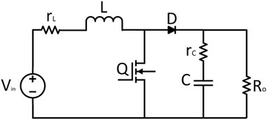
FIGURE 1. DC/DC boost converter.
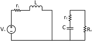
FIGURE 2. ON state.
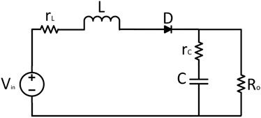
FIGURE 3. OFF state.
Finally, averaging and combining the state space representation for ON time and OFF time as given in the following equation, A = A1d + A2(1 − d), B = B1d + B2(1 − d), C = C1d + C2(1 − d), and D = D1d + D2(1 − d), yield
where vin is the input voltage, vc is the voltage across the capacitor, vo is the output voltage, iL is the inductor current, L is the inductance, C is the capacitance, and R is the load resistance.
2.2 Mathematical modeling of the DC/DC interleaved boost converter
2.2.1 Two-phase interleaved boost converter
Nowadays multiphase converter topologies are in high demand as they can be very useful, especially in high-performance applications. This research work includes the interleaving technique to increase efficiency and reduce the input and output ripples as compared to simple topologies. Moreover, improvement in switching stress and low EMI can also be achieved. Starting from two to n boost converters, they can be connected in parallel to form an n-phase interleaved boost converter. Initially, a two-phase interleaved boost converter is presented in detail with two switches and four states.
The basic circuit diagram of a two-phase interleaved DC/DC boost converter is shown in Figure 4. The basic topology consists of two boost converter stages in parallel. Again, the CCM for the sake of simplicity is being taken into consideration, and the parasitic resistances for both the inductor and capacitor are also included.
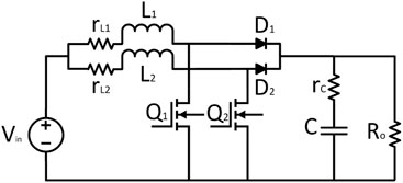
FIGURE 4. Two-phase interleaved boost converter.
The different states associated with the DC/DC boost converter are shown in Figures 5–8 representing the four states, respectively. Then, using basic rules of KCL and KVL and depending upon switch states, the current and voltage equations of all states have been formulated, and the average state space is modeled as follows, while the matrices A1, A2, A3, A4, and B of all four states, respectively, are given by
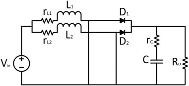
FIGURE 5. Q1 and Q2 are ON.
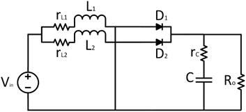
FIGURE 6. Q1 is ON and Q2 is OFF.

FIGURE 7. Q1 is OFF and Q2 is ON.
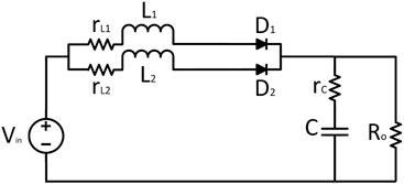
FIGURE 8. Q1 and Q2 are OFF.
Finally, averaging and combining the state space representation for all the states using
A = [A1 + A3]*d + [A2 + A4]*(1/N − d) yields
where vin is the input voltage, vc is the voltage across the capacitor, vo is the output voltage,
3 Problem statement
While talking about DC/DC converters, the output should regulate to follow the given reference, while the input voltage or the output load keeps changing. In the presented case of the boost converter and interleaved boost converter, the input to the converter is the unregulated DC voltage, and the output is the regulated DC voltage. One more prominent and challenging factor while controlling these types of converters is its non-minimum phase behavior that tries to destabilize the close loop response due to the right half plane zero in its transfer function, which is mainly because of the inductor attached to the input. This specific type of system shows an inverse phenomenon as the output initially moves in the opposite direction of the reference (Forouzesh et al., 2017). In many practical applications, the uncertainties in different parameters, especially ESR contributes to the poor performance, and the importance of ESR (effective series resistance) in DC boost converters is detailed in Yao et al. (2016). The steady-state error due to ESR of an inductor is more prominent than that due to the ESR of a capacitor. In short, the main objective of this study is to regulate the output voltage under input and load variations as quickly as possible while eliminating the steady-state error using model predictive control along with ADRC.
4 Control and design approach
This section incorporates the controller and its novel design while using the model predictive controller and ADRC in the outer and inner loops, respectively. The detailed control diagram is shown in Figure 9. Initially, an objective function is defined, and then this function is minimized based on the control law techniques. As it can be seen in the figure, the control includes two loops: the inner ADRC loop for tracking the current to its reference and the outer MPC loop for producing a reference current. Thus, the ADRC scheme for the inner loop is designed to track the current according to limk→∞iL(k) = iref, while the outer loop is an addition to further tune the response by taking the collective advantage of ADRC and MPC. For stability check and to see the effectiveness of the proposed controller, the Bode diagram of the plant without any controller and with an MPADRC controller is analyzed in Figure 10. The Bode diagram of the DC–DC boost converter without any controller is shown in Figure 10A, and the Bode diagram of the said converter with the proposed controller is shown in Figure 10B.
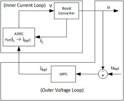
FIGURE 9. Main control approach.
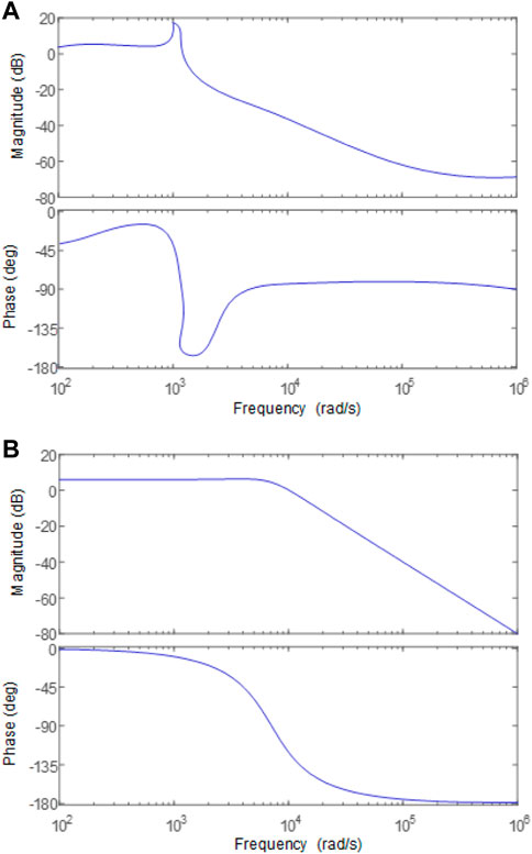
FIGURE 10. (A) Bode diagram without a controller. (B) Bode diagram with a controller.
4.1 Model predictive controller
The standard MPC technique solves a finite horizon problem and an optimal control problem based on a linear prediction model of the process (Bemporad et al., 2002; Mayne, 2014). In the field of power supplies, the use and interest of MPC keep growing as it has the ease of handling multivariable systems, introducing input/output constraints, and an intuitive design process (Vazquez et al., 2014; Karamanakos et al., 2014). Moreover, the MPC is an efficient control technique that works on the principle of receding horizon control (Belda and Vosmik, 2016; Judewicz et al., 2016). The major benefits of MPC include the following: it can control the MIMO system, it can well handle the input/output constraints, and it can make an advanced prediction of the model response. For all the aforementioned benefits, the applications of MPC have been investigated in different sectors such as power electronic converters, aerospace, renewable energy, and food processing. (Vazquez et al., 2014; Anang and Leksono, 2016; Raziei and Jiang, 2016; Zhao et al., 2017). A general block diagram of MPC is shown in Figure 11.
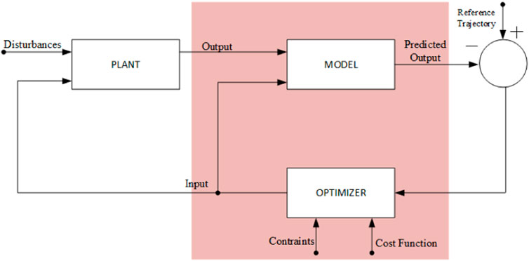
FIGURE 11. MPC block diagram.
In this work, the MPC scheme is proposed in the outer loop, especially to control the current for controlling the DC–DC boost and multistage interleaved boost converters. The main purpose of using MPC is to control the output voltage by controlling the switch.
The main procedure of MPC is to formulate an objective function according to system dynamics and constraints and then minimize at each step over a set prediction horizon, which increases by one sampling interval at each step.
4.2 Active disturbance rejection control
Active disturbance rejection control (ADRC) is first introduced by Jingqing Han in the 1980s as an unconventional design strategy. Since then, it has been considered an effective control strategy in the absence of proper models and in the presence of model uncertainty. Its effectiveness is shown in Han (2009) over conventional PID. In this study, ADRC is implemented in the inner loop to control the voltage of these DC converters and to generate a current reference to further feed into the inner loop for current tracking. The disturbance on load basically brings an error to the input in summer with the reference value, and then ADRC is applied to correct the error by adjusting its parameters as shown in Figure 12, where y is the output of the ADRC control and z is the estimates of different states. The nominal model used in this case can be of the nth order, where n is the order of the system to be controlled. The need of the hour is to check the deviation from the nominal suggested structure, and each and every deviation will be considered a disturbance. The extended state observer (ESO) is used to estimate the state and the “total disturbance.”
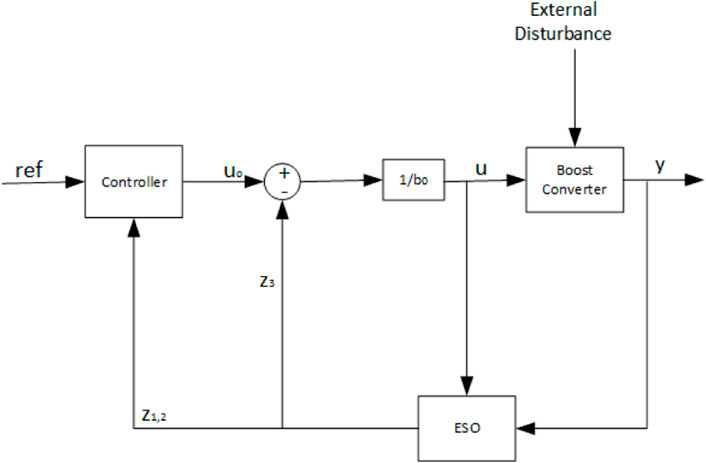
FIGURE 12. Structure of the ADRC.
4.3 Objective function
This is the main part in controlling any type of plant. When working on the objective function, the deviation should be well taken care of for the variables from the predicted value to the desired value over the set horizon N. The input to be controlled at any time instant kTs can be easily obtained by minimizing the particular function while taking into consideration the optimization variable, that is, specifically, the sequence of switching states over the entire horizon U(k) = [u(k)u(k + 1)…u(k + N − 1)]T. Thus, the optimal solution is represented by U* which can be calculated by minimizing the objective function; u*(k) is applied at the input of the converter and used as the first element of the whole sequence. This procedure is repeated at the consecutive sampling instants based on the newly measured values, and the remaining elements are discarded. In this work, the control problem is obtained and formulated as a current regulation problem, which mainly accounts for the deviation of the inductor current from its set reference, which is defined as follows:
While working on these types of objective functions, there can be several possibilities to describe the error, that is, the average value of the current or the RMS value of the current can be considered. In this particular work, the average current error is used as described in the following section.
4.3.1 Average current error
At any particular time-step k, the average current error over the prediction interval N*Ts can be represented by
Using the fact that the current slope remains constant in between the sampling instants and changes only at the sampling instants, the aforementioned integral can be rewritten as follows:
Based on these equations, the objective function can be written as follows:
4.4 Optimization problem
After describing the objective function, the optimization problem can be formulated and solved at each sampling instant, and it has the form,
subject to the mathematical model of the converters. The aforementioned optimization problem is solved using these possible combinations of the switching state, that is, (u = 0 or u = 1) over the entire prediction horizon N, which yields the switching sequences U. For each switching sequence, that is, 2 power N, the evolution of the variables of concern is formulated, and the objective function is evaluated. The most cost-effective switching sequence is chosen as the optimal one, U*. Hence, the control input at time-step k is obtained by minimizing the corresponding objective function, and it is given by
5 Simulation results
To investigate the effectiveness of the proposed novel MPADRC, the following simulations in the presence of disturbances are carried out. The initial values of all the parameters are shown in Table 1, and the target condition is to track the set point value with less overshoot and improved steady-state error.
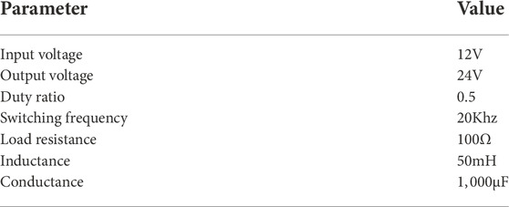
TABLE 1. Initial values.
To show the effectiveness of the proposed MPADRC scheme, the input also includes the disturbance parameter in Figure 14. Also, the respective output is shown in Figure 13. The effectiveness of the proposed scheme is shown in comparison to the previous conventional schemes.
Furthermore, the response of ADRC to both the boost and two-phase interleaved boost converters is shown in Figures 15, 16, respectively. Meanwhile, the responses of MPC to both the boost and two-phase interleaved boost converters are shown in Figures 17, 18, respectively, to further show the improved result of the proposed composite scheme MPADRC for the boost converter.
To demonstrate the accuracy, we can readily see and compare the results of the said and the proposed schemes for boost and interleaved boost converters.
The tracking performance of MPADRC is already shown in Figure 13. It is obvious that the tracking performance of the boost converter under the proposed controller is better than that of the other two methods while used individually.
As shown in Figures 13–18, it is evident that the proposed algorithm MPADRC for the boost converter is much more accurate and has less ripples than others.
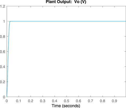
FIGURE 13. Plant output using MPADRC.

FIGURE 14. Plant inputs.
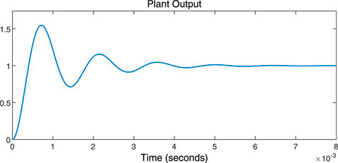
FIGURE 15. Plant output using the ADRC controller only.
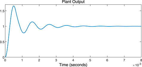
FIGURE 16. Interleaved plant output using the ADRC controller only.
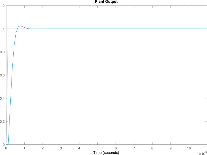
FIGURE 17. Plant output using the MPC controller only.
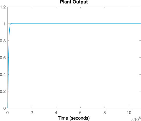
FIGURE 18. Interleaved plant output using the MPC controller only.
6 Conclusion
A novel MPADRC technique that is basically a combination of MPC and ADRC as the outer loop and the inner loop, respectively, is presented for a non-minimum phase behavioral boost converter. Also, its effectiveness is shown with the said techniques individually as used previously. Moreover, the response of interleaving is shown in this article, especially for the two-phase interleaved converter, and one can readily observe the difference between a simple boost converter and an interleaved boost converter. The work motivates the control of DC converters using advanced optimization techniques rather than conventional techniques. Moreover, the future work will include the higher phases of the interleaving technique and also some other converters, that is, buck, SEPIC, and Cuk converters.
Data availability statement
The original contributions presented in the study are included in the article/Supplementary Materials; further inquiries can be directed to the corresponding author.
Author contributions
The main idea, simulation, analysis, and writing of this manuscript were carried out by MS and supervised by YX and TM, KM, and AS carried out literature review, overall layout formatting, and proofreading, while AM and AA provided substantial and intellectual contributions.
Acknowledgments
The Deanship of Scientific Research (DSR) at King Abdulaziz University (KAU), Jeddah, Saudi Arabia has funded this project, under grant no. (KEP-MSc: 122-135-1443), and supported by National Natural Science Foundation of China under Grant 61836001.
Conflict of interest
The authors declare that the research was conducted in the absence of any commercial or financial relationships that could be construed as a potential conflict of interest.
The handling editor SK is currently organizing a research topic with the author KM.
Publisher’s note
All claims expressed in this article are solely those of the authors and do not necessarily represent those of their affiliated organizations, or those of the publisher, the editors, and the reviewers. Any product that may be evaluated in this article, or claim that may be made by its manufacturer, is not guaranteed or endorsed by the publisher.
References
Ahmed, A., Nasim, U., Youcef, B., Abdulrahman, B., Hend, A., and Asier, I. (2022). Expert knowledge based proportional resonant controller for three phase inverter under abnormal grid conditions. Int. J. Green Energy 2022, 1–17. doi:10.1080/15435075.2022.2107395
Anang, S. H., and Leksono, E. (2016). “Model predictive control design and performance analysis of a pasteurization process plant,” in Proceedings of International Conference on Instrumentation, Control and Automation (ICA), Bandung, Indonesia, 81–87.
Belda, K., and Vosmik, D. (2016). Explicit generalized predictive control of speed and position of PMSM drives. IEEE Trans. Ind. Electron. 63 (6), 3889–3896. doi:10.1109/tie.2016.2515061
Bemporad, A., Morari, M., Dua, V., and Pistikopoulos, E. N. (2002). The explicit linear quadratic regulator for constrained systems. Automatica 38 (1), 3–20. doi:10.1016/s0005-1098(01)00174-1
Chen, W. H., Yang, K., Guo, L., and Li, S. (2016). Disturbance-observer-based control and related methods-an overview. IEEE Trans. Ind. Electron. 63 (2), 1083–1095. doi:10.1109/tie.2015.2478397
Feng, H., and Guo, B. Z. (2017). Active disturbance rejection control: Old and new results. Annu. Rev. Control 44, 238–248. doi:10.1016/j.arcontrol.2017.05.003
Forouzesh, M., Siwakoti, Y. P., Gorji, S. A., Blaabjerg, F., and Lehman, B. (2017). Step-up DC–DC converters: A comprehensive review of voltage boosting techniques, topologies, and applications. IEEE Trans. Power Electron. 32 (12), 9143–9178. doi:10.1109/tpel.2017.2652318
Gustavo, A. L. H., Silva, R. N. A. L., Praca Luiz, P. P., Barreto, H. S. C., and Oliveira, D. S. (2010). Interleaved boost converter with high voltage gain. IEEE Trans. Power Electron. 25 (11), 2753–2761. doi:10.1109/tpel.2010.2049379
Han, J. (2009). From PID to active disturbance rejection control. IEEE Trans. Ind. Electron. 56 (3), 900–906. doi:10.1109/tie.2008.2011621
Han, J. (1999). Nonlinear design methods for control systems. IFAC Proc. Vol. 32 (2), 1531–1536. doi:10.1016/s1474-6670(17)56259-x
Huang, Y., and Xue, W. (2014). Active disturbance rejection control: Methodology and theoretical analysis. ISA Trans. 53 (4), 963–976. doi:10.1016/j.isatra.2014.03.003
Judewicz, M. G., Gonzalez, S. A., Echeverria, N. I., Fischer, J. R., and Carrica, D. O. (2016). Generalized predictive current control (GPCC) for grid-tie three-phase inverters. IEEE Trans. Ind. Electron. 63 (7), 4475–4484. doi:10.1109/tie.2015.2508934
Karamanakos, P., Geyer, T., Oikonomou, N., Kieferndorf, F. D., and Manias, S. (2014). Direct model predictive control: A review of strategies that achieve long prediction intervals for power electronics. EEE. Ind. Electron. Mag. 8 (1), 32–43. doi:10.1109/mie.2013.2290474
Khan, S. A., Ansari, J. A., Chandio, R. H., Munir, H. M., Alharbi, M., and Alkuhayli, A. (2022). AI based controller optimization for VSC-MTDC grids. Front. Energy Res. 10, 1008099. doi:10.3389/fenrg.2022.1008099
Kim, S. K., Park, C. R., Kim, J. S., and Lee, Y. I. (2014). A stabilizing model predictive controller for voltage regulation of a DC/DC boost converter. IEEE Trans. Control Syst. Technol. 22, 2016–2023. doi:10.1109/tcst.2013.2296508
Kosai, H., McNeal, S., Jordan, B., Scofield, J., Ray, B., and Turgut, Z. (2009). Coupled inductor characterization for a high performance interleaved boost converter. IEEE Trans. Magn. 45, 4812–4815. doi:10.1109/tmag.2009.2024639
Lee, P. W., Lee, Y. S., Cheng, D. K. W., and Liu, X. C. (2000). Steady state analysis of an interleaved boost converter with coupled inductors. IEEE Trans. Ind. Electron. 47 (4), 787–795. doi:10.1109/41.857959
Li, P., Liu, R., and Ma, X. (2017). “Adaptive indirect model predictive control schemes for boost converters,” in 36th Chinese Control Conference (CCC), 26-28 July 2017 (Dalian, China: IEEE), 9203–9207.
Li, P., Ruiyu, L., Tianying, S., Jingrui, Z., and Zheng, F. (2018). Composite adaptive model predictive control for DC-DC boost converters. IET Power Electron. 11 (10), 1706–1717. doi:10.1049/iet-pel.2017.0835
Madoński, R., and Herman, P. (2015). Survey on methods of increasing the efficiency of extended state disturbance observers. ISA Trans. 134, 18–27. doi:10.1016/j.isatra.2014.11.008
Mayne, D. Q. (2014). Model predictive control: Recent developments and future promise. Automatica 50 (12), 2967–2986. doi:10.1016/j.automatica.2014.10.128
Murali, N., Shriram, K. V., and Muthukumar, S. (2010). Model predictive control of boost converter with RLE load. Int. J. Comput. Appl. 11 (3), 0975–8887.
Nassima, O., Lehouche, H., Youcef, B., and Achour, A. (2021). Indoor temperature regulation and energy consumption inside a working office in building system using a predictive functional control. Energy Sources, Part A Recovery, Util. Environ. Eff. doi:10.1080/15567036.2021.2017517
Omar, H., Van Mierlo, J., and Lataire, P. (2012). Analysis, modeling, and implementation of a multidevice interleaved DC/DC converter for fuel cell hybrid electric vehicles. IEEE Trans. Power Electron. 27 (11), 4445. doi:10.1109/TPEL.2012.2183148
Raziei, S. A., and Jiang, Z. (2016). “Model predictive control for complex dynamic systems,” in Proceedings of IEEE National Aerospace and Electronics Conference (NAECON) and Ohio Innovation Summit (OIS), Dayton, USA, 193–200.
Saif, A., and Ahmad, A. (2019). Active disturbance rejection control of DC–DC boost converter: A review with modifications for improved performance. IET Power Electron. 12 (8), 2095–2107. doi:10.1049/iet-pel.2018.5767
Vazquez, S., Leon, J., Franquelo, L. G., Rodriguez, J., Young, H. A., Marquez, A., et al. (2014). Model predictive control: Areview of its applications in power electronics. EEE. Ind. Electron. Mag. 8 (1), 16–31. doi:10.1109/mie.2013.2290138
Wang, L. (2009). Model predictive control system design and implementation using MATLAB. Berlin, Germany: Springer.
Yao, K., Tang, W., Xiaopeng, B. I., and Lyu, J. (2016). ‘An online monitoring scheme of DC-link capacitor’s ESR and C for a boost PFC converter. IEEE Trans. Power Electron. 29 (7), 5944–5951. doi:10.1109/tpel.2015.2496267
Zhao, H., Wu, Q., Wang, J., Liu, Z., Shahidehpour, M., and Xue, Y. (2017). Combined active and reactive power control of wind farms based on model predictive control. IEEE Trans. Energy Convers. 32, 1177. doi:10.1109/TEC.2017.2654271
Zheng, Q., Gao, L. Q., and Gao, Z. (2012). On validation of extended state observer through analysis and experimentation. J. Dyn. Syst. Meas. Control 134 (2), 024505. doi:10.1115/1.4005364
Keywords: boost converter, interleaved boost converter, model predictive control (MPC), active disturbance rejection control (ADRC), MPADRC
Citation: Samad MA, Xia Y, Manzoor T, Mehmood K, Saleem A, Milyani AH and Azhari AA (2023) Composite model predictive control for the boost converter and two-phase interleaved boost converter. Front. Energy Res. 10:1009812. doi: 10.3389/fenrg.2022.1009812
Received: 02 August 2022; Accepted: 21 October 2022;
Published: 16 January 2023.
Edited by:
Salah Kamel, Aswan University, EgyptReviewed by:
Youcef Belkhier, Maynooth University, IrelandMuhammad Asad, Dalhousie University, Canada
Copyright © 2023 Samad, Xia, Manzoor, Mehmood, Saleem, Milyani and Azhari. This is an open-access article distributed under the terms of the Creative Commons Attribution License (CC BY). The use, distribution or reproduction in other forums is permitted, provided the original author(s) and the copyright owner(s) are credited and that the original publication in this journal is cited, in accordance with accepted academic practice. No use, distribution or reproduction is permitted which does not comply with these terms.
*Correspondence: Yuanqing Xia, eGlhX3l1YW5xaW5nQGJpdC5lZHUuY24=