 Hongda Hao
 Jirui Hou2*
95% of researchers rate our articles as excellent or good
Learn more about the work of our research integrity team to safeguard the quality of each article we publish.
Find out more
ORIGINAL RESEARCH article
Front. Energy Res. , 24 January 2023
Sec. Advanced Clean Fuel Technologies
Volume 10 - 2022 | https://doi.org/10.3389/fenrg.2022.1002053
This article is part of the Research Topic The Challenge and Opportunity of CCUS in the Development of Unconventional Resource View all 15 articles
A well-to-well interplay of CO2 huff-n-puff is proposed as a novel gas injection strategy for displacing interwell-remaining oil in a well pair in an inclined oil reservoir. The well-to-well interplay mechanisms for enhanced oil recovery (EOR) are first studied in the laboratory using a three-dimensional (3D) physical model. Different CO2 injection schemes are designed according to different well locations, and the production performance including oil, water, and gas rates is used for the EOR evaluation. A sensitivity analysis of the well-to-well interplay is then studied using a numerical model, and geological, developmental and fluidic factors are considered in the simulations. The experimental results show that, when CO2 is injected into a lower well, a higher well always benefits with an oil increment. Under the effects of gravity segregation and edge-water driving, the injected CO2 at the lower position can move upward to a higher position, where a large proportion of crude oil remains between wells after natural edge-water flooding. Oil recovery from the well-to-well interplay is 2.30% higher than conventional CO2 huff-n-puff in the laboratory. Numerical results show that CO2 injection mass, stratigraphic dip, horizontal permeability, and interwell spacing are the factors that most influence the well-to-well interplay; an application criterion for the well-to-well interplay is then proposed based on the simulations. Pilot tests using the well-to-well interplay of CO2 huff-n-puff have been widely applied in C2-1 Block, Jidong Oilfield, China, since 2010. A total of 2.27 × 10⁴ m3 crude oil was recovered to the end of 2018, and the oil/CO2 exchange ratio was as high as 3.92. The well-to-well interplay not only effectively extracted the interwell-remaining oil but also achieved higher CO2 utilization efficiency. The findings of this study can lead to a better understanding of the EOR mechanisms used in the well-to-well interplay during the CO2 huff-n-puff process in an inclined oil reservoir.
Given the continuous consumption of conventional reservoir reserves, unconventional resources have been of wide interest in recent years. Heavy oil reservoirs as one unconventional resource face challenges in oil production due to low oil mobility within the porous media (Babadagli, 2003; Huang et al., 2019; Shilov et al., 2019). Thermal methods, including steam injection and in situ combustion, are the most widely used techniques for enhanced heavy oil recovery; however, their applications are limited in thin or deep layers because of massive heat loss and the high investment necessary (Wang et al., 2018; Alajmi, 2021). Solvent-based non-thermal methods, including cyclic solvent injection and vapor extraction, are proving suitable for enhanced oil recovery (EOR) in these kinds of reservoirs (Jiang et al., 2014; Ma et al., 2017). Among such methods, the CO2 huff-n-puff process is considered a promising technique for these complicated oil reserves (Ahadi & Torabi, 2018; Zhou et al., 2019). When CO2 is injected into heavy oil reservoirs, the main EOR mechanisms include viscosity reduction, oil swelling, IFT reduction, and light/medium components extraction, greatly enhancing heavy oil production during the CO2 huff-n-puff process (Kavousi et al., 2014; Cui et al., 2017; Li et al., 2018; Kashkooli et al., 2022; Zhou et al., 2022).
C2-1 Block in the Jidong Oilfield, China, is a heavy oil reservoir with a viscosity of 289 mPa·s under formation conditions (60, 16.24 MPa); it is an inclined reservoir with a stratigraphic dip of 15° (Figure 1). The block was initially developed by natural edge-water flooding from 2003, obtaining oil recovery of 4.79% by the end of 2010. During this operation, several wells faced severe water channeling problems, with water-cut values as high as 99%, and little oil was recovered. Several CO2 huff-n-puff processes were conducted to enhance this oil recovery between 2008 and 2010. After CO2 was injected into a single well, the oil production rate was enhanced from less than 2 t/d to more than 10 t/d, and the water cut also dropped to as low as 20–30%. Although the oil increases were obtained with a CO2 injection, they sharply dropped to small values for the second cycle of CO2 huff-n-puff—as observed by Ma et al. (2015). Furthermore, since CO2 huff-n-puff is just a stimulation method for single wells with a limited range (Li et al., 2017), it can only extract the oil near the wellbore area: a quantity of crude oil still remained between the wells after CO2 huff-n-puff in the C2-1 Block. Although a variety of chemicals including viscosity reducer, foaming agent, and gel have been proposed to further enhance CO2 huff-n-puff oil recovery (Hao et al., 2021; Hao et al., 2022; Qu et al., 2022), they are still single-well stimulation methods, and novel techniques or gas injection strategies need to be studied to extract interwell-remaining oil during the CO2 huff-n-puff process.
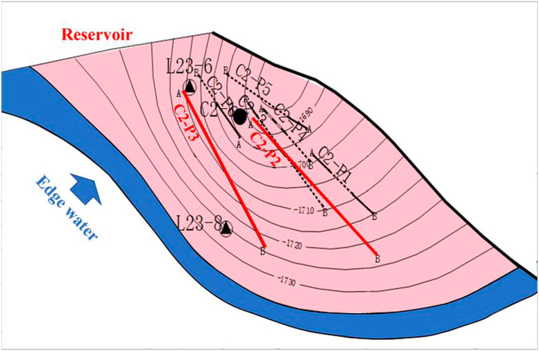
FIGURE 1. Top structure map of C2-1 Block, Jidong Oilfield, China.
When gas and water are injected into a formation, the gas will move to the top of the reservoir while the water will move to the bottom due to gravity—this is called “gravity segregation”. In a horizontal reservoir, gravity segregation is usually a negative factor since the injected gas and water will override the oil (Fayers & Zhou, 1996). For example, the water-alternating-gas (WAG) technique is considered the most useful for EOR when CO2 is mixed with oil; however, the gas–oil mixture will be separated by gravity as the mixture moves further away from the injector. As a result, the WAG process provides an unsatisfactory sweep efficiency with gravity segregation, leading to an early gas breakthrough in the producer (Afzali et al., 2018; Khan & Mandal, 2020). The gas-assisted gravity drainage (GAGD) technique has recently been proposed as an effective EOR method because it takes full advantage of gravity segregation, and a higher formation dip is favorable for its EOR (Chen et al., 2021). During a GAGD process, the oil is usually driven by CO2 down-dip from the pores toward the wells. With a properly designed gas injection strategy, the gas breakthrough can be significantly delayed, with recovery of more than 30% in the laboratory (Rezk et al., 2019; Al-Obaidi et al., 2022).
Although, GAGD could achieve remarkable oil recovery in the inclined oil reservoirs, most GAGD processes are operated in a model without edge water. In the presence of an active aquifer, conditions could be completely different because the water coning could severely affect EOR. The treatment of edge water should be considered a primary task when applying an EOR method to this kind of reservoir. CO2 has proven to be an effective method for water treatment (Wang et al., 2021; Tian et al., 2022); when it is injected into a lower location in an inclined oil reservoir, it will first delay the edge-water coning. Then, the CO2 will move upward with the assistance of edge-water driving and gravity segregation, where the oil remaining between a well pair is just right at the higher position. As a result, a well-to-well interplay will occur with the interwell-remaining oil produced from the higher position. Gravity segregation is typically affected by developmental, geological, and fluidic factors. For example, Stone (1982) observed that the injection rate, vertical permeability, and density difference between water and gas are the main parameters that affect gravity segregation. The study conducted by Rogers & Grigg (2001) revealed that the increase in the vertical-to-horizontal permeability ratio (Kv/Kh) will reduce oil recovery during the WAG process, due to the dominant effect of gravity segregation. Al-Mudhafar et al. (2018) believe that reservoir heterogeneity is the most crucial factor that strongly affects hydrocarbon recovery during GAGD. Thus, as a CO2–EOR method governed by gravity segregation, the influencing factors of well-to-well interplay during the CO2 huff-n-puff process proposed in this paper should also be studied to achieve a better CO2–EOR effect.
In order to study the mechanisms of interwell-remaining oil displacement using a well-to-well interplay of CO2 huff-n-puff in an inclined oil reservoir, a well pair was established in a three dimensional (3D) inclined physical model. CO2 was injected into the model through the lower well only, the higher well only, and the lower and higher wells simultaneously. The production performances, including oil, water, and gas rates, were used to evaluate the interplay mechanisms between the wells. A sensitivity analysis of the well-to-well interplay was then studied using a base reservoir model, and geological, developmental, and fluidic factors including CO2 injection mass, interwell spacing, stratigraphic dip, horizontal and vertical permeability, and oil viscosity were considered in the simulations. EOR tests using the well-to-well interplay of CO2 huff-n-puff were conducted in the pilot, and the oil recovered by the well-to-well interplay is also introduced in this paper.
Theoretical analysis, physical experiments, numerical simulation, and field tests were utilized to study the EOR mechanisms, influencing factors, and its application to the well-to-well interplay of CO2 huff-n-puff; the technical route of this study is shown in Figure 2.
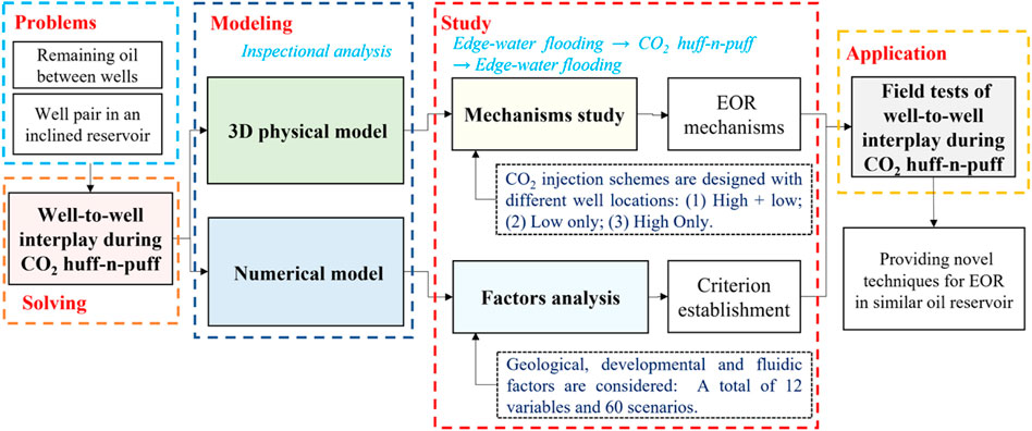
FIGURE 2. Technical route and major steps used in the study of well-to-well interplay of CO2 huff-n-puff.
The inclined oil reservoir of C2-1 Block is in a geological reserve of 4.51 × 10⁵ m3. The average porosity and permeability of the reservoir is 25.9%, 667 × 10−3 μm2, respectively, the depth of water/oil contact (WOC) is 1735 m, and the aquifer size is 100 times that of the oil reservoir. Since the purpose of this paper is mainly to discover the well-to-well interplay mechanisms and its influencing factors, the actual oil reservoir was simplified to an equivalent model with an effective radius of 316.23 m and an effective thickness of 26.8 m; Wells C2-P3 and C2-P2 were selected to form a typical well pair. The basic parameters of the equivalent model were the same as the actual oil reservoir (Table 1).
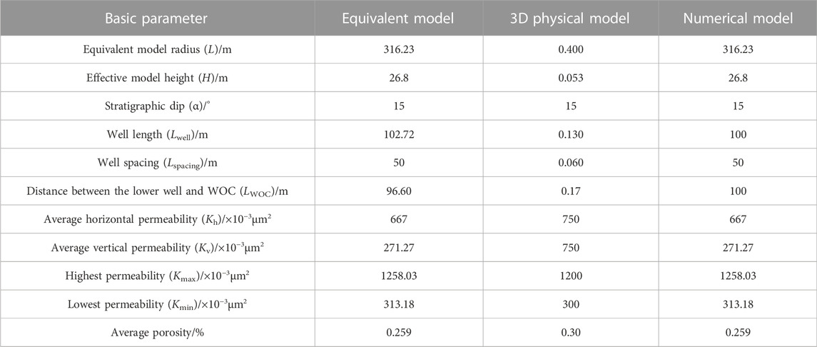
TABLE 1. Basic parameters for the equivalent reservoir, physical model, and numerical model.
Scaling groups of the geometrical parameters derived by Shook et al. (1992) were then used to establish the 3D physical and numerical models, which were proven to be an effective method for CO2–EOR by Li et al. (2015) and Zhao et al. (2018). An aspect ratio of the model (Rmodel) was used to ensure the similarity of the model; aspect ratios of well-length and spacing (Rwell and Rspacing) and an aspect ratio of WOC (RWOC) were used to ensure the similarity of the well pair. The permeability ratio (Kmn) was used to simulate a heterogeneity similar to the reservoir. Since the basic parameters of the equivalent model are given, the dimensionless group values were calculated (Table 2). Thence, the unknown parameters of the physical and numerical models were determined with the dimensionless values, with the final results listed in Table 1.
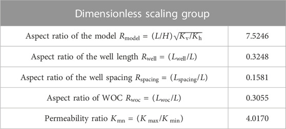
TABLE 2. Dimensionless group values calculated from the equivalent reservoir.
According to the calculations, the 3D physical model used for well-to-well interplay during the CO2 huff-n-puff process had a diameter of 400 mm, a thickness of 53 mm, and a stratigraphic dip of 15° (Figure 3A). The horizontal well pair including P1H and P2H was established in the middle of the core. The lengths of P1H and P2H were both 130 mm, the spacing between P1H and P2H is 65 mm, and the distance between P1H and WOC was 120 mm (Figure 3B). The model was a heterogeneous core with an average permeability of 750 × 10−3 μm2, upper layer permeability of 300 × 10−3 μm2, and bottom layer permeability of 1200 × 10−3 μm2. In order to achieve the different permeabilities of the upper and lower layers, 1D homogenous cores were first fabricated with different mesh ranges of sand in the laboratory Figure 3C). The proportions of different sands were determined after the permeability tests of 1D cores, with the results listed in Table 3. The sand formulas were then used to fabricate the 3D physical model (Figure 3D).
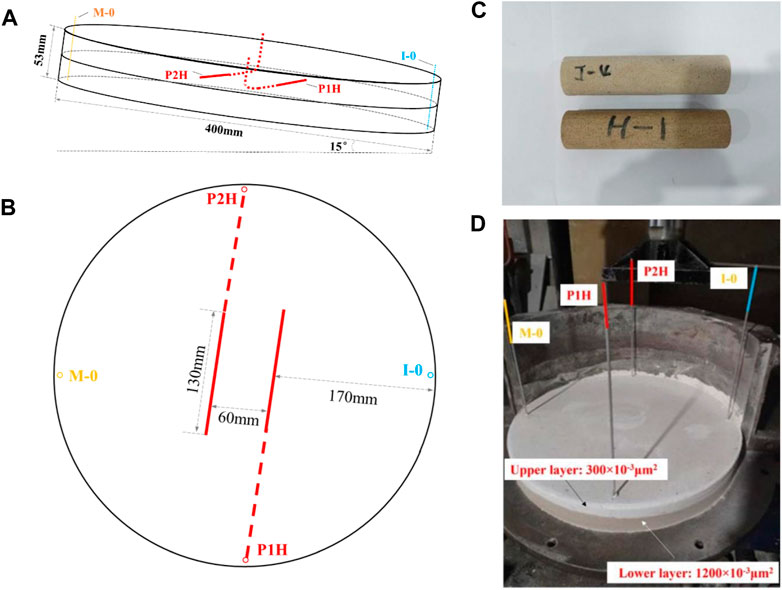
FIGURE 3. 3D physical model used for the well-to-well interplay of CO2 huff-n-puff. (A) Side view and (B) top view of the designed model. (C) Picture of the 1D core. (D) Picture of the 3D core.
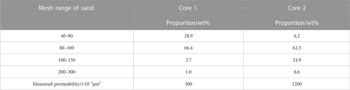
TABLE 3. Sand formula used to fabricate different permeabilities for 3D cores (measured from 1D cores).
The numerical model was designed to be 500 m × 200 m × 30 m using a CMG-GEM simulator, and the value of the net gross ratio (NTG) was set at 0.9. With the same effective thickness of 26.8 m, the effective radius (L) was equal to 316.23 m in a circular equivalent model (Table 1). A Cartesian grid was used in the modeling—51 grids with a length of 9.8039 m were set in the x direction, 41 grids with a length of 4.8780 m were set in the y direction, and 15 grids with a length of 2 m were set in the z direction. The reservoir dip was set at 15°, and the depth of WOC was 1735 m. The sand body was normal rhythmic with an average permeability of 667 × 10−3 μm2 and an average porosity of 25.9%. The initial oil saturation was set as 0.65, and the geological reserve was calculated to be same as the reserve in the real reservoir. An edge-water aquifer was connected to the bottom of the reservoir, which was 100-times the model size. P1H and P2H with the same horizontal length of 100 m were set as the lower and the higher wells, respectively. The spacing between P1H and P2H was set at 50 m, and the distance between P1H and WOC was set at 100 m. The grid top of the numerical model is shown in Figure 4.
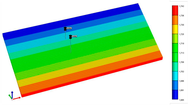
FIGURE 4. Numerical model used for the well-to-well interplay during CO2 huff-n-puff (grid top).
The oil and water samples used for the 3D physical experiments were collected from the block. The density of the formation oil was 0.97 × 10³ kg/m3, the viscosity was 289 mPa·s, and the gas/oil ratio was 18.9 m3/m3 under formation conditions (60°C, 16.24 MPa). The salinity of the formation water was 2.83 × 10³ mg/L, and the injected CO2 with a purity of 99.99 mol% was from Beijing, China. The basic parameters of the 3D physical models are listed in Table 4. The experimental setup consisted of six sub-systems: an injection system, an edge-water system, a displacement system, a production system, a temperature control system, and a data-acquisition system. In the injection system, the formation water, formation oil, and CO2 were stored in cylinders and then injected into the model by a pump. In the edge-water system, formation water was stored in the cylinder and then injected into the model through Well I-0 (Figure 3). The 3D physical model was placed in the coreholder with a dip of 15°. In the production system, backpressure regulars (BPRs) were connected to the horizontal wells to control the production pressure. The produced oil and water were recorded by test tubes, while the gas was measured by using a gas flow meter. The thermostat was used to maintain the reservoir temperature, and the pressure monitored by M-0 was obtained by the data-acquisition system.
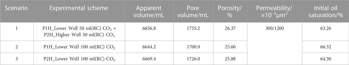
TABLE 4. Basic parameters of 3D physical models.
Several 3D experiments were designed in the laboratory to study the well-to-well interplay mechanisms of CO2 huff-n-puff. The models were first displaced by the edge water and then by the CO2 huff-n-puff process. Different injection schemes were designed with different injection wells and CO2 volume allocations (Table 4). The bulk volume of the core was first measured before the 3D experiment. The core was then evacuated and saturated with formation water. The porosity was determined as the ratio of water saturation volume to bulk volume. The core was then displaced by formation oil to reach an initial oil saturation—calculated as the ratio of produced oil volume to the pore volume.
Edge-water driving was conducted first in the model according to these detailed procedures: 1) The formation temperature was set to 60°C, and the production pressures of the horizontal wells (P1H and P2H) were set to 16.40 MPa using BPRs. 2) Water was then injected through I-0 under a constant rate of 0.4 Ml/min to simulate the natural edge-water driving. 3) P1H and P2H were opened for production and then shut in simultaneously when the composite water cut of the well pair reached 98%.
CO2 huff-n-puff was then conducted after edge-water driving. In Scenario 1, CO2 was injected into the model through both the lower well P1H and the higher well P2H. The detailed procedures were 1) 50 Ml (reservoir conditions, RC) CO2 and 50 Ml (RC) CO2 were injected through P1H and P2H, individually, and then, these wells were shut in. 2) After a soaking time of 12 h, P1H and P2H were re-opened again for production. Simultaneously, the edge water was re-injected into the model through I-0. 3) The experiment was terminated when the composite water cut again reached 98%. The pressure, oil production, water production, and gas production were measured, and the oil recovery enhanced by CO2 huff-n-puff was then calculated.
Scenarios 2 and 3 were designed with an equal total CO2 volume of 100 Ml (RC) but different injection wells and gas allocations. In Scenario 2, 100 Ml of CO2 was injected into the model only through the lower well P1H. In Scenario 3, 100 Ml of CO2 was injected into the model only through the higher well P2H. Other procedures were the same as mentioned previously. After the experiments were finished, the production performances of the three scenarios were compared to study the interplay mechanisms during the CO2 huff-n-puff process.
A sensitivity analysis of well-to-well interplay during CO2 huff-n-puff was then conducted using the numerical model shown in Figure 4. Seven pseudo-components—CO2, C1+N2, C2∼C4, C5∼C6, C7+, C11+, and C28+—were set to simulate the formation oil, with proportions of 0%, 0%, 1.65%, 5.69%, 18.24%, 29.93%, and 44.49%, respectively. The viscosity of formation oil was tested at 289.25 mPa·s with a density of 0.974 × 10³ kg/m3—similar to the real oil sample under formation conditions. Figure 5 shows the oil–water and oil–gas relative permeabilities used for the numerical simulation.
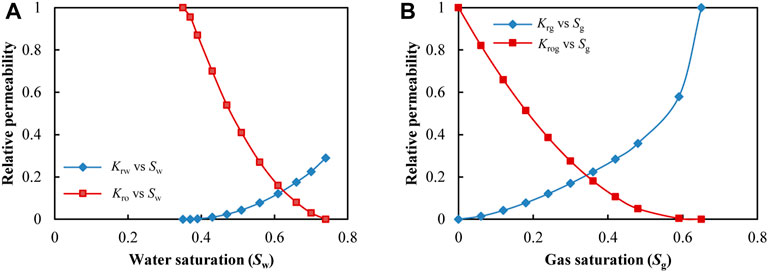
FIGURE 5. Relative permeability used for the numerical simulation. (A) Oil–water relative permeability. (B) Oil–gas relative permeability.
As with the laboratory experiments, natural edge-water flooding was first conducted in the numerical model, and the liquid production rates of P1H and P2H were set equally at 18.42 m3/d. Figure 6 gives the fitting curves of the daily production oil rates obtained from C2-P2 in the real reservoir and P2H in the numerical model. The daily oil rate was more than 16 m3/d at the initial production stage (less than 18 days), dropping sharply to about 8 m3/d within 50 days, and then gradually dropping to about 1 m3/d. The average oil rate was 4.06 m3/d within 500 days in the numerical model—similar to the average rate of 4.08 m3/d obtained from C2-P2. Thus, the built model can be used to reflect the production performances of the real reservoir. The edge-water flooding process was conducted until the composite water-cut of the well pair reached 98%. Then, the CO2 huff-n-puff process was conducted with CO2 injected only through the lower well P1H. A total CO2 mass of 400t was injected at a rate of 100 t/d. After 30 days of soaking time, P1H and P2H were reproduced until the composite water cut of the well pair again reached 98%. The oil production of the well pair enhanced by well-to-well interplay was obtained after the simulation.

FIGURE 6. Fitting curves of daily oil rates obtained from the real reservoir and numerical model.
Sensitivity analysis was then conducted, considering the developmental, geological, and fluidic factors used in the base model. A total of 12 variables and 60 scenarios were designed using the base model (as listed in Table 5). The oil production recovered by CO2 puff-n-huff (ΔQo) was used to evaluate the well-to-well interplay for the well pair. Since five values were set for each variable, several values of ΔQo can be obtained after the simulations, and then, an average oil production (
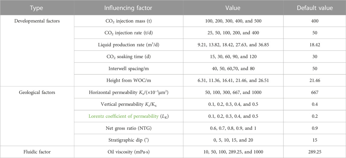
TABLE 5. Sensitivity analysis designed for the well-to-well interplay of CO2 huff-n-puff.
Before the CO2 huff-n-puff operations, edge-water driving experiments were first conducted in the 3D physical models to form a similar remaining oil saturation; the results are compared in Table 6. Since the lower well P1H was closer to the edge water, the oil recovery of P1H was always the lowest with 6.84%–8.07%. The higher well P2H obtained a higher oil recovery of 11.21%–13.69%. When the composite water-cut of the well pair reached 98%, the total injection volume of edge water was around 1.70–1.80 PV, and the total oil recovery for the well pair was 18.05%–21.76%.
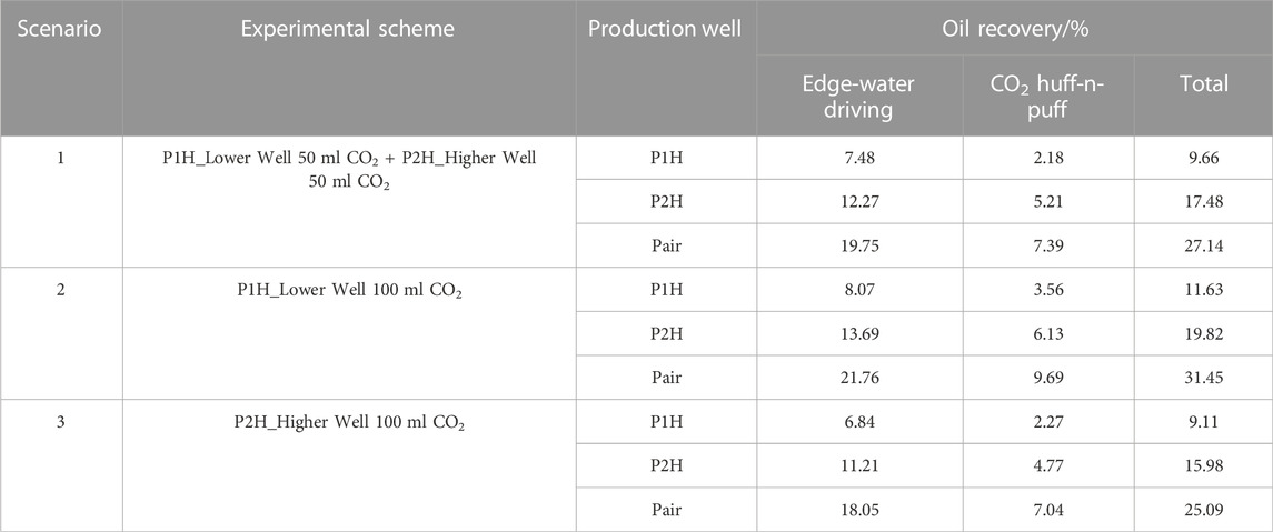
TABLE 6. Experimental results of CO2 huff-n-puff conducted in 3D physical models.
In order to study the mechanisms of well-to-well interplay during the CO2 huff-n-puff process, different CO2 injection schemes were designed according to the wells’ locations. For the conventional CO2 huff-n-puff conducted in Scenario 1, a total oil recovery of 7.39% was obtained for the well pair. The lower well P1H obtained an oil recovery of 2.18%, and the higher well P2H obtained an oil recovery of 5.21%. However, when CO2 was injected only through the lower well P1H (Scenario 2), the highest oil recovery was achieved among the three scenarios. Not only did the operation well P1H obtain an oil recovery of 3.56%, but the higher well P2H also obtained an oil recovery of 6.13%., indicating an interplay between P1H and P2H during the CO2 huff-n-puff process. When CO2 was injected only through the higher well P2H (Scenario 3), the lowest oil recovery was obtained, with only 2.27% oil recovery obtained from P1H and 4.77% oil recovery from P2H.
Figure 7 compares the composite water cuts for different CO2 huff-n-puff scenarios. At the initial production stage of CO2 huff-n-puff, it can be observed that the lowest water-cut drop was obtained when CO2 was injected only through lower well P1H (Scenario 2). CO2 is soluble in the water phase, which is beneficial for treatment through water invasion. After comparing Scenarios 1 and 2, it is evident that a larger volume of CO2 injected into the lower well allows better edge-water control. In addition to the lowest water-cut drop, production life can also be prolonged to 0.58 PV when the water cut again reaches 98% in Scenario 2. It can be observed that a secondary water cut drop formed in the successive production stage in Scenarios 1 and 2. Since CO2 was injected though the lower well, it could be soluble in the remaining oil between P1H and P2H. With the assistance of edge-water driving, the dissolved CO2 was displaced to a higher position, which then brought the amount of interwell-remaining oil to the higher well P2H. When CO2 was injected only through the higher well P2H (Scenario 3), the water cut drop was mainly due to the oil recovered from P2H. Since no gas was injected through the lower well, the edge-water invasion was severe with the shortest production life of only 0.25 PV, and the water cut increased sharply with no period of secondary water-cut drops.
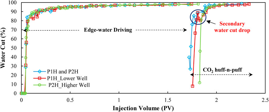
FIGURE 7. Comparison of composite water cuts for different CO2 huff-n-puff scenarios.
Figure 8A shows the water cut curves of individual wells in Scenario 2. When the composite water cut reached 98.27%, the water cut of P1H and P2H was 98.54% and 98.10%, respectively. After CO2 was injected into the lower well P1H, the invasive edge water was treated first by CO2, with the water cut of P1H and P2H dropping to as low as 4.73% and 10.80%, respectively. A large amount of crude oil was produced from P1H and P2H as long as CO2 was produced—revealing it as the main contributor to the oil recovery increase. As the production process continued, the water cut of the lower well P1H increased gradually to around 90%; however, a secondary water cut drop was observed in the higher well P2H. The water cut of P2H again dropped from 91.55% to 62.26% during an injection volume of 1.81 PV to 1.83 PV, which can be attributed to the interwell-remaining oil displaced by the dissolved CO2 and edge water. The injected CO2 not only extracted the oil remaining around P1H and P2H but also displaced the oil remaining between P1H and P2H. Consequently, the oil recovery of the well pair can be maximized by injecting CO2 into the lower position of the model.
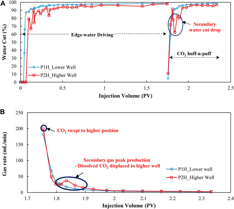
FIGURE 8. Production performance for single wells in Scenario 2 with CO2 injected only through the lower well P2H. (A) Water cut curves. (B) Gas rate curves.
Figure 8B provides the gas production rates for individual wells during the CO2 huff-n-puff process in Scenario 2. Since CO2 was injected only through the lower well P1H, an amount of CO2 was produced from P1H immediately when the well was opened for production. However, it is interested to note that a larger amount of gas was also immediately produced from the higher well P2H. Since the model had a dip of 15°, part of the injected CO2 in the lower position could migrate upward under gravitational differentiation, and then sweep the near-wellbore area of P2H. The remaining oil around P2H could be effectively extracted by the migrated CO2, which then caused a remarkable water drop and oil increase for P2H. As the production process continued, the gas rate of the lower well P1H decreased gradually; however, another peak appeared on the gas rate of the higher well P2H. Since the edge water was being continuously injected into the model, part of the CO2 in the lower position was displaced into the interwell area and then dissolved with the remaining oil. The remaining oil, dissolved CO2, and invasive edge water were then produced successively from the higher well P2H. The duration of the secondary gas production peak for P2H was the same as that of the secondary water cut drop (as shown in Figure 8A), confirming that the oil increase in this period was due to the interwell remaining oil being displaced by CO2 and edge water.
In summary, when CO2 huff-n-puff is conducted in a well pair located in an inclined reservoir, an interplay can be formed between wells with a CO2 injection into the lower position. Not only can water drop and oil increase be obtained from the lower well after the gas injection but also a more remarkable water drop and oil increase can also be obtained from the higher well. On one hand, the injected CO2 in the lower position can migrate upward under gravitational differentiation in the inclined reservoir. On the other hand, dissolved CO2 can be displaced into the interwell area with the assistance of edge-water flooding. Under the influence of migrated CO2, dissolved CO2, and edge water, the oil remaining between the wells can be effectively extracted through the higher well. The oil recovery of the well pair enhanced by CO2 conducted in Scenario 2 is 2.3% better than the conventional CO2 huff-n-huff, indicating that using the well-to-well interplay during a CO2 huff-n-puff process for enhanced oil recovery is a promising gas injection strategy for the inclined oil reservoir.
Although the formation mechanisms of well-to-well interplay during the CO2 huff-n-puff process were revealed using laboratory experiments, the influencing factors still need to be discussed before enlarging its application in field tests. A base reservoir model was built using a CMG-GEM simulator. As in the laboratory experiments, natural edge-water flooding was also first conducted in the base model, and CO2 huff-n-puff was then conducted after the composite water cut reached 98%. For the default model, the liquid production rates of P1H and P2H were set at 18.42 m3. CO2 was injected through the lower well P1H at a rate of 100 t/d, a total CO2 volume of 400t, and CO2 soaking time of 30 days. After the composite water cut of the well pair reached 98%, 175.4t of crude oil was recovered from the lower well P1H, while a significant increase of 1197.24t of crude oil was obtained from the higher well P2H, accounting for 87.16% of the total oil increments for the well pair. Figure 9 shows the oil saturation before and after CO2 huff-n-puff. The edge water mainly flowed through the higher permeable layers at the bottom of the reservoir, and an amount of crude oil remained between P1H and P2H. After the CO2 huff-n-puff process was operated at the well pair, the oil saturation between P1H and P2H dropped notably due to the occurrence of well-to-well interplay. The injected CO2 through the lower well P1H migrated upward with the displacement of edge water; the remaining oil between the wells was then effectively displaced from the higher well P2H. The simulation result was consistent with the experimental result, confirming that the well-to-well interplay of CO2 huff-n-puff is an effective EOR method for the well pair in the inclined oil reservoir.
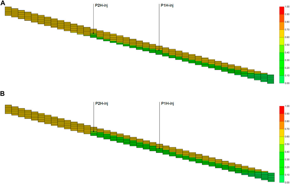
FIGURE 9. Oil saturation before and after the well-to-well interplay of CO2 huff-n-puff. (A) Before and (B) after the well-to-well interplay of CO2 huff-n-puff.
Sensitivity analysis was then conducted using the base model, with the simulation results shown in Table 7 and Figure 10. The calculated coefficient of variation (Cv) ranged from 0.0553 to 0.7287, with an average value of 0.2103. The Cv values of four factors— CO2 injection mass, stratigraphic dip, horizontal permeability (Kx) and interwell spacing—were higher than its average. These four are considered the factors of most influence for the well-to-well interplay during CO2 huff-n-puff. CO2 injection mass is the primary factor in the well-to-well interplay, and Figure 11 shows the production performance of different CO2 injection masses for the well pair. When the mass was less than or equal to 200t, the amount of CO2 was mostly produced through the lower well P1H, with little CO2 migrating up to the higher well P2H (Figure 11B). No interplay occurred between P1H and P2H; thus, the oil increment was less than 200t with the operation of CO2 huff-n-puff. When the injected CO2 mass exceeds 200t, the oil increase increased sharply to more than 1000t, a produced gas rate was observed from the higher well P2H, and the composite water cut also showed a secondary drop during the production stage. Thus, the injection mass of CO2 should be more than 200t in order to enhance oil recovery using the well-to-well interplay.
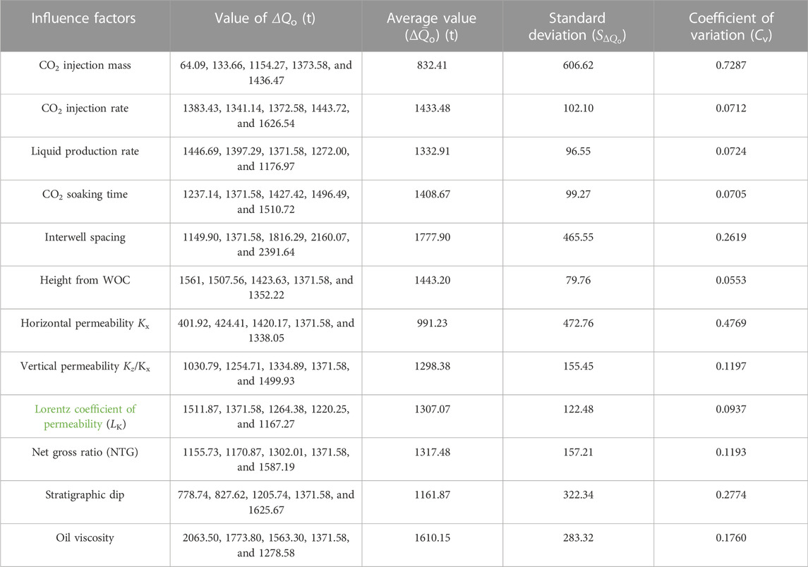
TABLE 7. Simulation results and sensitivity analysis of well-to-well interplay during CO2 huff-n-puff.
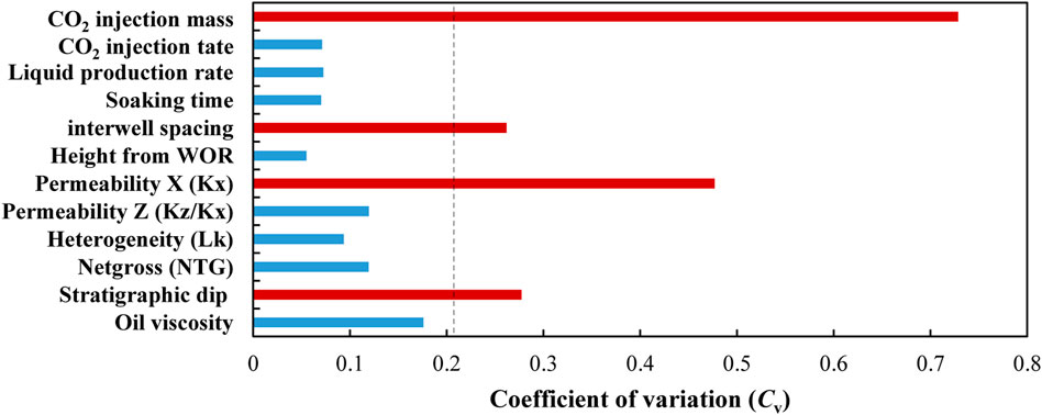
FIGURE 10. Sensitivity analysis results of the well-to-well interplay during the CO2 huff-n-puff process.
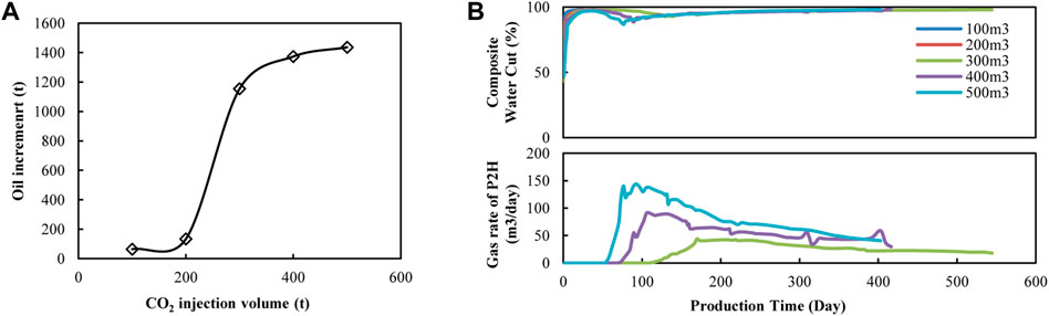
FIGURE 11. Production performance of different CO2 injection volumes for the well-to-well interplay of CO2 huff-n-puff. (A) Oil increment vs. CO2 injection volume. (B) Composite water cut and production gas rate vs. time.
The stratigraphic dip was the secondary influencing factor for the well-to-well interplay, and Figure 12 shows the production performance of different stratigraphic dips during CO2 huff-n-puff. It can be observed that the oil increase is less than 850t when the dip is less than or equal to 5° and that little gas was produced from the higher well P2H. The dip was so small that the injected CO2 could not migrate up to the higher position during one cycle of CO2 huff-n-puff (Figure 12B). When the dip was higher than 5°, the oil increment increased to more than 1000t, a produced gas rate was observed from the higher well P2H, and the composite water cut also showed a secondary drop during the production stage. It can also be observed that a higher stratigraphic dip can recover more oil for the well pair, which is beneficial for the displacement of interwell-remaining oil achieved by CO2 upward migration.
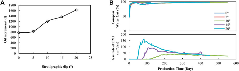
FIGURE 12. Production performance of different stratigraphic dips for well-to-well interplay of CO2 huff-n-puff. (A) Oil increase vs. interwell spacing. (B) Composite water cut and production gas rate vs. time.
Horizontal permeability is the third influencing factor for well-to-well interplay, and Figure 13 shows the production performance of different horizontal permeabilities during CO2 huff-n-puff. It can be observed that the oil increase was less than 500t when the permeability was less than or equal to 100 × 10−3 μm2, and that little gas was produced from the higher well P2H. The permeability was so small that the injected CO2 could not migrate up to the higher position (Figure 13B). When the permeability was higher than 100 × 10−3 μm2, the oil increase increased to more than 1000t, a produced gas rate was observed from the higher well P2H, and the composite water cut also showed a secondary drop during the production stage. Thus, the horizontal permeability should be more than 100 × 10−3 μm2 when using well-to-well interplay for EOR.
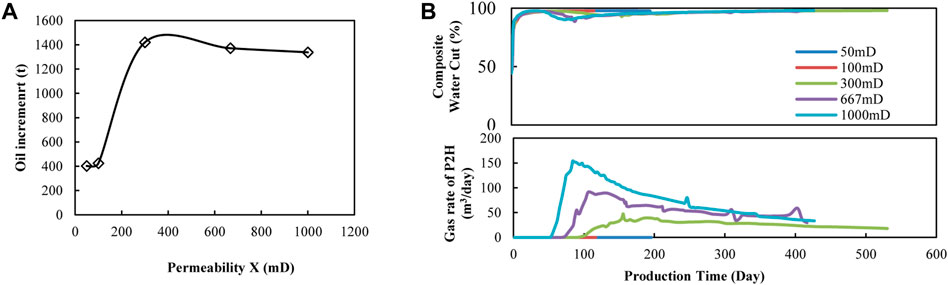
FIGURE 13. Production performance of different horizontal permeabilities for the well-to-well interplay of CO2 huff-n-puff. (A) Oil increase vs. interwell spacing. (B) Composite water cut and production gas rate vs. time.
The interwell spacing is the fourth influencing factor for well-to-well interplay, and Figure 14 shows the production performance of different interwell spacings during CO2 huff-n-puff. It can be observed the oil increase increased as interwell spacing increased, which can be more than 2000t when the spacing exceeds 70 m. As the interwell spacing increased, more crude oil remained between P1H and P2H after edge-water driving. When CO2 was injected into the lower well P1H, oil could be continuously produced from the higher well P2H under CO2 gravitational differentiation and edge-water displacement (Figure 14B). As a result, the composite water cut remained at a level of less than 98% for more than 800 days, and considerable remaining oil was effectively recovered from the reservoir using the well-to-well interplay during CO2 huff-n-puff.
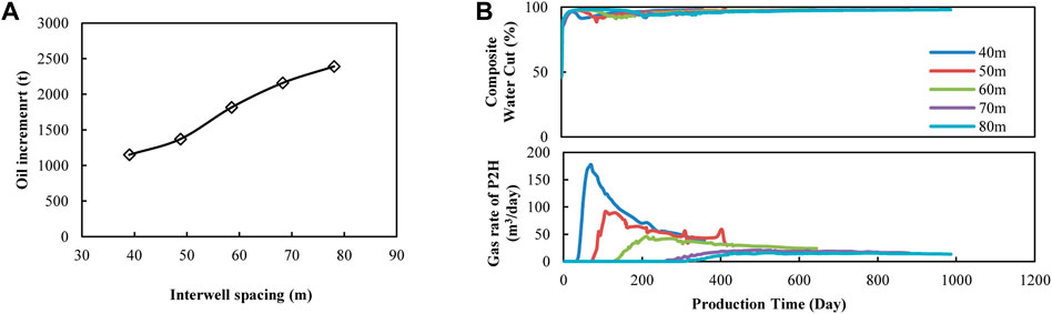
FIGURE 14. Production performance of different interwell spacings for the well-to-well interplay of CO2 huff-n-puff. (A) Oil increase vs. interwell spacing. (B) Composite water cut and production gas rate vs. time.
In summary, a successful CO2-EOR operation using well-to-well interplay mostly depends on both geological and developmental factors. The oil reservoir should be inclined with a stratigraphic dip of more than 5°, and horizontal permeability should be more than 100 × 10−3 μm2. The CO2 injection mass is the primary influencing factor; it should be more than 200t, and CO2 should be injected through the lower position of the reservoir. A larger interwell spacing can allow the injected CO2 to fully dissolve with the crude oil and then displace the remaining oil upward to a higher position. With an elaborate design of gas injection in this inclined oil reservoir, a considerable oil increase of more than 1000t can be recovered using the well-to-well interplay during the CO2 huff-n-puff process.
Pilot tests using well-to-well interplay of CO2 huff-n-puff were widely applied after natural edge-water flooding in C2-1 Block, Jidong Oilfield, China, from 2010; a total of 2.27 × 10⁴ m3 of crude oil was recovered until the end of 2018. Figure 15 shows five typical well pairs using well-to-well interplay where CO2 was injected into the reservoir through the lower wells. After the CO2 injection, the same phenomena were observed with the oil recovered from both the lower and higher wells. Moreover, the oil increases of the higher wells were always higher than those of the lower wells, indicating that the interwell-remaining oil had been successfully displaced using the well-to-well interplay of CO2 huff-n-puff.
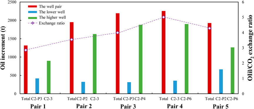
FIGURE 15. Oil increase and oil–CO2 exchange ratio for five well pairs using the well-to-well interplay of CO2 huff-n-puff in pilot tests.
The oil–CO2 exchange ratio is defined as the oil increment enhanced by per unit CO2, which can be used to reflect CO2 utilization efficiency. The higher the value of the oil–CO2 exchange ratio, the more efficient the CO2 utilization is. Figure 15 also shows the total oil increases and the oil–CO2 exchange ratio for these five well pairs. Using well-to-well interplay, the total oil increase for a well pair was more than 1300t during CO2 puff-n-huff; the oil increases for pairs 4 and 5 in particular were more than 2000t. The oil–exchange ratio ranged from 2.85 to 5.01, which means that a small mass of CO2 can recover plenty of crude oil from the reservoir. The total CO2 mass operating in these five pairs was 2460t, the total oil increase was 9642.1t, and the average oil–CO2 exchange ratio was 3.92. The well-to-well interplay not only achieved considerable EOR but also showed great potential for improving the CO2 utilization efficiency during CO2 huff-n-puff.
Although the successful utilization of well-to-well interplay during the CO2 huff-n-puff process has brought great profits to the oil company, there are still some problems to be resolved during its operation. For example, several operations of the well-to-well interplay were failures because of the presence of fractures; however, some were much better than the EOR effects conducted in areas with no fractures. These may lead to completely different EOR mechanisms during the well-to-well interplay, which we will further investigate and report in a future study.
The well-to-well interplay of CO2 huff-n-puff is proposed as a novel gas injection strategy for enhanced oil recovery (EOR) in an inclined oil reservoir. Laboratory experiments, numerical simulations, and pilot tests are reported in this paper, and these are some conclusions:
1) When CO2 is injected into a lower well of a well pair in an inclined oil reservoir, not only can water drop and oil increase be obtained from the lower well, but a more remarkable water drop and oil increase can also be obtained from the higher well. The interplay between wells can dramatically enhance oil recovery for the well pair.
2) The displacement of interwell-remaining oil is the main contribution for EOR using well-to-well interplay. Under gravitational differentiation and edge-water flooding, CO2 and edge water can migrate upward to displace the oil between wells. Physical experimental results show that oil recovery enhanced by a well-to-well interplay is 2.30% higher than recovery using conventional CO2 huff-n-huff.
3) Sensitivity analysis results show that CO2 injection mass, stratigraphic dip, horizontal permeability, and interwell spacing are the factors that most influence well-to-well interplay. To realize a better oil increment, the reservoir dip should be more than 5°, the permeability should be more than 100 × 10−3 μm2, the CO2 injection mass should be more than 300t, and greater interwell spacing is beneficial for achieving a better CO2–EOR effect.
4) A total of 2.27 × 10⁴ m3 of crude oil was recovered using well-to-well interplay in the pilot between 2010 and 2018. The results of five typical well pairs show that the oil–CO2 exchange ratio was as high as 3.92. The well-to-well interplay not only achieved a considerable EOR effect but also showed great potential for improving efficient CO2 utilization during the CO2 huff-n-puff process.
The original contributions presented in the study are included in the article/Supplementary material; further inquiries can be directed to the corresponding authors.
HH contributed to the conception of the study. JH provided the funding for the study. MQ performed the experiment. WG performed the simulation. SD performed the data analyses obtained in the experiment and simulation. HL provided the data operated in the pilot test.
The project is supported by the National Natural Science Foundation of China (52174046).
The authors wish to acknowledge all involved colleagues at Changzhou University, China University of Petroleum (Beijing), and the Drilling and Production Technology Research Institute, PetroChina Jidong Oilfield Company.
HL was employed by PetroChina Jidong Oilfield Company.
The remaining authors declare that the research was conducted in the absence of any commercial or financial relationships that could be construed as a potential conflict of interest.
All claims expressed in this article are solely those of the authors and do not necessarily represent those of their affiliated organizations, or those of the publisher, the editors, and the reviewers. Any product that may be evaluated in this article, or claim that may be made by its manufacturer, is not guaranteed or endorsed by the publisher.
Afzali, S., Rezaei, N., and Zendehboudi, S. (2018). A comprehensive review on enhanced oil recovery by water alternating gas (WAG) injection. Fuel 227, 218–246. doi:10.1016/j.fuel.2018.04.015
Ahadi, A., and Torabi, F. (2018). Effect of light hydrocarbon solvents on the performance of CO2-based cyclic solvent injection (CSI) in heavy oil systems. J. Pet. Sci. Eng. 163, 526–537. doi:10.1016/j.petrol.2017.12.062
Al-Mudhafar, W., Rao, D., and Srinivasan, S. (2018). Reservoir sensitivity analysis for heterogeneity and anisotropy effects quantification through the cyclic CO2-Assisted Gravity Drainage EOR process - a case study from South Rumaila oil field. Fuel 221, 455–468. doi:10.1016/j.fuel.2018.02.121
Al-Obaidi, D., Al-Mudhafar, W., and Al-Jawad, M. (2022). Experimental evaluation of Carbon Dioxide-Assisted Gravity Drainage process (CO2-AGD) to improve oil recovery in reservoirs with strong water drive. Fuel 324, 124409. doi:10.1016/j.fuel.2022.124409
Alajmi, A. (2021). Heat loss effect on oil bank formation during steam flood. J. Pet. Sci. Eng. 199, 108262. doi:10.1016/j.petrol.2020.108262
Babadagli, T. (2003). Evaluation of EOR methods for heavy-oil recovery in naturally fractured reservoirs. J. Pet. Sci. Eng. 37 (1-2), 25–37. doi:10.1016/s0920-4105(02)00309-1
Chen, X., Li, Y., Tang, X., Qi, H., Sun, X., and Luo, J. (2021). Effect of gravity segregation on CO2 flooding under various pressure conditions: Application to CO2 sequestration and oil production. Energy 226, 120294. doi:10.1016/j.energy.2021.120294
Cui, M., Wang, R., Lv, C., and Tang, Y. (2017). Research on microscopic oil displacement mechanism of CO2 EOR in extra-high water cut reservoirs. J. Pet. Sci. Eng. 154, 315–321. doi:10.1016/j.petrol.2017.04.006
Fayers, F., and Zhou, D. (1996). On the importance of gravity and three-phase flow in gas displacement processes. J. Pet. Sci. Eng. 15 (2-4), 321–341. doi:10.1016/0920-4105(96)00010-1
Hao, H., Hou, J., Zhao, F., Huang, H., and Liu, H. (2021). N2-foam-assisted CO2 huff-n-puff process for enhanced oil recovery in a heterogeneous edge-water reservoir: Experiments and pilot tests. RSC Adv. 11, 1134–1146. doi:10.1039/d0ra09448j
Hao, H., Yuan, D., Hou, J., Guo, W., and Liu, H. (2022). Using starch graft copolymer gel to assist the CO2 huff-n-puff process for enhanced oil recovery in a water channeling reservoir. RSC Adv. 12, 19990–20003. doi:10.1039/d2ra01812h
Huang, K., Zhu, W., Sun, L., Wang, Q., and Liu, Q. (2019). Experimental study on gas EOR for heavy oil in glutenite reservoirs after water flooding. J. Pet. Sci. Eng. 181, 106130. doi:10.1016/j.petrol.2019.05.081
Jiang, T., Zeng, F., Jia, X., and Gu, Y. (2014). A new solvent-based enhanced heavy oil recovery method: Cyclic production with continuous solvent injection. Fuel 115, 426–433. doi:10.1016/j.fuel.2013.07.043
Kashkooli, S., Gandomkar, A., Riazi, M., and Tavallali, M. (2022). The investigation of gas trapping and relative permeability alteration during optimization of CO2-EOR and sequestration. Int. J. Greenh. Gas Control 113, 103529. doi:10.1016/j.ijggc.2021.103529
Kavousi, A., Torabi, F., Chan, C., and Shirif, E. (2014). Experimental measurement and parametric study of CO2 solubility and molecular diffusivity in heavy crude oil systems. Fluid Phase Equilib. 371, 57–66. doi:10.1016/j.fluid.2014.03.007
Khan, M., and Mandal, A. (2020). Analytical model for gravity segregation in WAG displacement recovery of inclined stratified reservoirs. J. Pet. Sci. Eng. 286, 106722. doi:10.1016/j.petrol.2019.106722
Li, B., Zhang, Q., Li, S., and Li, Z. (2017). Enhanced heavy oil recovery via surfactant-assisted CO2 huff-n-puff processes. J. Pet. Sci. Eng. 159, 25–34. doi:10.1016/j.petrol.2017.09.029
Li, L., Khorsandi, S., Johns, R., and Dilmore, R. M. (2015). CO2 enhanced oil recovery and storage using a gravity-enhanced process. Int. J. Greenh. Gas Control 42, 502–515. doi:10.1016/j.ijggc.2015.09.006
Li, S., Li, B., Zhang, Q., Li, Z., and Yang, D. (2018). Effect of CO2 on heavy oil recovery and physical properties in huff-n-puff processes under reservoir conditions. J. Energy Resour. Technol. 140, 072907. doi:10.1115/1.4039325
Ma, H., Yu, G., She, Y., and Gu, Y. (2017). A parabolic solvent chamber model for simulating the solvent vapor extraction (VAPEX) heavy oil recovery process. J. Pet. Sci. Eng. 149, 465–475. doi:10.1016/j.petrol.2016.10.036
Ma, J., Wang, X., Gao, R., Zeng, F., Huang, C., Tontiwachwuthikul, P., et al. (2015). Enhanced light oil recovery from tight formations through CO2 huff ‘n’ puff processes. Fuel 154, 35–44. doi:10.1016/j.fuel.2015.03.029
Qu, M., Liang, T., Hou, J., Liu, Z., Yang, E., and Liu, X. (2022). Laboratory study and field application of amphiphilic molybdenum disulfide nanosheets for enhanced oil recovery. J. Pet. Sci. Eng. 208, 109695. doi:10.1016/j.petrol.2021.109695
Rezk, M., Foroozesh, J., Zivar, D., and Mumtaz, M. (2019). CO2 storage potential during CO2 enhanced oil recovery in sandstone reservoirs. J. Nat. Gas. Sci. Eng. 66, 233–243. doi:10.1016/j.jngse.2019.04.002
Rogers, J., and Grigg, R. (2000). “A literature analysis of the WAG injectivity abnormalities in the CO2 process,” in SPE/DOE improved oil recovery symposium (Oklahoma, OK, USA.
Shilov, E., Cheremisin, A., Maksakov, K., and Kharlanov, S. (2019). Huff-n-puff experimental studies of CO2 with heavy oil. Energies 12, 4308. doi:10.3390/en12224308
Shook, M., Li, D., and Lake, L. (1992). Scaling immiscible flow through permeable media by inspectional analysis. Int. Rock Mech. Min. 16 (4), 311–349.
Stone, H. (1982). “Vertical, conformance in an alternating water-miscible gas flood,” in SPE annual technical conference and exhibition (Louisiana, LA, USA.
Tian, C., Pang, Z., Liu, D., Wang, X., Hong, Q., Chen, J., et al. (2022). Micro-action mechanism and macro-prediction analysis in the process of CO2 huff-n-puff in ultra-heavy oil reservoirs. J. Pet. Sci. Eng. 211, 110171. doi:10.1016/j.petrol.2022.110171
Wang, C., Liu, P., Wang, F., Atadurdyyev, B., and Ovluyagulyyev, M. (2018). Experimental study on effects of CO2 and improving oil recovery for CO2 assisted SAGD in superheavy-oil reservoirs. J. Pet. Sci. Eng. 165, 1073–1080. doi:10.1016/j.petrol.2018.02.058
Wang, P., Zhao, F., Huang, S., Zhang, M., Feng, H., Li, Y., et al. (2021). Laboratory investigation on oil Increment and water cut control of CO2, N2, and gas mixture huff-n-puff in edge-water fault-block reservoirs. J. Energy Resour. Technol. 143, 083001. doi:10.1115/1.4048862
Zhao, F., Hao, H., Lv, G., Wang, Z., Hou, J., Wang, P., et al. (2018). Performance improvement of CO2 flooding using production controls in 3D areal heterogeneous models: Experimental and numerical simulations. J. Pet. Sci. Eng. 164, 12–23. doi:10.1016/j.petrol.2018.01.036
Zhou, X., Li, X., Shen, D., Shi, L., Zhang, Z., Sun, X., et al. (2022). CO2 huff-n-puff process to enhance heavy oil recovery and CO2 storage: An integration study. Energy 239, 122003. doi:10.1016/j.energy.2021.122003
Keywords: CO2 huff-n-puff, well-to-well interplay, enhanced oil recovery, inclined reservoir, interwell remaining oil
Citation: Hao H, Hou J, Qu M, Guo W, Deng S and Liu H (2023) Using a well-to-well interplay during the CO2 huff-n-puff process for enhanced oil recovery in an inclined oil reservoir: Experiments, simulations, and pilot tests. Front. Energy Res. 10:1002053. doi: 10.3389/fenrg.2022.1002053
Received: 24 July 2022; Accepted: 01 December 2022;
Published: 24 January 2023.
Edited by:
Yibo Li, Southwest Petroleum University, ChinaReviewed by:
Guodong Zhang, Qingdao University of Science and Technology, ChinaCopyright © 2023 Hao, Hou, Qu, Guo, Deng and Liu. This is an open-access article distributed under the terms of the Creative Commons Attribution License (CC BY). The use, distribution or reproduction in other forums is permitted, provided the original author(s) and the copyright owner(s) are credited and that the original publication in this journal is cited, in accordance with accepted academic practice. No use, distribution or reproduction is permitted which does not comply with these terms.
*Correspondence: Hongda Hao, aGFvaG9uZ2RhOTBAMTI2LmNvbQ==; Jirui Hou, aG91amlydWlAMTI2LmNvbQ==
Disclaimer: All claims expressed in this article are solely those of the authors and do not necessarily represent those of their affiliated organizations, or those of the publisher, the editors and the reviewers. Any product that may be evaluated in this article or claim that may be made by its manufacturer is not guaranteed or endorsed by the publisher.
Research integrity at Frontiers
Learn more about the work of our research integrity team to safeguard the quality of each article we publish.