 R. Madhana
 Geetha Mani
- 1School of Electrical Engineering, VIT University, Vellore, Tamilnadu, India
- 2Department of Control and Instrumentation, School of Electrical Engineering, VIT University, Vellore, Tamilnadu, India
The power quality analysis aims to identify electricity consumers to enhance quality using power converters. The study examines the interactions between loads, power networks, and various power quality enhancement technologies. In particular, modern controllers are used in a unified structure to build a novel DC-DC converter for renewable hybrid power generation. Also, the modified DC-DC converter requires efficient power management and a balanced supply-demand system. This work focuses on creating a multi-port power electronic converter that can be used to integrate numerous renewable energy sources with varying source and load characteristics. When surplus energy is available in photovoltaics, the proposed converter may conduct maximum power point tracking control for the system and regulate the charging and discharging of the battery. Therefore, the modified converter should reduce the static level error and maximum overshoot. This paper proposed a multi-port converter that ensures high energy efficiency. Moreover, the proposed circuit driven by the predictive energy amendment algorithm ensures superior energy harvesting from different ports while maintaining high power, transfer efficiency and reliability. The dynamically generated duty cycles avoid cross-regulation and regulate the various port voltages irrespective of the environmental conditions. The impact of fluctuation can be significantly reduced by combining renewable energy sources with the statistical capacity to counteract each other, enhancing the system’s overall reliability and utility. Furthermore, the proposed converter has the potential to lower system cost and size owing to reducing switch counts while increasing efficiency and reliability. The MATLAB/SIMULINK environment examined and evaluated the proposed architecture and control technique, proven the feasibility and its superior characteristics demonstrates the steady-state error of 0.284%, total harmonics distortion of about 0.13%, and system efficiency of 96.2%. Moreover, the numerical results proven that the proposed controller efficiency is 6.88% greater than that of conventional PID controller.
1 Introduction
An increased amount of distributed renewable energy systems (REs), such as solar and wind, is expected to be integrated into power systems to meet growing energy demand. It is essential to save fossil fuel resources to meet demand. As a result, existing electricity in the grid can be transferred from a traditional single source to a radial network structure multi-source, mesh network power generation. Nevertheless, as the demand for Reese’s high penetration rate increases, many technical problems remain to overcome. One of them is to rely on large amounts of energy to save existing technologies. The instantaneous power system maintains balance and affects the power grid to minimize causes of intermittent REs output. This work describes a novel and flexible interconnect architecture using a micro-network. The basic structure and analysis of the newly proposed MPC are introduced here. This converter has two input ports to absorb two input renewable energy sources, which can be connected to the load independently and simultaneously, a two-way port for controlling storage and backup power, and a fully controlled output port.
PV panels depend heavily on solar irradiation (varies greatly depending on geographical location). However, they have several advantages, including low maintenance and a long lifetime. DC-DC boost converters are used to increase this variable in various applications where the PV output voltage is insufficient, improving overall system efficiency. The voltage is increased by switching electric circuits, indicating that the duty cycle affects the end-user voltage. A controller provides a Pulse Width Modulation (PWM) generator that can regulate the switching signal, implying that a suitable control rule can improve the switching signal’s performance.
The control method becomes difficult because activating one Bi-directional switch to output a specific voltage changes the input current situation. However, the increased speed, performance, and lower cost of control devices in recent years have made it possible to implement even the most complex control quickly. In the traditional control approach for a converter, the pulse pattern for each bi-directional switch is derived directly from the condition for achieving the required AC output voltage and the situation in which the input current becomes a sinusoidal wave. The control strategy is unique because it can output a wide range of pulse patterns. However, controlling the input current is difficult because the pulse pattern is determined immediately.
A high-efficiency Zero Voltage Switching (ZVS) based multi-input converter used the current-source type for input power sources. Depending on the designed Pulse Width Modulation (PWM) signals and series-connected input circuits, this method reduces the conduction loss of switches in the dual-power-supply state. An auxiliary circuit with a small inductor operating in the Discontinuous Conduction Mode (DCM) was used to turn on the switches ZVS. The large reverse-recovery current of the output diode can be removed using an auxiliary inductor.
The functional block diagram for the multiple input single output (MISO) topology block designs is shown in Figure 1. The predictive energy amendment algorithm (PEAA) has been performed. Although each has distinct characteristics, no one satisfies all the robust, reliable, and economically competitive criteria. As a result, a flexible and intelligent energy management strategy must be developed to maintain the energy balance and stability of the power system’s functioning while reducing reliance on large-scale energy storage units for the time being. Research on intelligent, multipurpose energy converters and energy routers (ERs) has expanded due to technological advancements in the power electronics and communications industries. Power routers have the potential to be “energy sources” because of their adjustable power flow regulation and wide-area communication capabilities. 1) work, intelligent power interface that promotes effective energy management inside the microgrid by allowing flexible, adaptable, and bidirectional energy flow between the microgrid and the various ports. 2) improving the system’s efficiency, reliability, and economy, as well as 3) enabling real-time data collection from a wide range of equipment (including RES, electrical equipment, and loads) and providing wide-area data collection of these data from the main grid control center to the microgrid or load forecast operation for status monitoring and troubleshooting. The energy router is the logical option for establishing a flexible and comprehensive energy management strategy with these features.
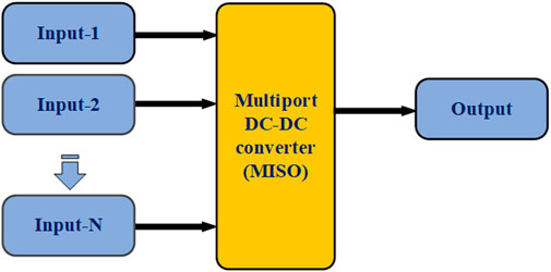
FIGURE 1. Multiple Input Single Output (MISO) topology block diagrams.
The integration of microgrids in a unique and flexible interconnect framework is described in this paper. The basic structure and analysis of the proposed MPC are discussed inSection 3. This converter features two input ports for availing renewable energy sources, each of which may be switched on independently and concurrently at the load, a two-way port for managing storage and backup power supplies, and a fully controlled output port.
2 Literature survey
In order to create the renewable energy-based multi-port system for stability in the proposed system, it is critical to identify the limitations of the conventional methodologies listed below.
The main objective of a general configuration is based on a hybrid AC/DC multi-port and multi-function (MPMF-PET) grid, equivalent circuits and MPMF-PET mathematics modeling (Yang et al., 2019). The process of boosting the power in the grid system consists of two compensation stages. Several interleaved Boost converters have been proposed based on the low ripple of interleaved structures for high power applications (Xu R. et al., 2019). On the other hand, the voltage gain was insufficient for low-voltage renewable energy generation systems. The voltage gain is improved using transformer technology. However, this increases the converter’s volume, lowering its power density and efficiency and Interphase Coupling was used in this study (Tu et al., 2018). However, this resulted in hysteresis and ripples of current loss, lowering the converter’s efficiency. Furthermore, the leakage inductance can easily cause voltage spikes across the switches, necessitating voltage clamping techniques to keep the voltage stresses on the switches to a minimum (Shao et al., 2019). By using neural network back propagation approach (Sankarananth and Sivaraman, 2022) developed a multi port DC-DC converter with various operating modes like single input single output, dual input single output, single input dual output system, describes higher performance and fast dynamic response.
Soft-switching converters are used to reduce switching losses and, as a result, improve efficiency. However, it has a limitation: a rise in voltage across the switch during resonance (Rouhani and Kish, 2020). The multi-input-based converter has a higher efficiency than a traditional interleaved boost converter—the use of coupled inductors to boost each cell’s ripple current. Based on the output characteristic plot of each cell, a positive coupling coefficient will only produce the desired result (Elrayyah, 2019; Ren et al., 2019). Peak current-mode control is a control method used in Pulse Width Modulated (PWM) DC-DC converters because of its quick response, precision, and overburden protection (Samith and Rashmi, 2016), (Guo et al., 2015).
A Dual Active Bridge (DAB) converter is used in the first stage of the process to reduce current sharing errors in the DC system; in the second stage, the Zero sequence Voltage vector is used in the cascaded H-bridge-based grid interconnected with a hybrid AC/DC multi-port system for power flow stabilization (Liu and Liu, 2019; Xu W. et al., 2019). A multi-port power electronic transformer is employed to perform high-rate hybridization of AC and DC multi-stage and varied distributed renewable energy sources. Due to AC/DC, conversion power grid and loads may be efficiently integrated using energy storage systems. The system analyses and simulates the dependability and functioning of the AC/DC hybrid power system in detail, and power reliability calculations are done (Shao et al., 2019).
However, Closed-loop control, which can be implemented using various control techniques, is required for the apparatus to maintain a constant output voltage even when the load and source change. It is also required for better gate switching. Interleaving is a technique for reducing input current ripple that also impacts the converter’s efficiency (Barrera-Cardenas, Mo and Guidi, 2019), (Shojaie and Mohammed, 2018).
A more efficient converter operation is achieved by selecting the correct number of phases and switching frequency. Several factors influence the outcome, including cost, weight, volume, switch conduction losses, inductor volume index, input current, and voltage ripples (Petino, Ruffing and Schnettler, 2017; Zheng et al., 2019). The unregulated DC input is converted into a controlled DC output at the desired voltage level using an interleaved boost converter. In recent years, converter topologies for high-power applications have gotten much attention (Ahmed, Eltantawy and Salama, 2018; Zhu et al., 2019).
Li et al. (2022) proposed a reconfigurable and scalable based multiport converter that arrest cross regulation effects. Also, flexi power flow control on both bi-directional and uni-directional power flow achieved and independent control among ports with switchable configuration among SISO, MISO and MIMO.
The proposal is for a Serial Input and Parallel Output model that can operate in both buck and boost modes. Power switches and a linked inductor with an equal number of turns in both primary and secondary windings make up the suggested converter. Zero-voltage switching can turn on power switches, reducing switching loss and significantly improving conversion efficiency (Jabbari and Dorcheh, 2018). The linked inductor operates in parallel charge and series discharge mode in boost mode. The power flow is reversed in buck mode. The linked inductor was used in parallel charge parallel discharges in this case. Compared to a standard converter, this converter has higher gain values in both the forward and reverse power flow (Faraji, 2018; Wang et al., 2018).
However, increased leakage current and current stress are significant disadvantages, and designing a circuit with few switching devices and a capacitor is difficult (Kardan, Alizadeh and Banaei, 2017), (Danyali, Hosseini and Gharehpetian, 2014). Furthermore, because armature currents are difficult to manage, significant copper losses occur on the low-voltage side, and all energy is transmitted from the large fundamental, reversible DC-DC converters with converter constructions that are not appropriate for use in sources of power with broad supply voltages (Mendola et al., 2019). In this method, a high-efficiency bidirectional converter, the number of components must be kept to a minimum, and optimum transformer performance must be ensured. This report explains a bidirectional converter with a linked inductor that only requires three switches to provide high step-up and step-down (Zhang et al., 2018; Sitharthan et al., 2022).
A double-pulse test was used to describe the defection, and an adaptive dead-band control was used to explain better the optimal dead-band and its primary affecting elements (Faraji, Farzanehfard and Kampitsis, 2020). High-frequency standalone unidirectional DC-DC converter with a voltage output range: control techniques Provides practical techniques and mindsets for developing innovative architectures and control for standalone unidirectional DC-DC converters with an extensive voltage range (Behjati and Davoudi, 2012). Improves the performance of isolated unidirectional DC-DC converters with a voltage output range by introducing new topology and control techniques (Xioa et al., 2017; Madhana and Mani, 2022).
The major findings and features of the proposed system are as listed below.
• An intelligent power interface that promotes effective energy management inside the microgrid by allowing flexible, adaptable, and bidirectional energy flow between the microgrid and the various ports.
• The proposed converter features two input ports for availing renewable energy sources, each of which may be switched on independently and concurrently at the load, a two-way port for managing storage and backup power supplies, and a fully controlled output port.
• To improve the system’s efficiency, reliability, and economy.
• To enable real-time data collection from a wide range of equipment (including RES, electrical equipment, and loads) and providing wide-area data collection of these data from the main grid control center to the microgrid or load forecast operation for status monitoring and troubleshooting.
This paper has been proposed a novel PEAA algorithm for superior energy management control among various ports in the MPC with the objective of improving systems efficiency and quality such as THD and speed up the steady state response of the system.
3 Proposed system
Figure 2 depicts a multi-port DC-DC power converter with the power inverter as part of a multi-source, grid-connected, two-stage hybrid renewable energy system. The DC-DC converter links several sources to multiple input ports, such as Photovoltaic (PV) modules and battery-based energy management. The multi-port DC-DC power converter may perform PEAA control functions for various renewable sources, such as tracking the Maximum Power Point (MPPT) and converting the source’s DC output to the regulated DC voltage necessary for the inverter input. Figure 3 demonstrates the modeling of distributed energy sources in the MATLAB/SIMULINK environment.
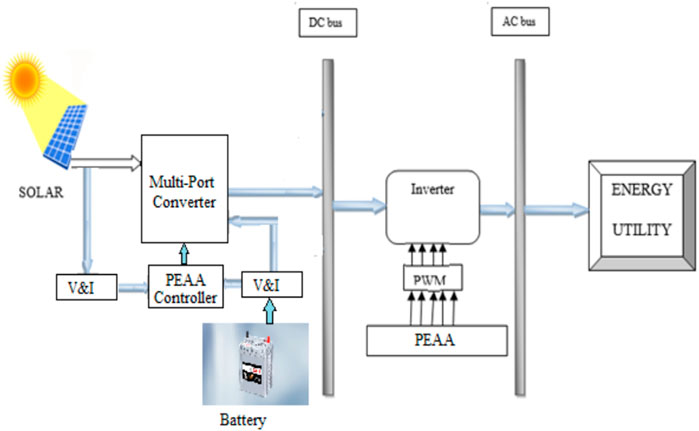
FIGURE 2. Proposed Multi-port converter using Predictive Energy Amendment Algorithm.
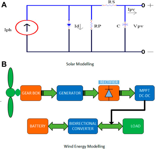
FIGURE 3. Design blocks of Distributed generators.
Power transmission from renewable sources to other power sources must be carefully managed if sustainability and power quality issues are to be resolved. As a result, a system has been conceived to avoid power interruptions and overvoltage and Undervoltage activities so that grid power can function correctly. The power management system is automated and efficiently optimized using a multi-port converter using the Predictive Energy Amendment Algorithm (PEAA). Finally, the inverter for the grid-connected application is given the stabilized DC outage.
3.1 Solar power generation
The SPV system comprises many solar cells coupled in series and parallel to generate voltage. An SPV frame often provides a non-linear voltage. The silicon PV cells are used to create energy from the absorption of solar rays. Each SPV cell’s output is produced from solar radiation and varies regularly. The equivalent circuit is shown below.
3.1.1 Equivalent circuit model of photovoltaic panel
Figure 3A shows an equivalent circuit model of the solar module based on the single diode model proposed. This PV model is employed for all applications because its structure is simple and more dependable than other multi-diode models. The PV module designed using the equivalent circuit must satisfy the real-time characteristics of a realistic PV panel, such as open-circuit voltage, short circuit current, maximum voltage, and power rating.
In the above equation, the solar array’s current and voltage are represented by
An MPPT is often used in modeling and a standalone application to gather the most incredible power from a given solar array. In Equation 2_, VMPP stands for nominal voltage and current, and
The MPPT voltage of a PV panel is acquired using this approach by monitoring the panel’s open-circuit voltage and short circuit current and feeding it into the controller. The MPP voltage and currents are always a constant and maybe a fraction of the open-circuit voltage and short-circuit current in this approach. The constant
A stable solar power generating system is based on a DC-DC converter and an MPPT-based control technique.
3.2 Wind power generation
Wind energy is critical to developing a low-carbon economy that is ecologically sustainable. This project examines the development of wind energy technology for wind energy applications. Special attention has been committed to their involvement in this analysis’s design, control, and theoretical operational issues. The functional block diagram for the wind energy generating and distribution system is shown in Figure 3B.
In the wind power system, the kinetic energy of the wind flow system will be utilized to create electricity. The mathematical analysis based on wind power generation is shown in the equations below.
The wind movement of air (M) is the mass flow rate of the wind blowing across the area (A) is represented by the velocity V (m/s).
As a result, the energy acquired by moving kinetic energy or wind per second equals the energy gained by moving kinetic energy or wind per second.
The equation replaces the wind’s power with the mass flow rate.
The equation below gives the most accurate wind energy density estimate.
N is the number of wind speed readings, and ρj and Vj are the air’s density and the wind’s speed.
3.3 Proposed Multiport bidirectional DC-DC converter
Figure 4 shows the proposed isolated three-port Bi-directional Converter (BDC). A Low Voltage Side (LVS) circuit and a High Voltage Side (HVS) circuit are connected by a high-frequency transformer with the center tap on the secondary side. A PV system is linked to a unidirectional port (Port 1), while a battery in the LVS circuit is connected to a bidirectional port (Port 2). The transformer’s secondary winding is connected to switches Q3 and Q4, a low-frequency LC filter, and Port 3, which in the HVS circuit can be connected to a DC load or a DC microgrid. The power generated by the PV system linked to Port 1 is controlled by the main switch among the switches Q1 (P1). The wind system is connected in (P2), and the current flowing through the transformer is in the proper direction. Np and Ns are the primary and secondary winding turn, respectively, and n = Np/Ns is the turn ratio. The capacitances in the circuit are assumed to be sufficiently large to prevent voltage changes across them during the switching period to simplify the problem’s solution.
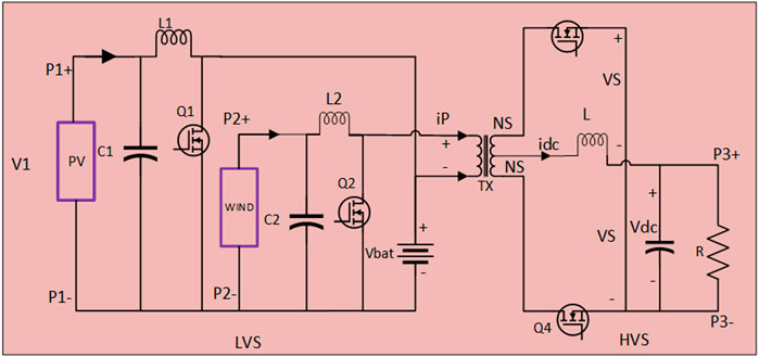
FIGURE 4. Proposed isolated, three-port, bidirectional DC-DC converter.
Solar and wind electricity may charge the battery and supply the load in a DC microgrid since the power transmission between the LVS, and the HVS is bidirectional. In typical applications, the converter has two operating modes: 1) boost mode, which flows from the LVS to the HVS; and 2) buck mode, which power flows from the HVS to the LVS. Based on the potential directions of the power flow in the two operating modes, there are four alternative working scenarios for the proposed converter, as.
State 1: The PV system charges the battery.
State 2: The DC microgrid receives the energy generated by the PV system.
State 3: The battery is exhausted to power the DC microgrid.
State 4: the battery is charged by DC microgrid power.
The states 1, 2, and 3 are in boost mode, whereas state four is in buck mode. The converter’s working mode does not affect the battery’s power management; the battery can be charged or discharged in either boost or buck mode. As a result, the buck-boost converter in Port 2 (see Figure 4) performs poorly compared to Port 1. The following two subsections examine Port 1’s interactions with the HVS in two separate modes.
3.3.1 Boost mode operation
In this mode, the Q1 and Q2 are active, while the switches Q3, Q4, and internal diodes on the HVS form a rectifier. The converter has two operational phases, depending on the status of the switch Q1. The equivalent circuits and steady-state waveforms of the converter’s two operational stages (excluding Port 2) are illustrated in Figure 5A,B, respectively.
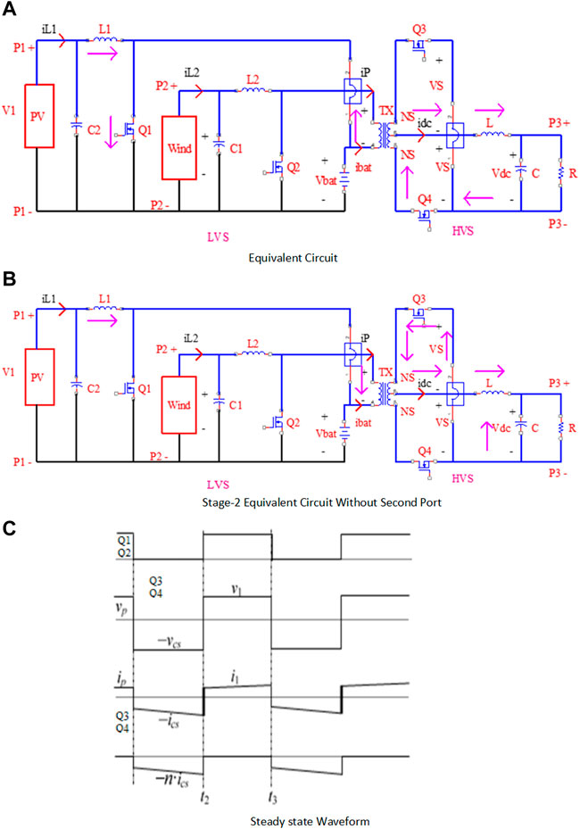
FIGURE 5. The proposed converter’s study in stage-1 operation.
Stage 1: When Q1 and Q2 are active, t (t1, t2). Figure 5A shows the equivalent circuit at this step, with the inductor L1 storing energy and the capacitor Cs discharging through the transformer and switching Q1 and Q2. The voltage across the primary side of the transformer, VP, is negative, causing the internal diode of the HVS switch Q4 to conduct. The HVS receives the energy stored in the capacitor Cs via the internal diode of the switch Q4.
Stage 2: When Q1 and Q2 are switched off, t (t1, t2). The energy stored in L1 during Step 1 is delivered to the HVS through the transformer during this stage, simultaneously charging the capacitor Cs. The current flows from switch Q4’s internal diode to switch Q3 through the HVS.
The proposed converter’s steady-state waveforms in boost mode (without Port 2). The differential equations are the same as in (10) in both stages.
3.3.2 Buck mode operation
When switch Q1 is disabled in this mode, switches D1 and D2 are active and transport power from the HVS to the LVS. Figures 5A,B,C show the converter’s steady-state waveforms and identical circuits (without Port 2) for four distinct operation stages. The gate signals of switches Q3 and Q4 (Q3∗ and Q4*, respectively) complement one another to avoid commutation, as illustrated in Figure 7B.
Stage 1: t (t1, t2) (see Figure 7), when Q3 is turned off and Q4 is turned on (Q3* = 0 and Q4* = 1). In this level, the corresponding circuit is shown in Figure 5C. When S4 is turned on, the voltage on the transformer’s secondary side, vs, is positive; when S1 is turned on, the internal diode of the switch Q1 and Q2 is turned on, and VP is clamped to VCs. The current IP is moving positively. The HVS sends energy to the LVS, stored in capacitor Cs. The stored energy will be used to charge the battery using the buck-boost circuit linked to Port 2, as shown in Figure 5C.
Stage 2: t (t2, t3), when Q3 and Q4 are disabled (Q4* = 0 and Q4* = 0). Figure 6A shows the corresponding circuit in this stage. The current via the inductor L, idc, charges the parasitic capacitor of the switch Q4, and the equation follows.
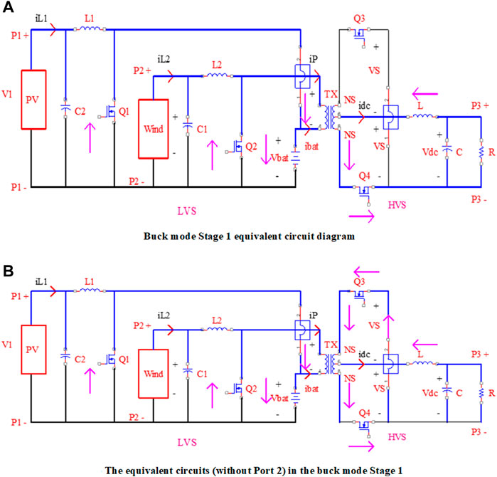
FIGURE 6. The proposed converter’s study in boost mode without port-2.
V_(ds 3) and V_(ds 4) represent the voltages across the switches Q3 and Q4, respectively, and vs. represents the voltage across the transformer’s secondary side. Because vs. is a constant value, i.e., V_s = vcs/n, if vds4 increases, vds3 decreases, as seen in 1). Specifically, when V_(ds 4) = −2vs, V_(ds 3) = 0, which gives the switch S3 the ZVS condition.
Assume that the switch Q4’s parasitic capacitor is fully charged within time t and has a peak voltage of 2vcs/n.
Where C_oss is the switch Q4’s parasitic capacitance. Based on the ∆t can be determined as;
If the ZVS of the switch Q3 is less than the time length of this stage, especially if it is less than the time length of this stage, it can be achieved. Inequality 4) reveals that for the switch Q3 to accomplish the ZVS, a more significant current via the inductor L is preferable.
Stage 3: t (t3, t4), when Q3 is active and Q4 is inactive (Q3* = 1 and Q4* = 0). Figure 6B shows the corresponding circuit in this stage. When Q3 conducts, the transformer’s volt-second balance is maintained, resulting in VP = VCs. There is no power transmission between the HVS and the LVS since IP = 0.
Stage 4: t (t4, t5), when Q3 and Q4 are both turned off (Q3* = 0 and Q4* = 0). In this level, the corresponding circuit is represented in Figure 7A. The ZVS of the switch Q4 can be done similarly to the analysis in Stage 2. Stage 4 changes to Stage 1 when the switch Q4 is turned on at time t5.
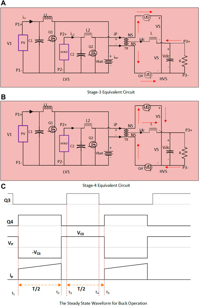
FIGURE 7. The proposed converter’s study in buck mode in stage 3 and 4 without port-2.
3.4 Voltage source inverter
The circuit diagram for a bridge-type voltage source inverter with a three-phase connection and square wave pole voltages is shown in Figure 7C. The 3-phase balanced load causes it to feed as an inverter output. This inverter power circuit comprises three single-segment semi-bridge inverters with their circuits connected to the same DC bus. This bridge circuit’s pole voltages are the same as the square voltage output by a single-phase half-bridge or full-bridge circuit. The three-pole voltage of a 3-phase square wave inverter is commonly changed by one-third of the output periods.
The six variations simulated on a release cycle six indicate the conducting switches. They are (S5, S6, and S1) (S6, S1, S2), (S1, S2, S3), (S2, S3, S4), (S3, S4, S5), (S6, S1, S2), (S1, S2, S3), (S2, S3, S4), and (S3, S4, S5) (S4, S5, S6) as in Table 1. The essential components of the three output line voltages are balanced; therefore, such linked switches will generate a sequence of sequences in a 600-point display of A, B, and C. The wavelengths of load side-phase voltages are entirely different from the polar voltage wavelengths that will be dealt with in the following behavior.
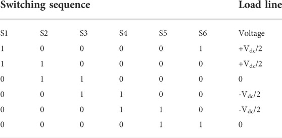
TABLE 1. Switching sequence.
As with the single-phase square wave inverter, the switches in each leg of the three-phase inverter are discovered to operate in a complementary way. When an upper switch is set to the low position, the voltage and fluctuation of the entire DC bus will be affected. When it comes to DC bus voltage, the switches must be examined to avoid power, and it seems that each inverter switch carries the load-phase current for half of the current cycle. As a result, the switches must be able to instantly resist the amount of load-phase current. When the diode is connected anti-parallel to the switch, a non-unity power factor load is distributed.
3.5 Predictive energy amendment algorithm
The steps necessary to build a Grid-tied Renewable Energy Stability System. The technique approach proposed here, the Predictive Energy Amendment Algorithm (PEAA), is logical, and a step-by-step procedure is provided below.
Step 1: Initialization of devices.
Step 2: Initially, Source power is in ON condition.
Step 3: Devices are run with DC power.
Step 4: The Predictive Energy Amendment Algorithm (PEAA) controller is programmed to monitor solar and grid power.
Step 5: If the solar power is varied below the threshold, the Predictive Energy Amendment Algorithm (PEAA) regulates the PWM control signal to the Full bridge converter until
Step 7: In a PEAA controller, the stored energy is always compared with pre-setting levels.
Step 8: The stabilized power is given to the inverter.
Where,
Step 9: calculate the d-axis and q-axis components of the voltage of the grid system.
Step 10: Comparison between terminal
Step 11: The control of Predictive Energy Amendment Algorithm (PEAA) reference optimized voltages are computed from the various load and source voltage.
Step 12: This three-phase injected reference voltage is supplied to the PWM voltage controller.
Step 13: The average value of this function and the filter output depends on the positive line’s actual power consumption.
Step 14: Stop.
4 Result and Discussion
The MATLAB Simulink software used the environment to create the suggested Predictive Energy Amendment Algorithm (PEAA) Strategy-based Hybrid Multi port converters. Figure 8 shows the simulation model in detail. A Power Predictive Energy Amendment Algorithm (PEAA) will be required to balance the power while maintaining the DC voltage in this simulation, primarily when the system works under various situations.
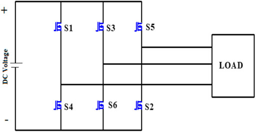
FIGURE 8. Three Phase Inverter Circuit.
In this simulation model, Hybrid Multi port DC-DC converters indicate the diverse power generating models named Wind power and solar power with battery-based energy management, as shown in the above diagram.
Figure 9 shows the solar Voltage waveform of the proposed model from their presentation of the solar generation has been a distortion in the output voltage; the generated voltage will be stabilized with fewer ripple ratios by using the proposed DC-DC converter with the Predictive Energy Amendment Algorithm (PEAA) control strategy.
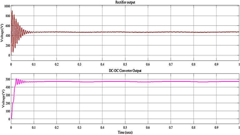
FIGURE 9. Wind-based DC-DC converter waveform.
As seen in Figure 9, the actual wind power generation varies in the output waveform. The grid and load stability operations could not be transferred into the grid system because of the grid.
Figure 10 depicts two different waveforms of the wind generation system: (I) the rectified output voltage of the wind generation, which stabilizes the winding voltage in the DC system; and (II) the proposed DC-DC converter with the Predictive Energy Amendment Algorithm (PEAA) control system, which will stabilize the rectified output voltage of the winding voltage.
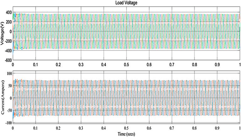
FIGURE 10. Grid Voltage and Current Waveform.
The energy management process begins with the batter system, which is charging during the power generation of renewable energy resources. If there is energy uncertainty, the battery power is delivered to stabilize the power, and this process is applied to the charging state of the battery shown in Figure 9.
The generated power will be transformed into a DC-AC process, and the suggested Predictive Energy Amendment Algorithm (PEAA) method will give the stabilized output of both voltage and current for the grid-tie system of both AC and DC, as shown in Figure 10.
Figure 11 shows the THD analysis of the proposed Hybrid Multiport Converter model utilizing the Predictive Energy Amendment Algorithm (PEAA) management technique, which results in a THD Ratio of 0.13%.
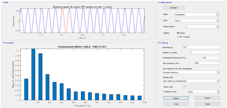
FIGURE 11. THD analysis.
Table 2 shows the performance of the hybrid multi-port converter system based on the parameters of execution time (sec), steady-state error (%), THD (percent), and efficiency in (%); based on the comparison of all those parameters, the proposed Predictive Energy Amendment Algorithm (PEAA) control strategy produces an efficient result when compared to other conventional methods such as Proportional Integral Derivative (PID) and Assimilate Power Flow Control (APFC). Moreover, Table 2 clearly shows that PEAA efficiency is 2.34% higher than APFC and 6.88% greater than conventional PID controller with less THD and faster response of about 0.231 s which proves its superiority characteristics.
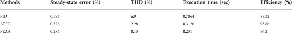
TABLE 2. Performance analysis of the Hybrid multi-port converter system.
Figure 12 shows a comparison of the hybrid multi-port converter system; based on the execution time of 0.231 s, steady-state inaccuracy of 0.284%, and THD of 0.13%, the suggested Predictive Energy Amendment Algorithm (PEAA) generated a superior result than the conventional techniques.
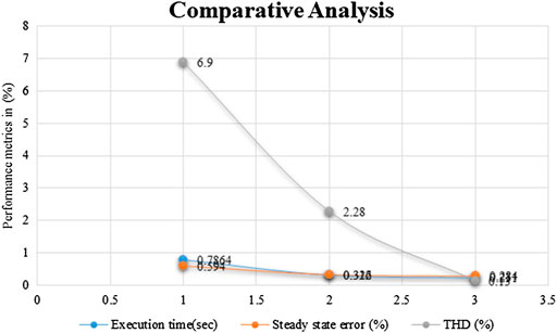
FIGURE 12. Comparative analysis.
Figure 13 illustrates the efficiency analysis of the proposed system, demonstrating that the suggested Predictive Energy Amendment Algorithm (PEAA) control approach outperforms previous techniques.
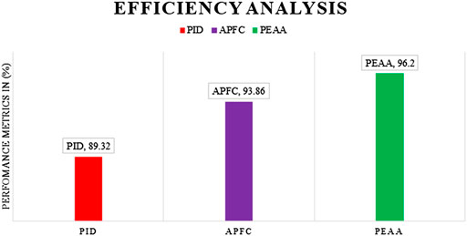
FIGURE 13. Efficiency analysis.
5 Conclusion
For an efficient energy management system in the innovative grid application, this paper proposed a Predictive Energy Amendment Algorithm (PEAA) control technique in the hybrid multi-port converter system. The simulation is based on the simulated hybrid multi-port grid system’s dynamic model. This model may be used to learn how to keep the multi-power generation’s parameters under control using battery-based energy management. The suggested intelligent energy management system shows the minimum operating expenses and the environmental effect of microgrids while considerably enhancing the power generating system’s economic and efficiency. During the Hybrid multi-port converter’s operation, the suggested PEAA control guarantees power management between renewable energy generation, energy storage, and load. Analogized to traditional approaches, the simulation results demonstrate that the controller performs well under execution time of 0.231 s, steady-state error of 0.284%, and THD of 0.13%, with an efficiency of 96.2%. Moreover, the proposed converter ensures the superior energy management for both unidirectional and bidirectional ports for RES, load and battery, considering all the cases, also it avoids the cross regulation effect. The prototype needs to be developed as an extension of this work to benchmark the proposed system characteristics to the market availability.
Data availability statement
The original contributions presented in the study are included in the article/supplementary material, further inquiries can be directed to the corresponding author.
Author contributions
The Authors RM and GM has been conceived the presented idea. Both authors developed the theory and performed the computations. Both authors equally contributed to validating the analytical methods. GM encouraged RM to investigate MPC and supervised the findings of this work. All authors discussed the results and contributed to the final manuscript.
Conflict of interest
The authors declare that the research was conducted in the absence of any commercial or financial relationships that could be construed as a potential conflict of interest.
Publisher’s note
All claims expressed in this article are solely those of the authors and do not necessarily represent those of their affiliated organizations, or those of the publisher, the editors and the reviewers. Any product that may be evaluated in this article, or claim that may be made by its manufacturer, is not guaranteed or endorsed by the publisher.
References
Ahmed, H. M. A., Eltantawy, A. B., and Salama, M. M. A. (2018). A generalized approach to the load flow analysis of AC-DC hybrid distribution systems. IEEE Trans. Power Syst. 33 (2), 2117–2127. doi:10.1109/TPWRS.2017.2720666
Barrera-Cardenas, R., Mo, O., and Guidi, G. (2019). “Optimal sizing of battery energy storage systems for hybrid marine power systems,” in Proceedings of the 2019 IEEE Electric Ship Technologies Symposium, ESTS, Washington, DC, USA, August 2019, 293–302. doi:10.1109/ESTS.2019.8847932
Behjati, H., and Davoudi, A. (2012). Single‐stage multi‐port DC-DC converter topology. IET Power Electron. 6 (2), 392–403. doi:10.1049/iet-pel.2012.0339
Danyali, S., Hosseini, S. H., and Gharehpetian, G. B. (2014). New extendable single-stage multi-input DC-DC/AC boost converter. IEEE Trans. Power Electron. 29 (2), 775–788. doi:10.1109/TPEL.2013.2256468
Elrayyah, A. (2019). “Control algorithms to establish hybrid AC/DC distribution systems using conventional three phase inverters,” in Proceedings of the 2019 IEEE Energy Conversion Congress and Exposition, ECCE, Baltimore, Maryland, USA, October 2019, 6246–6253. doi:10.1109/ECCE.2019.8912509
Faraji, R., Farzanehfard, H., Kampitsis, G., Mattavelli, M., Matioli, E., and Esteki, M. (2020). Fully soft-switched high step-up nonisolated three-port DC–DC converter using GaN HEMTs. IEEE Trans. Ind. Electron. 67 (10), 8371–8380. doi:10.1109/tie.2019.2944068
Faraji, R., and Farzanehfard, H. (2018). Soft-switched nonisolated high step-up three-port DC–DC converter for hybrid energy systems. IEEE Trans. Power Electron. 33 (12), 10101–10111. doi:10.1109/tpel.2018.2791840
Guo, W., Xiaoqing, H., Chunguang, R., and Peng, W. (2015). “The control method of bidirectional AC/DC converter with unbalanced voltage in hybrid micro-grid,” in Proceedings of the 2015 10th IEEE Conference on Industrial Electronics and Applications, ICIEA, 381–386. doi:10.1109/ICIEA.2015.7334143
Jabbari, M., and Dorcheh, M. S. (2018). Resonant multi-input/multi-output/bidirectional ZCS step-down DC-DC converter with systematic synthesis for point-to-point power routing. IEEE Trans. Power Electron. 33 (7), 6024–6032. doi:10.1109/TPEL.2017.2749326
Kardan, F., Alizadeh, R., and Banaei, M. R. (2017). A new three input DC/DC converter for hybrid PV/FC/battery applications. IEEE J. Emerg. Sel. Top. Power Electron. 5 (4), 1771–1778. doi:10.1109/JESTPE.2017.2731816
Li, X. L., Chi, K. T., and Lu, D. D. C. (2022). Synthesis of reconfigurable and scalable single-inductor multiport converters with no cross regulation. IEEE Trans. Power Electron. 37 (9), 10889–10902. doi:10.1109/TPEL.2022.3167119
Liu, X., and Liu, Y. (2019). Optimal planning of AC-DC hybrid transmission and distributed energy resource system: Review and prospects. CSEE J. Power Energy Syst. 5 (3), 409–422. doi:10.17775/cseejpes.2019.00540
Madhana, R., and Mani, G. (2022). Power enhancement methods of renewable energy resources using multiport DC-DC converter: A technical review. Sustain. Comput. Inf. Syst. 35. doi:10.1016/j.suscom.2022.100689
Mendola, M. L., Benedetto, M., Lidozzi, A., Solero, L., and Bifaretti, S. (2019). “Four-port bidirectional dual active bridge converter for EVs fast charging,” in Proceedings of the 2019 IEEE Energy Conversion Congress and Exposition, ECCE 2019, 1341–1347. doi:10.1109/ECCE.2019.8912252
Petino, C., Ruffing, P., and Schnettler, A. (2017). Intersystem fault clearing in hybrid AC/DC power systems with full bridge modular multilevel converters. IET Conf. Publ. 2017 (CP709), 2–7. doi:10.1049/cp.2017.0020
Ren, C., Liu, L., Han, X., Zhang, B., Wang, L., and Wang, P. (2019). “Multi-mode control for three-phase bidirectional AC/DC converter in hybrid microgrid under unbalanced AC voltage conditions,” in Proceedings of the 2019 IEEE Energy Conversion Congress and Exposition, ECCE, 2658–2663. doi:10.1109/ECCE.2019.8912259
Rouhani, M., and Kish, G. J. (2020). Multiport DC–DC–AC modular multilevel converters for hybrid AC/DC power systems. IEEE Trans. Power Deliv. 35 (1), 408–419. doi:10.1109/tpwrd.2019.2927324
Samith, M. V., and Rashmi, M. R. (2016). “Controller for integrating small scale power generation to hybrid AC/DC grid,” in Proceedings of the International Conference on Inventive Computation Technologies, ICICT. doi:10.1109/INVENTIVE.2016.7830098
Sankarananth, S., and Sivaraman, P. (2022). Performance enhancement of multi-port bidirectional DC-DC converter using resilient backpropagation neural network method. Sustain. Comput. Inf. Syst. 36, 100783. doi:10.1016/j.suscom.2022.100783
Shao, Y., Deng, X., Lu, S., and Li, S. (2019). “A new multi-port power electronic transformer for distribution grid,” in Proceedings of the 2019 22nd International Conference on Electrical Machines and Systems, ICEMS. doi:10.1109/ICEMS.2019.8921513
Shojaie, M., and Mohammed, O. A. (2018). “A multi-input DC-DC converter with AC-DC PFC buck-boost stage for hybrid energy storage systems,” in Proceedings of the Conference Proceedings - IEEE SOUTHEASTCON 201, April 2018, 1–5. doi:10.1109/SECON.2018.8478879
Sitharthan, R., Madurakavi, K., Jacob Raglend, I., Palanisamy, K., Belwin Edward, J., Rajesh, M., et al. (2022). Performance enhancement of an economically operated DC microgrid with a neural network–based tri-port converter for rural electrification. Front. Energy Res. 10, 1–14. doi:10.3389/fenrg.2022.943257
Tu, C., Guan, L., Xiao, F., and Lan, Z. (2018). “Study on an novel multi-port energy router for AC-DC hybrid microgrid,” in Proceedings of the 13th IEEE Conference on Industrial Electronics and Applications, ICIEA, 2654–2659. doi:10.1109/ICIEA.2018.8398159
Wang, Y., Han, F., Yang, L., Xu, R., and Liu, R. (2018). A three-port bidirectional multi-element resonant converter with decoupled power flow management for hybrid energy storage systems. IEEE Access 6, 61331–61341. doi:10.1109/ACCESS.2018.2872683
Xioa, Q., Jia, H., Liang, B., and He, J. (2017). “Current balancing control for multi-port hybrid AC/DC microgrid,” in Proceedings of the IEEE Power & Energy Society General Meeting 1–5. doi:10.1109/PESGM.2017.8273788
Xu, R., Wu, X., Liu, H., Zhou, Z., Yin, H., Lan, T., et al. (2019). “Research on control strategy for multi-port power electronics transformer based on Interphase coupling MMC topology,” in Proceedings of the 2019 22nd International Conference on Electrical Machines and Systems, ICEMS 2019, 1–5. doi:10.1109/ICEMS.2019.8922102
Xu, W., Li, A., Su, Y., Zhu, M., Ouyang, X., and Yang, X. (2019). “Optimal expansion planning of AC/DC hybrid system integrated with VSC control strategy,” in Proceedings of the 2019 IEEE PES Innovative Smart Grid Technologies Asia, ISGT, 3272–3276. doi:10.1109/ISGT-Asia.2019.8881734
Yang, Y., Pei, W., Deng, W., and Zhang, S. (2019). “Benefit analysis of using multi‐port and multi‐function power electronics transformer connecting hybrid AC/DC power grids,” in Proceedings of the the 14th IET international conference on AC and DC power Transmission (ACDC 2018). IET Journals, 1076–1080. doi:10.1049/joe.2018.8446
Zhang, C., Campana, P. E., Yang, J., Yu, C., and Yan, J. (2018). Economic assessment of photovoltaic water pumping integration with dairy milk production. Energy Convers. Manag. 177, 750–764. doi:10.1016/j.enconman.2018.09.060
Zheng, Z., Zheng, J., Zhao, W., and Han, Z. (2019). “Research on dynamic voltage characteristics of AC/DC hybrid system based on PET,” in Proceedings of the 2019 IEEE PES Innovative Smart Grid Technologies Asia, ISGT, 270–274. doi:10.1109/ISGT-Asia.2019.8881201
Zhu, Y., Shi, S., Cheng, S., Ding, R., Du, X., and Zhuo, F. (2019). “Topology, modulation and control strategy of a multi-port DC/DC converter based on modular multilevel converter,” in Proceedings of the PEDG 2019 - 2019 IEEE 10th International Symposium on Power Electronics for Distributed Generation Systems, 599–603. doi:10.1109/PEDG.2019.8807722
Keywords: microgrid, multi-port converter (MPC), renewable energy power generation, battery based energy management, predictive energy amendment algorithm (PEAA)
Citation: Madhana R and Mani G (2022) Design and analysis of the multi-port converter based power enhancement for an integrated power generation system using predictive energy amendment algorithm. Front. Energy Res. 10:1000242. doi: 10.3389/fenrg.2022.1000242
Received: 21 July 2022; Accepted: 30 September 2022;
Published: 24 October 2022.
Edited by:
Haris Ishaq, University of Victoria, CanadaReviewed by:
Mohamed Salem, Universiti Sains Malaysia (USM), MalaysiaFaran Razi, University of British Columbia, Canada
Copyright © 2022 Madhana and Mani. This is an open-access article distributed under the terms of the Creative Commons Attribution License (CC BY). The use, distribution or reproduction in other forums is permitted, provided the original author(s) and the copyright owner(s) are credited and that the original publication in this journal is cited, in accordance with accepted academic practice. No use, distribution or reproduction is permitted which does not comply with these terms.
*Correspondence: Geetha Mani, R2VldGhhLm1hbmlAdml0LmFjLmlu