- Nanjing Institute of Technology, Nanjing, China
Under the condition of weak grid, the coupling between parallel inverters and grid impedance is easy to cause harmonic resonance, which seriously affects the grid-connected power quality. First, the equivalent circuit model of the multi-inverter parallel system is established, and the mechanism of harmonic resonance is analyzed from the perspective of impedance; through the resonance detection method based on a self-tuning filter, the voltage resonance component of the parallel node is extracted; on that basis, an active impedance is designed to suppress the resonance of the multi-inverter parallel system, which can equivalently construct a virtual impedance branch to improve the grid impedance characteristics at the resonance frequency, and its effectiveness is verified using the impedance stability criterion. Finally, simulation experiments are carried out. The results show that this method can effectively suppress the resonance of the multi-inverter parallel system and can significantly improve the adaptability of inverters to weak grid.
1 Introduction
With the continuous advancement of the global energy structure transformation process, the proportion of renewable energy such as wind energy and solar energy connected to the utility grid is gradually increasing. The research on the grid-connected inverter has attracted people’s attention (Hong et al., 2019; Xiong et al., 2020; Akhavan et al., 2021). In the actual system, considering the factors such as long-distance transmission lines and transformer leakage reactance, the connection between the new energy power generation link and the utility grid becomes weaker, which makes the utility grid to show the characteristics of weak grid. In the environment of weak grid, there is interaction coupling between inverters and utility grid, which increases the risk of harmonic resonance of the system, and may lead to global resonance instability of the system in serious cases (Zhang et al., 2016; Lu et al., 2019; Fang et al., 2021; Xiong et al., 2021).
At present, the research on the resonance mechanism and resonance suppression method of the multi-inverter parallel system is a research hot spot of new energy grid connection technology (Yu et al., 2019). Different from the single inverter, the resonance mechanism of the multi-inverter parallel system is more complex. Through calculation and analysis, it has been shown in Zhen-Ao et al. (2014) that there are two resonance frequency points in the multi-inverter parallel system under weak grid: one is the inherent resonance of the LCL-type inverter, and the other is the external coupling resonance between grid impedance and parallel inverters. The equivalent circuit model of the multi-inverter parallel system is established in Agorreta et al. (2011), when n inverters operate in parallel, the equivalent grid impedance of the single grid-connected inverter can be equivalent to n times of the actual grid impedance. Furthermore, it is proposed that with the increase of the number of parallel inverters, the natural resonance of LCL remains unchanged, while the external coupling resonance shifts to low frequency in Hu et al. (2015). In fact, the reason for resonance instability of the multi-inverter parallel system under weak grid lies in the existence of grid inductance, and grid resistance is conducive for improving the stability of the grid-connected system (Pan et al., 2014). Therefore, in the research process, the resistance can be ignored and only the grid inductance is considered.
The resonance suppression methods of the multi-inverter parallel system are mainly divided into single type and centralized type. The former is to reshape the inverter output impedance by adding the state variable feedback link to each inverter control circuit (Yang et al., 2014; Gao et al., 2020; Natori et al., 2020). However, when the number of inverters is large, the single impedance remodeling method needs to modify the control algorithm of each inverter, which is difficult to realize in practical application. From the global point of view, the centralized resonance suppression method can effectively suppress the occurrence of harmonic resonance by reasonably designing the damping circuit at the point of common coupling (PCC). To suppress the resonance of the multi-inverter system, a method of parallel RC branches at PCC is implemented in Wan et al. (2018). That passive suppression circuit is simple in design, but the problem of power loss is serious. Furthermore, Wang et al. (2015) proposed to install an active damper at PCC to effectively construct the resistance at the resonant frequency, so as to improve the damping characteristics of the system at the resonant frequency. This method effectively reduces the power loss but has high requirements for resonant frequency extraction. In view of the idea of the active damper, a global active inductor is designed in Kang (2020), which can realize the approximate parallel virtual inductance at PCC. However, adding virtual inductance will cause the phase angle lag of 90° in the whole frequency band of the system, so it is necessary to add an additional phase angle compensation link. Most of the above resonance suppression methods only deal with the harmonic resonance of specific frequency. However, in the actual system, the grid impedance will fluctuate due to environmental changes and the working condition of inverter switching. The resonance frequency in the system is often time-varying, and the resonance problem in the grid-connected system is more complex.
Considering the complex grid-connected operation conditions of weak grid, active impedance designed to suppress the resonance of the multi-inverter parallel system is discussed in this article. In Section 2, the equivalent model of the multi-inverter parallel system under weak grid is established, and its stability is analyzed by the impedance analysis method. Section 3 presents the main development of this article, which includes the design method of active impedance and its extraction method based on a self-tuning filter. Meanwhile, the influence of active impedance on system stability is analyzed by the Nyquist stability criterion. Finally, the effectiveness and accuracy of the proposed resonance suppression method is verified by simulation in Section 4.
2 Resonance Mechanism Analysis of the Multi-Inverter Parallel System
2.1 Model of the Multi-Inverter Parallel System
The system structure of the T-type three-level inverter based on an LCL filter shown in Figure 1 consists of neutral-point (NP) switches and vertical half-bridge switches, followed by an LCL filter, where Udc is the DC voltage, C1 and C2 are the DC support capacitors with equal capacitance, Lline represents the line impedance from the inverter to PCC, Lg is the equivalent impedance of the grid, ig is the grid-connected current and ug is the grid voltage, and θ is the voltage phase angle. The voltage outer loop adopts PI control, and the voltage outer loop provides the current reference value to the current inner loop. The current inner loop is controlled by QPR to generate the SVPWM modulation signal to drive the inverter.
Figure 2 depicts the current feedback control block diagram of the LCL-type grid-connected inverter. GC(s) is the QPR controller, and H(s) is the feedback used to weaken the inherent resonant peak of LCL and is taken as the combination of quadratic differential link, primary differential link, proportional link, and integral link. Specific design methods are shown in reference (Chen et al., 2013; Xu 2019).
The expression of the grid-connected current can be obtained as:
where
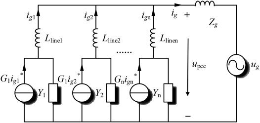
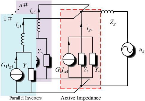
According to the expression of the grid-connected current, the Norton equivalent circuit can be established which includes the controlled current source G1ig1 ∗ and admittance Y1. When multiple inverters operate in parallel in the system, it can be equivalent to the Norton equivalent model of multiple inverters in parallel as shown in Figure 3.
2.2 Resonance Mechanism Analysis
According to the superposition theorem, the expression of the total grid-connected current ig can be deduced:
where Zouti represents the output impedance of the ith inverter, Zouti = sLlinei+1/Yi, and Zop represents the total output impedance of inverters in parallel. When the ratio Tm of grid impedance Zg to output impedance Zop satisfies the Nyquist stability criterion, the grid-connected system can be considered stable (Sun 2011). When the parameters of parallel inverters are the same, Zout = n∗Zop, and the impedance ratio Tm can be written as Eq. 5.
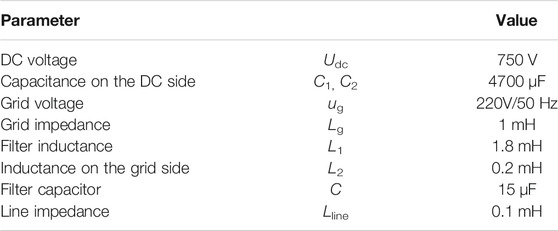
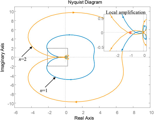
Utility grid impedance Zg = sLg draws the impedance ratio Nyquist curve of single inverter and two inverters in parallel according to Eq. 5, as shown in Figure 4. The parameters of the grid-connected inverter are shown in Table 1.
It can be seen from Figure 4 that when there is only one inverter, the Nyquist curve of Tm(s) does not surround (−1, j0) point and satisfies the impedance stability criterion. However, it should be noted that the curve of the single inverter is close to (−1, j0) point, indicating that the stability margin of the system is relatively low at this time. When the number of inverters in the system increases, the range of the Nyquist envelope becomes larger. When n takes 2, the Nyquist curve of Tm(s) obviously surrounds (−1, j0) point. It can be determined that resonance instability occurs in the multi-inverter parallel system at this time. Therefore, although the single inverter can operate stably, when multiple inverters operate in parallel, the system still has a resonance-hidden danger.
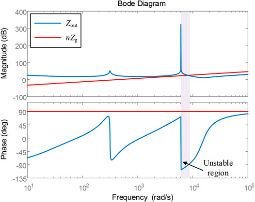
The frequency characteristic curves of inverter output impedance Zout and grid equivalent impedance nZg are drawn, as shown in Figure 5. It can be seen from the figure that there will be an unstable region with a phase difference greater than or equal to 180° between the inverter output impedance and grid impedance in a certain frequency band under the weak grid. When the intersection frequency of the two impedance is in this frequency band, the system is easy to resonate with the harmonics, which is consistent with the results of Nyquist plot analysis.
3 Research on the Resonance Suppression Method
In order to solve the resonance instability problem of the multi-inverter parallel system, from the perspective of system global resonance suppression, it is necessary to extract the resonance signal in the system first and then use the resonance suppression unit installed at PCC for centralized treatment.
3.1 Resonance Detection Method Based on Self-Tuning Filter
The resonance information in the actual grid-connected system is often uncertain and will change with the change of the system. Although the traditional wavelet packet and discrete Fourier transform methods can detect the resonant signal, the extracted information is not accurate enough, the amount of calculation is large, and the detection time is long (Zeng et al., 2014). Therefore, this article adopts the resonance detection method of the grid-connected inverter based on a self-tuning filter (STF). The transfer function GSTF(s) of STF can be expressed as:
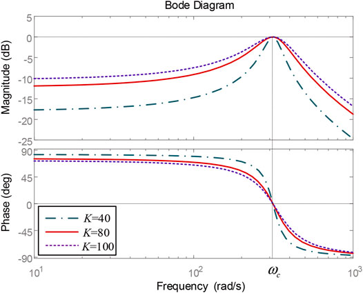
where Uxy is the input signal of STF, Vxy is the output signal, and ωc is the fundamental angular frequency. As long as K takes a positive value, STF can remain stable (Biricik et al., 2014). Based on Eq. 6, the frequency response curve of STF can be obtained as shown in Figure 6.
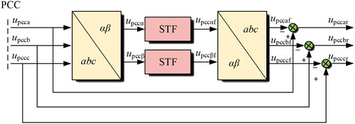
It can be seen from Figure 6 that STF has band-pass filtering characteristics for the input signal, and the output signal is unattenuated only at the angular frequency ωc. Hence, this characteristic of STF can be used to extract the resonant signal. The principle is shown in Figure 7, where the subscript f represents the voltage fundamental component, and the subscript r represents the voltage resonant component.
First, by self-tuning filtering the voltage sampled at PCC, the fundamental frequency component can be tracked without a static difference, and then the resonance voltage can be obtained by subtracting the fundamental frequency voltage from the sampled voltage. Therefore, the resonant detection method based on the self-tuning filter can quickly and accurately filter the fundamental frequency component in the voltage signal and extract the voltage resonant component as the input signal for active impedance.
3.2 Resonance Suppression Strategy Based on Active Impedance
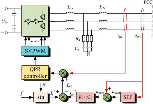
The active impedance is usually installed at PCC, and its topology is similar to APF, as shown in Figure 8. The active impedance designed in this article adopts a T-type three-level DC/AC converter, L1a, Ca, and L2a constitute LCL filter, Ra is damping resistance, and subscript a represents the active impedance. I* is the command current, and the resonance detection module adopts the resonance detection method based on STF. The extracted voltage resonance signal upccr passes through the virtual impedance Rv + sLv to generate the reference value of the current resonance signal iga*, and the sampled output current iga is added to the QPR controller to simulate the parallel passive impedance element at PCC, which increases the damping of the system at the resonance frequency.
Figure 9 is the current loop feedback control block diagram of the active impedance, and Gr(s) represents the STF resonance extraction link. According to the method of deriving the inverter equivalent circuit model in the previous section and combined with Figure 9, the expression of the output current iga can be derived, as shown in Eq. 7.
The Norton equivalent model of active impedance can be obtained, as shown in Figure 10. Ya and Yv represent the output admittance and virtual admittance of the active impedance, respectively.
In which,
where H1(s) and H2(s) represent the admittance characteristics at both ends of the LCL filter, and Gca(s) represent the transfer function of the QPR current controller.
Since the active impedance only works at the resonant frequency, the transfer function of the current controller can be approximated to include only the proportional link Kp. When the system resonates, the transfer function Ga(s) of the controlled source of the active impedance approaches 1, and the equivalent output admittance Ya(s) approaches 0. If the influence of the resonance detection link is ignored, the virtual admittance Yv(s) can be approximately written as:
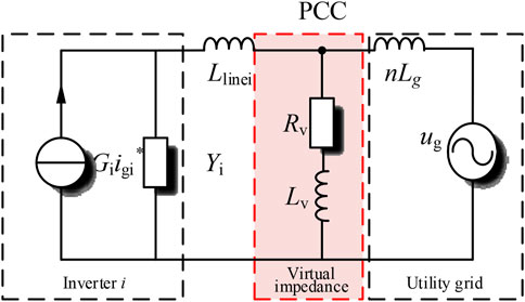
Hence, adding an active impedance can be approximately equivalent to parallel passive impedance at PCC, and the virtual impedance of resonance control is consistent with the size of passive impedance. The stability analysis of passive impedance can be approximately used to judge the influence of the active device on system stability and select the appropriate impedance. The circuit model of the multi-inverter parallel system with active impedance is drawn, as shown in Figure 11.
3.3 Stability Analysis
From the PCC point to the utility grid side, it is not difficult to find that the virtual impedance branch and the grid impedance nLg are in parallel. The total parallel impedance is defined as the equivalent power grid impedance Zg∗. By reasonably designing the parameters of Rv and Lv, so that Zg∗ and Zout meet the Nyquist stability criterion, the stable operation of the system can be ensured.
Taking Laplace transform for Eq. 13, the phase frequency characteristic expression of Zg∗ is calculated as follows:
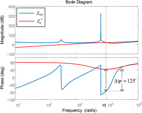
Through calculation and analysis of Eq. 14, it is found that the phase of Zg∗ reaches the lowest value in the frequency band near the angular frequency ωv. When it is higher or lower than this frequency band, the phase approaches 90°. It is consistent with the actual grid impedance. According to this characteristic, the parameters of virtual impedance are designed to make ωv in or close to the resonance instability region of Figure 5 which can reduce the phase difference between the grid impedance and the inverter output impedance, so as to reduce the system resonance risk. The expression of ωv is as follows:
The grid impedance Lg is 1 mH, Rv is 10 Ω, and Lv is 0.5 mH. Bode diagrams of inverter output impedance Zout and grid equivalent impedance Zg* are drawn, as shown in Figure 12.
It can be seen from Figure 12 that the parallel active impedance at PCC only changes the grid impedance characteristics in the resonance unstable region, while the grid impedance curves in the low-frequency band and high-frequency band are almost unchanged. The phase angle difference between the inverter output impedance Zout and the grid impedance Zg∗ at the intersection frequency is obviously less than 180°, meeting the Nyquist stability criterion. Therefore, the input of active impedance improves the system stability and effectively suppresses the resonance caused by the impedance coupling between the multi-inverter parallel system and weak grid.
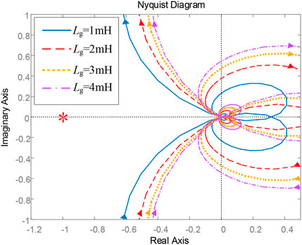
In the actual system, the grid impedance is not fixed but will fluctuate under the influence of various factors. The impedance ratio of the system containing active impedance is shown in Eq. 16. The Nyquist plot of Tm′ at different grid impedances is drawn, as shown in Figure 13.
It can be seen from Figure 13 that after the resonance suppression strategy based on active impedance is applied to the grid-connected system, the Nyquist curve of Tm′ does not surround (−1, j0) with the grid impedance increases from 1 mH to 4 mH. Hence, it can be determined that the system is stable. Therefore, the resonance suppression method proposed in this article can effectively improve the adaptability of inverters to weak grid and enhance the stability of the multi-inverter parallel system.
4 Simulation Results
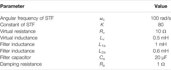
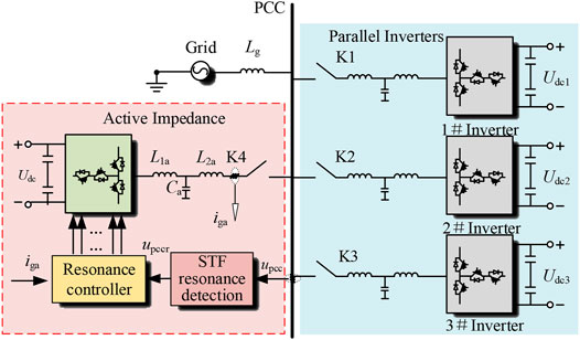
In order to verify the effectiveness of the resonance suppression strategy proposed in this article, the parallel system simulation model of active impedance based on the STF resonance extraction method and T-type three-level inverter are carried out in Simulink. The parameters of grid-connected inverter and active impedance are shown in Table 1 and Table 2, respectively. The overall block diagram of the system is shown in Figure 14.
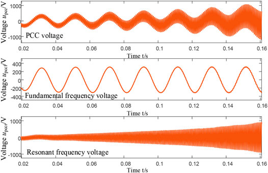
Considering the environment of weak grid, the simulated grid impedance Lg is 1mH, and the voltage at PCC of the multi-inverter parallel system is shown in Figure 15. Due to the coupling with weak grid, the system has harmonic resonance, and PCC voltage distortion is serious. In the figure, upccf and upccr are the fundamental voltage and resonance voltage waveforms separated by the resonance detection method based on STF, respectively. It can be seen from the figure that the separated fundamental voltage waveform is good and changes sinusoidally with an equal amplitude over time; the envelope of the resonant voltage component is clear and presents the divergent sinusoidal law. The simulation results show that by applying the resonance detection method proposed in this article to the sampled voltage, the fundamental frequency component of the voltage can be tracked without the static error, and the resonance component can be completely extracted.
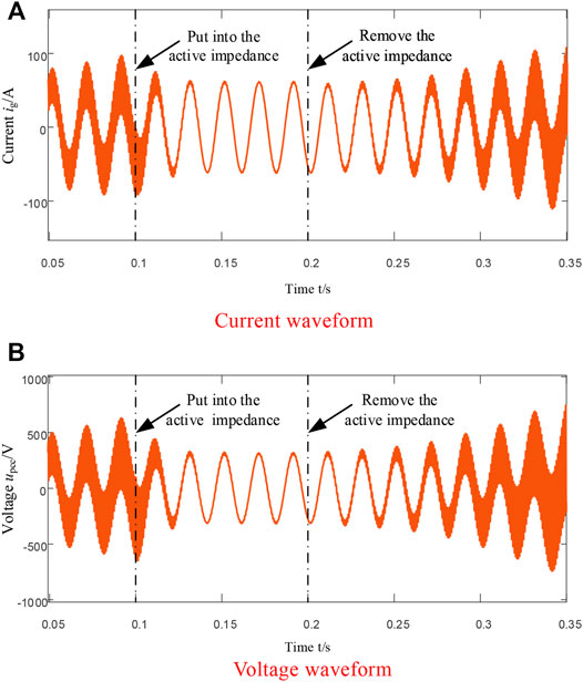
Figure 16 shows the waveform of the total grid-connected current and PCC voltage. It can be seen from the figure that before 0.1 s the resonance of the grid-connected system was unstable, the voltage and current were harmonic resonance amplified, and the grid-connected power quality decreased. Put into the active impedance at 0.1 s. After about one-cycle transition, the resonance in the system is eliminated, the sinusoidal degree of the voltage and current waveform becomes better, the grid-connected power quality is improved, and the system is gradually stable. When the active impedance is cut off again at 0.2 s, the system has harmonic resonance, the voltage and current waveform gradually oscillates and diverges, and the power quality gradually deteriorates.
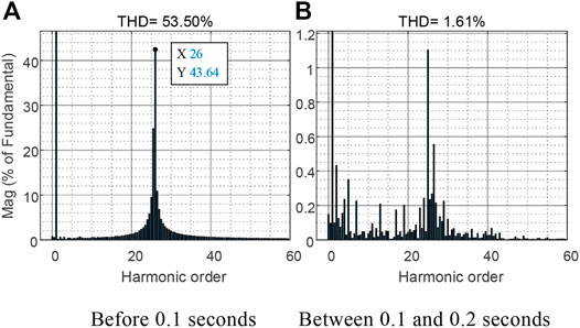
FFT harmonic analysis of the grid-connected current shall be carried out before 0.1 s, as shown in Figure 17A. At this time, the total harmonic distortion (THD) of the current reaches 53.50%, of which the 26th harmonic reaches 43.64%, indicating that the system has resonance at this frequency, which is the resonance peak generated by coupling with the weak grid. Figure 17B shows the harmonic analysis after the active impedance is put into operation. It can be seen from the figure that the harmonic of each order has been reduced below 1.2%, and the resonance has been suppressed. At this time, the distortion rate of the grid-connected current is 1.61%, which meets the grid-connected requirements.
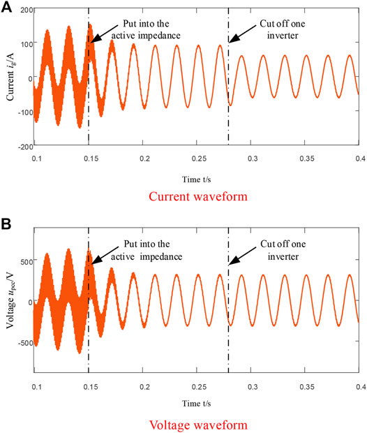
As shown in Figure 18, before 0.15 s, the grid-connected system resonated due to the coupling effect of grid impedance, and the voltage and current waveform was seriously distorted. When the active impedance is put at 0.15 s, the system gradually recovers to a stable state. When one inverter is cut off at 0.28 s, only the amplitude of the total grid-connected current in the system decreases, the PCC voltage waveform remains normal, the inverter can still maintain stable operation, and the system has good robustness.
Conduct harmonic analysis on the voltage and current of the multi-inverter parallel system under different grid impedance, and calculate the THD of the grid-connected current and PCC voltage after putting into the active impedance, as shown in Table 3. After adopting the resonance suppression method proposed in this article, the voltage and current distortion rate is not more than 5%, which meets the requirements of grid connection. The adaptability of inverters to weak grid is enhanced, and the simulation results are consistent with the theoretical analysis.
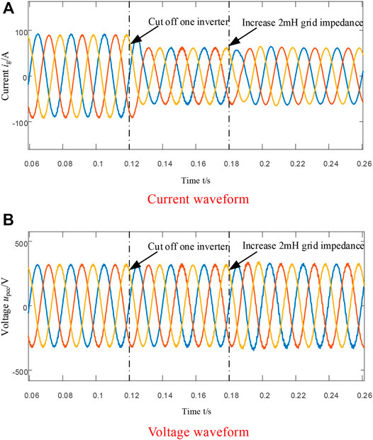
The voltage and current waveform of the grid-connected system with active impedance in the dynamic process is shown in Figure 19. One inverter is cut off at 0.12 s, and the grid impedance is increased form 1 mH–3 mH at 0.18 s. As shown, the total grid-connected current fluctuates only slightly during switching, and the current amplitude decreases rapidly to two-thirds of the original, and the system can still realize stable operation, and the grid-connected current will quickly return to a stable state after 0.18 s. PCC voltage can remain stable in the dynamic process of inverter switching and grid impedance fluctuation.
5 Conclusion
Aiming at the issue that resonance instability is easy to occur in parallel operation of multi-inverters under weak grid, active impedance and its resonance detection method are designed. The simulation results show that the resonance detection method based on STF proposed in this article can accurately extract the resonance voltage signal at PCC, and the design of the resonance detection module is simple and convenient for digital realization. The input of active impedance can improve the impedance characteristics of utility grid at resonance frequency, so as to reduce the resonance instability risk of the multi-inverter parallel system. Meanwhile, the resonance suppression method proposed in this article increases the safe and stable operation margin of the system, enhances the adaptability of the multi-inverter parallel system to the actual working conditions such as utility grid impedance fluctuation and inverter switching, and improves the system stability.
Data Availability Statement
The raw data supporting the conclusions of this article will be made available by the authors, without undue reservation, to any qualified researcher. Requests to access the datasets should be directed to TZ, emRoeHp0QG5qaXQubmV0LmNu.
Author Contributions
TZ contributed to the conception and design of the proposed strategy. All authors wrote and edited the manuscript.
Funding
This work was supported by the National Natural Science Foundation of China (61901212).
Conflict of Interest
The authors declare that the research was conducted in the absence of any commercial or financial relationships that could be construed as a potential conflict of interest.
Publisher’s Note
All claims expressed in this article are solely those of the authors and do not necessarily represent those of their affiliated organizations, or those of the publisher, the editors, and the reviewers. Any product that may be evaluated in this article, or claim that may be made by its manufacturer, is not guaranteed or endorsed by the publisher.
References
Agorreta, J. L., Borrega, M., López, J., and Marroyo, L. (2011). Modeling and Control of $N$ -Paralleled Grid-Connected Inverters with LCL Filter Coupled Due to Grid Impedance in PV Plants. IEEE Trans. Power Electron. 26 (3), 770–785. March 2011. doi:10.1109/TPEL.2010.2095429
Akhavan, A., Vasquez, J. C., and Guerrero, J. M. (2021). A Robust Method for Controlling Grid-Connected Inverters in Weak Grids. IEEE Trans. Circuits Syst.68 (4), 1333–1337. doi:10.1109/TCSII.2020.3033427
Biricik, S., Redif, S., Özerdem, Ö. C., Khadem, S. K., and Basu, M. (2014). Real‐time Control of Shunt Active Power Filter under Distorted Grid Voltage and Unbalanced Load Condition Using Self‐tuning Filter. Iet Power Electron. 7 (7), 1895–1905. doi:10.1049/iet-pel.2013.0924
Chen, D., Zhang, J., and Qian, l. (2013). Single Current Feedback Control Strategy of Grid-Connected Inverters with LCL Filters. Proc. CSEE 33 (9), 10–16.
Fang, T., Shen, S., Jin, Y., and Ruan, X. (2021). Robustness Investigation of Multi-Inverter Paralleled Grid-Connected System with LCL-Filter Based on the Grid-Impedance Allocation Mechanism. IEEE Trans. Power Electron. 36 (12), 14508–14524. Dec. 2021. doi:10.1109/TPEL.2021.3088992
Gao, J., Tu, C., Guo, Q., Xiao, F., Jiang, F., and Lu, B. (2020). “Impedance Reshaping Control Method to Improve Weak Grid Stability of Grid-Connected Inverters, in” ECON 2020 The 46th Annual Conference of the IEEE Industrial Electronics Society, Singapore, October 18–21, 2020, 1342–1346. doi:10.1109/IECON43393.2020.9254917
Hong, L., Shu, W., Wang, J., and Mian, R. (2019). Harmonic Resonance Investigation of a Multi-Inverter Grid-Connected System Using Resonance Modal Analysis. IEEE Trans. Power Deliv. 34 (1), 63–72. Feb. 2019. doi:10.1109/TPWRD.2018.2877966
Hu, W., Zhou, H., Sun, J., Jiang, Y., and Zha, X. (2015). Resonance Analysis and Suppression of System with Multiple Grid-Connected Inverters, in” 2015 IEEE 2nd International Future Energy Electronics Conference (IFEEC), Taipei, Taiwan, November 1–4, 2015. doi:10.1109/IFEEC.2015.7361517
Kang, H. (2020). Research on Resonance Instability Suppression Strategy for Multi-Inverter Grid-Connected System Based on Reshaping of Global Admittance at PCC. Nanjing, China: Southeast University.
Natori, K., Ishikawa, A., and Sato, Y. (2020). A Study on Resonance Suppression Control Based on Virtual Resistance Concept for Parallel Inverters in Islanded Microgrid, in” 2020 IEEE 9th International Power Electronics and Motion Control Conference (IPEMC2020-ECCE Asia), Nanjing, China, November 29–December 2, 2020. doi:10.1109/IPEMC-ECCEAsia48364.2020.9367851
Lu, M., Yang, Y., Johnson, B., and Blaabjerg, F. (2019). An Interaction-Admittance Model for Multi-Inverter Grid-Connected Systems. IEEE Trans. Power Electron. 34 (8), 7542–7557. Aug. 2019. doi:10.1109/TPEL.2018.2881139
Pan, D., Ruan, X., Bao, C., Li, W., and Wang, X. (2014). Capacitor-Current-Feedback Active Damping with Reduced Computation Delay for Improving Robustness of LCL-type Grid-Connected Inverter. IEEE Trans. Power Electron. 29 (7), 3414–3427. doi:10.1109/TPEL.2013.2279206
Sun, J. (2011). Impedance-Based Stability Criterion for Grid-Connected Inverters. IEEE Trans. Power Electron. 26 (11), 3075–3078. Nov. 2011. doi:10.1109/TPEL.2011.2136439
Zhen-Ao, S., Zi-Long, Y., Yi-Bo, W., and Hong-Hua, X.. (2014). Analysis of Harmonic Resonances Among Parallel Grid-Connected Inverters, in” 2014 International Conference on Power System Technology, Chengdu, China, October 20–22, 2014. doi:10.1109/POWERCON.2014.6993560
Wan, Q., Zhang, H., Zhang, X., and Sun, J. (2018). Research on Resonance Mechanism and Suppression Technology of Photovoltaic Cluster Inverter. Power Syst. Tech. 42 (10), 3377–3384. doi:10.3390/en11040938
Wang, X., Pang, Y., Loh, P. C., and Blaabjerg, F. (2015). A Series-LC-Filtered Active Damper with Grid Disturbance Rejection for AC Power-Electronics-Based Power Systems. IEEE Trans. Power Electron. 30 (8), 4037–4041. doi:10.1109/TPEL.2014.2382477
Xiong, L., Liu, X., and Liu, Y. (2021). Decaying DC and Harmonic Components Detection for Absorbing Impact Load Currents in Weak Grids. IEEE Trans. Power Deliv. 36 (3), 1907–1910. June 2021. doi:10.1109/TPWRD.2020.3038077
Xiong, L., Liu, X., Liu, Y., and Zhuo, F. (2020). Modeling and Stability Issues of Voltage-Source Converter Dominated Power Systems: A Review. Csee Jpes. doi:10.17775/CSEEJPES.2020.03590
Xu, C. (2019). Research on Control System for Single-phase Grid-Connected Inverter with LCL Filter. Zhenjiang, China: Jiangsu University.
Yang, D., Ruan, X., and Wu, H. (2014). Impedance Shaping of the Grid-Connected Inverter with LCL Filter to Improve its Adaptability to the Weak Grid Condition. IEEE Trans. Power Electron. 29 (11), 5795–5805. Nov. 2014. doi:10.1109/TPEL.2014.2300235
Yu, C., Xu, H., Liu, C., Wang, Q., and Zhang, X. (2019). Modeling and Analysis of Common-Mode Resonance in Multi-Parallel PV String Inverters. IEEE Trans. Energ. Convers. 34 (1), 446–454. March 2019. doi:10.1109/TEC.2018.2877911
Zeng, J., Zhang, Z., and Qiao, W. (2014). An Interconnection and Damping Assignment Passivity-Based Controller for a DC-DC Boost Converter with a Constant Power Load. IEEE Trans. Ind. Applicat. 50 (4), 2314–2322. July-Aug. 2014. doi:10.1109/TIA.2013.2290872
Keywords: resonance, parallel inverters, LCL filter, weak grid, active impedance
Citation: Zhao T, Cao Y, Zhang M, Wang C and Sun Q (2022) Research on the Resonance Suppression Method for Parallel Grid-Connected Inverters Based on Active Impedance. Front. Energy Res. 9:823746. doi: 10.3389/fenrg.2021.823746
Received: 28 November 2021; Accepted: 20 December 2021;
Published: 20 January 2022.
Edited by:
Weihao Hu, University of Electronic Science and Technology of China, ChinaReviewed by:
Xiaokang Liu, Politecnico di Milano, ItalyYouyuan Ni, Hefei University of Technology, China
Copyright © 2022 Zhao, Cao, Zhang, Wang and Sun. This is an open-access article distributed under the terms of the Creative Commons Attribution License (CC BY). The use, distribution or reproduction in other forums is permitted, provided the original author(s) and the copyright owner(s) are credited and that the original publication in this journal is cited, in accordance with accepted academic practice. No use, distribution or reproduction is permitted which does not comply with these terms.
*Correspondence: Tao Zhao, emRoeHp0QG5qaXQubmV0LmNu
 Tao Zhao*
 Yunkai Cao

