- 1Institute of Nuclear and New Energy Technology, Advanced Nuclear Energy Technology Cooperation Innovation Center, Key Laboratory of Advanced Nuclear Engineering and Safety, Ministry of Education, Tsinghua University, Beijing, China
- 2Tsinghua University-Zhang Jiagang Joint Institute for Hydrogen Energy and Lithium-Ion Battery Technology, Tsinghua University, Beijing, China
Owing to the current serious environmental and climate problems, the energy industry must focus on the problem of energy utilization rates. High-temperature gas-cooled reactors (HTGRs) are fourth-generation reactors, characterized by high outlet temperatures. The combined cycle is composed of the gas turbine and steam turbine cycles, and it can realize the cascade utilization of high-quality energy. It is a highly competitive power conversion scheme for HTGRs. In this study, the matching characteristics of the combined cycle coupled with HTGRs are revealed through the progressive optimization method. In the combined cycle coupled with HTGRs, the topping and bottoming cycle are both closed cycles, therefore, the optimization for cycle efficiency is to match the topping and bottoming cycles. For a combined cycle with subcritical steam parameters, there are two extreme values of the combined cycle efficiency that have different power ratios. The characteristics revealed in this study are unique to closed combined cycle coupled with HTGRs.
Introduction
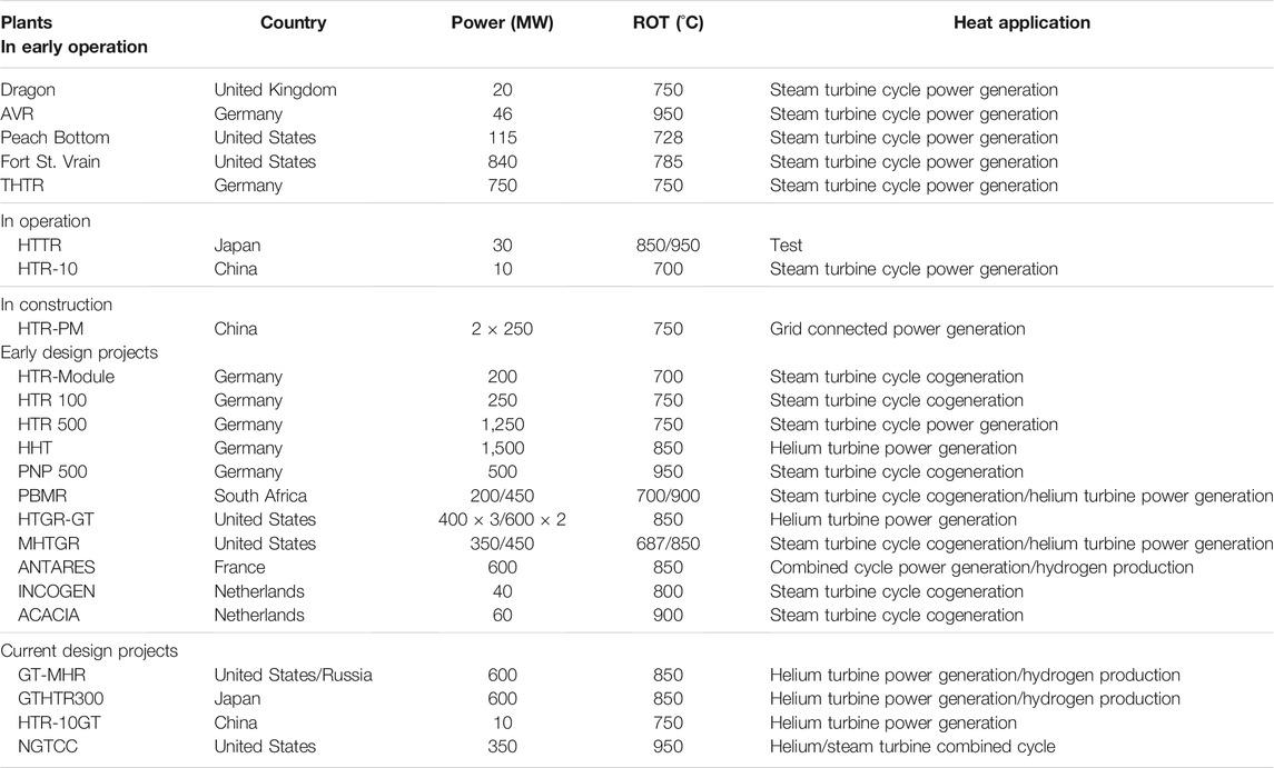
High-temperature gas-cooled reactors (HTGRs) have experienced a long and tortuous development since the middle of the previous century. The final technical route focuses on small modular HTGRs with inherent safety (Kugeler et al., 2019). HTGRs use helium as the cooling medium, and its reactor outlet temperature (ROT) can reach 700–950 C (shown in Table 1). Compared with HTGRs, the outlet temperature of very-high-temperature gas-cooled reactors (VHTRs) is higher and can exceed 1,000 C. In addition, it can realize a wide range of applications, including the combined cycle and nuclear hydrogen production (Sun et al., 2020; International Atomic Energy Agency, 2012).
There are two types of power generation systems for HTGRs: the steam turbine cycle power generation system and helium turbine cycle power generation system. The HTGR projects that use the steam cycle for the power generation system are listed in Table 1 (Simnad, 1991; Frutschi, 2005; McDonald, 2012; Olumayegun et al., 2016). These mainly include the Dragon in the United Kingdom and the AVR in Germany, which started operation as early as the 1960s; the HTTR in Japan and the HTR-10 in China, which are currently in operation; and the demonstration reactor HTR-PM in China, which is currently under construction. The HTGR design projects that use a helium turbine as the power generation system mainly include the GTHTR300 in Japan, the HTGR-GT (Bardia, 1980; McDonald et al., 1981) in the United States, the GT-MHR in the United States and Russia cooperation, the HTR-10GT in China, and the PBMR in South Africa.
The theoretical basis of the steam turbine cycle power generation system is the Rankine cycle. Its cycle efficiency increases with an increase in the pressure and temperature of the main steam. Theoretically, the maximum temperature of the main steam can reach 500 C or even 600°C; however, the temperature difference between the main steam and helium from the reactor outlet is large for HTGRs, and the loss of work capacity is large.
Because the pressure vessel of the steam generator in HTGRs is not suitable for penetration by the reheating steam pipeline, the pressure of the main steam cannot be too high, and it is suitable for subcritical pressure (Zhang et al., 2006; Zhang et al., 2009). Therefore, the technical scheme for the steam turbine cycle power generation cannot provide the full high-temperature advantage of HTGRs.
The efficiency of the helium turbine power generation mainly depends on the gas temperature at the turbine inlet; it increases with an increase in the gas temperature. For the blade without cooling, the inlet temperature of the helium turbine can reach 850°C; for the blade with cooling, the temperature can exceed 1,000 C (Baxi et al., 2008; McDonald, 2014). Therefore, the technical solution for helium turbine power generation is to make full use of the high-grade heat source of HTGRs, thereby providing the high-temperature advantages of HTGRs. This is suitable for the future power generation program of VHTRs.
There are two types of helium turbine power generation: the direct turbine cycle and combined cycle. The direct helium turbine cycle usually adopts the Brayton cycle with precooling, intercooling, and recuperating (Baxi et al., 2008; Wang et al., 2004; Wang et al., 2018). For the direct helium turbine cycle, when the ROT is high, the reactor inlet temperature is also high owing to recuperation. This is limited by the material of the reactor pressure vessel (RPV), and the inner wall of the RPV should be cooled, which increases the system complexity (Kim et al., 2006; Natesan et al., 2007; Demick, 2012). The combined cycle, in which the topping cycle is the simple Brayton cycle, can make maximal use of the high-grade heat from HTGRs; the RPV in this case is not limited by the materials. Research on the combined cycle coupled with HTGRs (CC-HTGRs) is represented by the ANTARES (Gauthier et al., 2006; Gomez et al., 2010) in France and the NGTCC (McDonald, 2014 and 2010) in the United States.
The CC-HTGRs have the same principle as the gas–steam combined cycle (Duan, 2010). This is a cycle form that is based on the principle of energy cascade utilization (Jin, 2008); however, the two are significantly different. The main differences are as follows:
(1) The topping cycle of CC-HTGRs is a closed cycle, and its minimum cycle temperature is affected by the bottoming cycle.
(2) The heat recovery steam generator (HRSG) in CC-HTGRs is a once-through steam generator, including the preheating section, evaporation section, and superheating section, but excluding the steam drum.
(3) Because the heat source of CC-HTGRs is the reactor, some cycle parameters (such as reactor inlet temperature and compression ratio) need to meet certain constraints (Qu et al., 2020).
Presently, there are a limited number of studies that focus on CC-HTGRs, which are far from adequate. McDonald (2010) and McDonald (2014) proposed a combined cycle scheme coupled with an HTGR with a ROT of 950 C to generate power and provide district heating. The thermal power of the reactor is 350 MW, the power distribution is 50 MW in the topping cycle and 130 MW in the bottoming cycle, and the plant efficiency can reach 51.5%. Gomez et al. (2009) and Gomez et al. (2010) conducted optimization studies on the CC-HTGRs, which mainly focused on the optimization method, and research on the system characteristics that were lacking. Jaszczur et al. (2018) and Jaszczur et al. (2020) carried out thermodynamic analyses and compared the characteristics of CC-HTGRs coupled with single-pressure, double-pressure, three-pressure, interstage superheating, and reheating HRSGs. The authors and their research team of this study conducted studies on CC-HTGRs, including comparisons of the different cycle schemes (Wang et al., 2015; Wang et al., 2016), cycle characteristic analyses (Chen, 2001), cycle optimization (Yang et al., 2020), and off-design performance analysis (Qu et al., 2019).
Before this study, the authors used a genetic algorithm to optimize the combined cycle efficiency of a CC-HTGR model and found that the optimal value alternated between two groups of parameters, which did not conform to the expected trend, the authors used a genetic algorithm to optimize the combined cycle efficiency of a CC-HTGR model and found that the optimal value alternated between two groups of parameters, which did not conform to the expected trend. To further explore the internal reasons, the authors chose the most basic CC-HTGR model to perform this research and reveal the reasons of the above discrepancy.
Calculation Model and Method
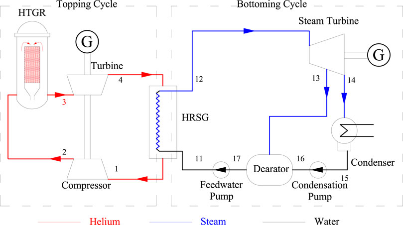
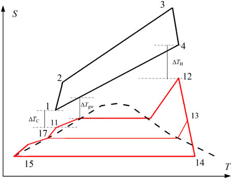
According to the authors' previous analysis, the CC-HTGR comprising a simple Brayton cycle and a reheating and multistage regenerative Rankine cycle is more competitive (Chen, 2001; Jin et al., 2008). Because this article is a theoretical study on the characteristics of the CC-HTGRs and the purpose is to reveal the internal relationship between the cycle parameters, the bottoming cycle is simplified and the combined cycle shown in Figure 1 is used as the analysis model, and no control components are added. This study is based on the cycle model shown in Figure 1. Figure 2 is the corresponding temperature–entropy diagram. The combined cycle consists of the topping cycle, bottoming cycle, and HRSG. The topping cycle in Figure 1 is a simple Brayton cycle. After the helium is heated in the reactor (2–3), it directly enters the helium turbine for expansion (3–4). The temperature of the expanded helium is still high. It enters the HRSG to transfer the heat to the feed water (4–1) of the bottoming cycle. After the heat is released, the helium enters the compressor so it can be compressed (1–2), and then it returns to the reactor to complete the cycle.
The bottoming cycle in Figure 1 is a subcritical Rankine cycle without reheat, which contains one stage of regeneration (the deaerator). The feed water absorbs the heat (11–12) in the HRSG to reach an overheated state, and then it enters the steam turbine to expand (12–14). The exhaust steam from the steam turbine is condensed into saturated water in the condenser. Then, it successively flows through the condensation pump, deaerator, and feed water pump. After these processes, the feed water returns to the HRSG. The heat source of the deaerator is extracted from the steam turbine.
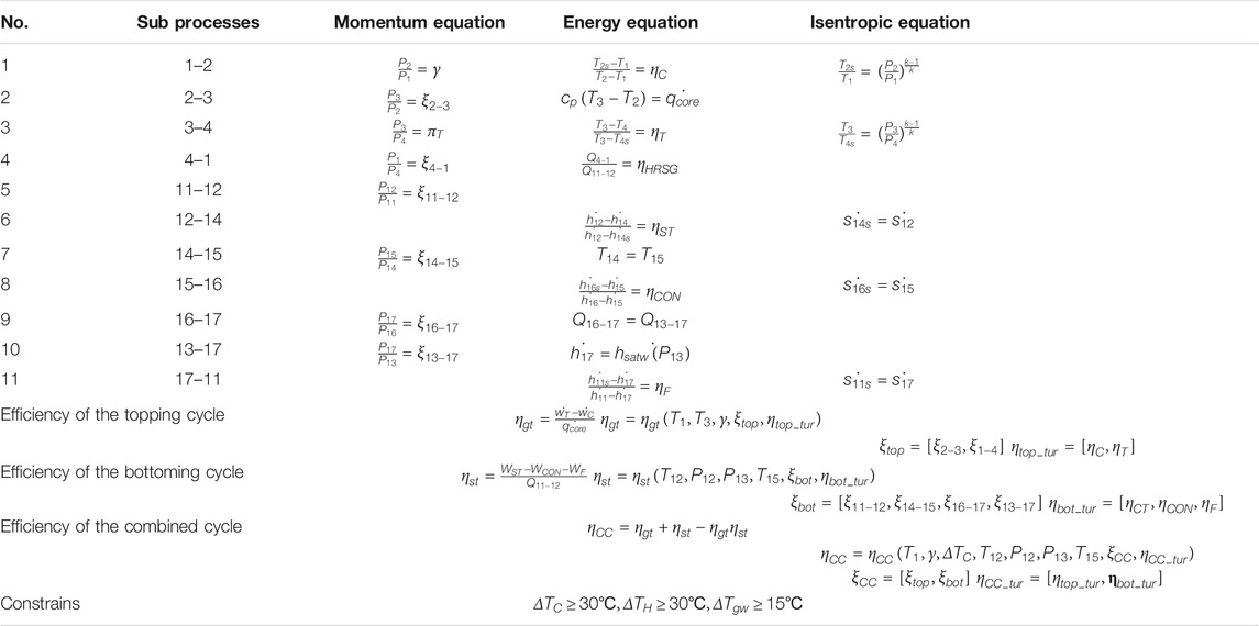
The thermodynamic model of the CC-HTGR is presented in Table 2, which includes the momentum, energy, and isentropic equations of the 11 subprocesses.
Assumptions and calculation conditions used in this study:
1) For steady-state analysis, the resistance recovery coefficient, ξcc,, and isentropic efficiency, ηcc_tur, of the components in the cycle were not used as the analysis variables, and their values are as follows:
2) The condensation temperature, T15, depends on the environmental conditions and was not used as the analysis variable, and its value is 33 C (P15 = 5 kPa).
3) According to a previous analysis (Yang et al., 2020), the ROT, T3, is a monotonically increasing function of the combined cycle efficiency; therefore, T3 was not used as the analysis variable. Only the ROT of 950 C was considered.
4) Similarly, the main steam pressure, P12, is also a monotonically increasing function of the combined cycle efficiency, and P12 was not used as the main analysis variable. The subcritical steam pressures of 16, 18, and 20 MPa were analyzed and compared.
Under the above conditions, the combined cycle efficiency can be expressed as follows:
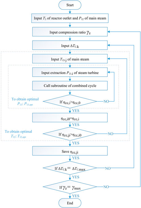
The calculation and analysis methods are shown in Figure 3. The calculation includes four levels: the first level searched for the best extraction pressure, P13; the second level searched for the best main steam temperature, T12; the third level observed the influence of the temperature difference at the cold end of HRSG, ΔTC, on cycle efficiency; and the forth level observed the influence of the compression ratio, γ, on cycle efficiency.
Result Analysis
First Level Optimization
According to the analysis method shown in Figure 3, the extraction pressure, P13, and main steam temperature, T12, are optimized. The combined cycle efficiency shown in Eq. 1 can be expressed as follows:
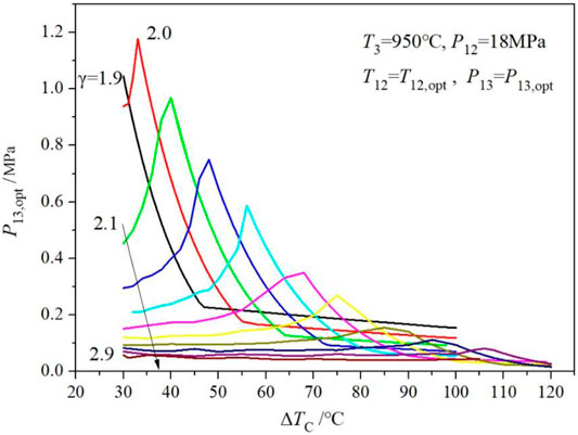
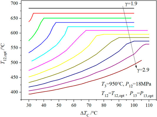
The effects of the other two parameters (ΔTC and γ) on the combined cycle efficiency are presented in Figure 3. Figure 5 shows the optimized value of steam turbine extraction pressure, P13,opt, corresponding to Figure 4. Figure 6 indicates the optimized value of the main steam temperature, T12,opt, corresponding to Figure 4.
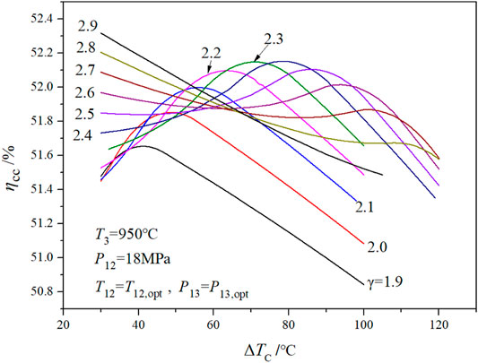
FIGURE 4. Relationship curves of combined cycle efficiency with cold end temperature difference and compression ratio.
When the compression ratio changes from 1.9 to 2.9, the combined cycle efficiency shows one extreme point, then two extreme points, and finally one extreme point (as shown in Figure 4). During the change of the compression ratio, the optimal value of the main steam temperature, T12,opt, gradually decreases; it also varies with the temperature difference at the cold end, ΔTC (as shown in Figure 6). When ΔTC is large, T12,opt is at the maximum point of the main steam temperature (that is, the minimum point of the temperature difference at the hot end ΔTH); when ΔTC is small, T12,opt decreases (ΔTH increases accordingly). T12,opt also affects the optimized value of the steam turbine extraction pressure, P12,opt (as shown in Figure 5). When the compression ratio increases from 1.9 to 2.0, P12,opt decreases gradually. When ΔTC increases, P12,opt increases first, then decreases, and finally reaches an optimal value.
Furthermore, the interval between two extreme points (γ = 2.5–2.7), shown in Figure 4, was calculated. The results are shown in Figure 7 and Table 3. When the compression ratio is 2.5, the extreme value of cycle efficiency on the right side of Figure 7 is greater than that on the left side. When the compression ratio is 2.7, the extreme value of the left side is greater than that of the right side. When the compression ratio is 2.62 (as shown in bold in Table 3), the extreme values of the two cycle efficiencies are equal, the corresponding ΔTC values are 30°C and 95°C, and the optimized main steam temperatures are 430°C and 582°C, respectively.
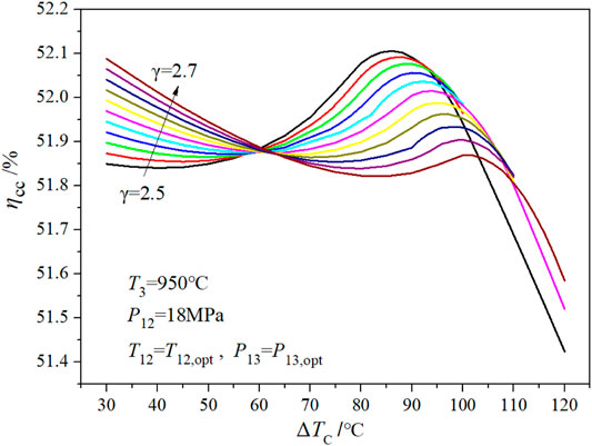
FIGURE 7. Relationship between combined cycle efficiency and cold end temperature difference in the local compression ratio range.
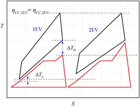
Figure 8 further reveals the difference between the temperature–entropy diagrams of the combined cycle under two extreme conditions. The essence of efficiency optimization for CC-HTGRs is to match the topping cycle with the bottoming cycle. In Figure 8, the area of the topping cycle at the first extreme point is larger than that at the second extreme point; by contrast, the area of the bottoming cycle at the first extreme point is smaller than that at the second extreme point. A variable called the power ratio (PR) is defined to reflect the matching characteristics of the topping cycle and the bottoming cycle in the combined cycle. The PR is defined as the ratio of the output power of the topping cycle to the total output power of the combined cycle, as shown in Eq. 2. The PR at the first extreme point is 0.388, and at the second extreme point is 0.330.
Second Level Optimization
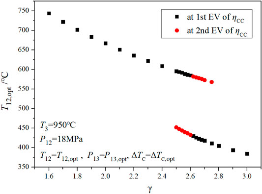
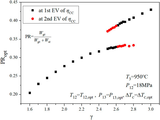
Based on Eq. 3, the expression of the combined cycle efficiency shown in Eq. 4 can be obtained by further optimizing ΔTC. The extreme values of cycle efficiency, corresponding main steam temperatures, and PRs at different compression ratios were extracted, and the results are shown in Figures 9–11, and Figure 9. shows that as the compression ratio increases, the main steam temperature corresponding to the extreme point of cycle efficiency decreases. It is clear that there are two extreme values (EVs) in a given compression ratio range (the first EV in the figures is the maximum value of cycle efficiency). As the compression ratio increases, the PR increases; that is, the proportion of the output power from the topping cycle increases.
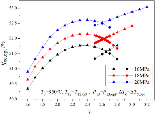
The main steam pressures of 16, 18, and 20 MPa are shown in Figure 11 to compare and verify the conclusions. The calculation results of the three main steam pressures shown in the figure are consistent. For each main steam pressure, curve γ-ηCC,opt consists of two different curves. The two curves intersect at a compression ratio, γE. Near the intersection point, γE, a compression ratio corresponds to two ηCC,opt, which is the result of the first step optimization. The results of the second step optimization can be obtained by extracting the upper half part of the two γ-ηCC,opt curves. The left half of the new curve is approximately parabolic, and the right half is approximately linear. Therefore, there are still two extreme points of cycle efficiency. The compression ratio corresponding to the two extreme values are 2.3 and 3.0, and the PRs are 0.31 and 0.43, respectively. In the engineering design, the compression ratio is limited by the engineering conditions, generally less than 3.0; therefore, there are two optimization points for the cycle efficiency of CC-HTGR.
Conclusion
Facing the current climate problem, nuclear energy can play a big role. High-temperature gas-cooled reactor is a new generation of inherent safety reactor with great potential, which is characterized by high temperature. The world’s first HTGR demonstration plant (HTR-PM) has reached the critical point and connected to the grid for power generation in China. The next development will further improve the reactor outlet temperature. When the reactor outlet temperature is high, the steam cycle cannot fully show the advantages of the high-temperature reactor, and the combined cycle is a highly competitive power conversion scheme for HTGRs. Because the topping cycle and bottoming cycle are closed cycles, the combined cycle coupled with HTGRs has some characteristics different from the conventional combined cycle. In this study, the matching characteristics of the topping and bottoming cycles of the combined cycle coupled with HTGRs under subcritical steam parameters were studied. The derived thermodynamic model showed that the combined cycle efficiency has four main optimization variables: compression ratio, temperature difference at the cold end, main steam temperature, and steam turbine extraction pressure. Based on a progressive optimization method, the steam turbine extraction pressure and main steam temperature were first analyzed and optimized. After the temperature difference at the cold end was analyzed in the second level optimization, the compression ratio–cycle efficiency curve was obtained. The compression ratio–cycle efficiency curve consists of two curves with different shapes, which makes the combined cycle efficiency have two extreme values in the domain of definition. In CC-HTGRs, the topping and bottoming cycles are both closed cycles; therefore, the optimization for the combined cycle efficiency is to match the topping and bottoming cycles. The optimization of the combined cycle efficiency is to maximize the area of the topping and bottoming cycles in the temperature–entropy diagram, which is to optimize the cycle PR. Under the reactor outlet temperature of 950°C and main steam pressure of 18 MPa, the compression ratios of the two extreme values are 2.3 and 3.0, and the PRs are 0.31 and 0.43, respectively. This study is helpful to understand the CC-HTGR and improve the energy efficiency.
Data Availability Statement
The raw data supporting the conclusions of this article will be made available by the authors, without undue reservation.
Author Contributions
XQ is the main finisher of the manuscript. XY provided guidance and suggestions for the overall thinking of the manuscript. JW provided guidance and suggestions for the thermodynamic model of the manuscript.
Funding
This work was supported by the National Key R&D Program of China (Grant No. 2018YFB1900500), the National Science and Technology Major Project (Grant No. ZX069), and the Youth Talent Project of China National Nuclear Corporation.
Conflict of Interest
This study received funding from China National Nuclear Corporation. The funder was not involved in the study design, collection, analysis, interpretation of data, the writing of this article, or the decision to submit it for publication.
The authors declare that the research was conducted in the absence of any commercial or financial relationships that could be construed as a potential conflict of interest.
Publisher’s Note
All claims expressed in this article are solely those of the authors and do not necessarily represent those of their affiliated organizations, or those of the publisher, the editors, and the reviewers. Any product that may be evaluated in this article, or claim that may be made by its manufacturer, is not guaranteed or endorsed by the publisher.
References
Bardia, A. (1980). Dynamics and Control Modeling of the Closed-Cycle Gas Turbine (GT-HTGR) Power Plant. California: General Atomic Co. GA-A 15677.
Baxi, C. B., Shenoy, A., Kostin, V. I., Kodochigov, N. G., Vasyaev, A. V., Belov, S. E., et al. (2008). Evaluation of Alternate Power Conversion Unit Designs for the GT-MHR. Nucl. Eng. Des. 238, 2995–3001. doi:10.1016/j.nucengdes.2007.12.021
Chen, Y. H. (2001). Study on Potentiality of High Temperature Gas-Cooled Reactor-Combined Cycle System. Nucl. Power Eng. 22, 475–480.
Demick, L. (2012). Using SA508/533 for the HTGR Vessel Material. Idaho: Idaho National Laboratory (INL.
Duan, Q. S. (2010). Theory and Calculation of thermal Performance Analysis of Gas-Steam Combined Cycle Power Plant. Beijing: Tsinghua Univ. Press.
Frutschi, H. U. (2005). Closed-cycle Gas Turbines: Operating Experience and Future Potential. New York: ASME Press.
Gauthier, J.-C., Brinkmann, G., Copsey, B., and Lecomte, M. (2006). ANTARES: The HTR/VHTR Project at Framatome ANP. Nucl. Eng. Des. 236, 526–533. doi:10.1016/j.nucengdes.2005.10.030
Gomez, A., Azzaro-Pantel, C., Pibouleau, L., Domenech, S., Latgé, C., Dumaz, P., et al. (2009). A MultiObjective Genetic Algorithm Framework for Electricity/Hydrogen Co-production from Generation IV Nuclear Energy Systems. Comput.-Aided Chem. Eng. 26, 1263–1268. doi:10.1016/s1570-7946(09)70210-x
Gomez, A., Pibouleau, L., Azzaro-Pantel, C., Domenech, S., Latgé, C., and Haubensack, D. (2010). Multiobjective Genetic Algorithm Strategies for Electricity Production from Generation IV Nuclear Technology. Energ. Convers. Manag. 51, 859–871. doi:10.1016/j.enconman.2009.11.022
International Atomic Energy Agency (2012). Hydrogen Production Using Nuclear Energy. Vienna: Nuclear Energy Series.
Jaszczur, M., Dudek, M., and Kolenda, Z. (2020). Thermodynamic Analysis of Advanced Gas Turbine Combined Cycle Integration with a High-Temperature Nuclear Reactor and Cogeneration Unit. Energies 13, 400. doi:10.3390/en13020400
Jaszczur, M., Dudek, M., Śliwa, T., and Kolenda, Z. (2018). An Analysis of High-Temperature Nuclear Reactor Coupled with Gas Turbine Combined Cycle. MATEC Web Conf. 240, 05010. doi:10.1051/matecconf/201824005010
Jin, H. G., and Lin, N. M. (2008). Comprehensive cascade Utilization of Energy and Total Energy System of Gas Turbine. Beijing: Science press.
Kim, M. H., and Lee, W. J. (2006). “Survey on Cooled-Vessel Designs in High Temperature Gas-Cooled Reactors,” in Transactions of the Korean Nuclear Society Autumn Meeting Gyeongju.
Kugeler, K., and Zhang, X. Y. (2019). Modular High-Temperature Gas-Cooled Reactor Power Plant. Berlin. Springer.
McDonald, C. F. (2012). Helium Turbomachinery Operating Experience from Gas Turbine Power Plants and Test Facilities. Appl. Therm. Eng. 44, 108–142. doi:10.1016/j.applthermaleng.2012.02.041
McDonald, C. F. (2014). Power Conversion System Considerations for a High Efficiency Small Modular Nuclear Gas Turbine Combined Cycle Power Plant Concept (NGTCC). Appl. Therm. Eng. 73, 82–103. doi:10.1016/j.applthermaleng.2014.07.011
McDonald, C. F., and Smith, M. J. (1981). Turbomachinery Design Considerations for the Nuclear HTGR-GT Power Plant. South Windsor: General Atomic Co. GA-A 15614.
McDonald, C. G. (2010). Power Conversion System Considerations for an Advanced Nuclear Gas Turbine (GT-VHTR) CHHP Demonstration Plant Concept. Int. J. Turbo Jet Engines 27, 179–217. doi:10.1515/tjj.2010.27.3-4.179
Natesan, K., Majumdar, S., Shankar, P. S., and Shah, V. N. (2007). Preliminary Materials Selection Issues for the Next Generation Nuclear Plant Reactor Pressure Vessel. Oak Ridge: Argonne National Laboratory.
Olumayegun, O., Wang, M., and Kelsall, G. (2016). Closed-cycle Gas Turbine for Power Generation: A State-Of-The-Art Review. Fuel 180, 694–717. doi:10.1016/j.fuel.2016.04.074
Qu, X. H., Yang, X. Y., and Wang, J. (2020). Combined Cycles-Coupled High-Temperature and Very High-Temperature Gas-Cooled Reactors: Part II–Engineering Design. Ann. Nucl. Energy. doi:10.1016/j.anucene.2019.106953
Qu, X., Yang, X., and Wang, J. (2019). Off-design Performance and Power-Control Strategy for Combined Cycle Coupled with High-Temperature Gas-Cooled Reactor. Ann. Nucl. Energ. 130, 338–346. doi:10.1016/j.anucene.2019.03.009
Simnad, M. T. (1991). The Early History of High-Temperature Helium Gas-Cooled Nuclear Power Reactors. Energy 16, 25–32. doi:10.1016/0360-5442(91)90084-Y
Sun, Q., Gao, Q., Zhang, P., Peng, W., and Chen, S. (2020). Modeling Sulfuric Acid Decomposition in a Bayonet Heat Exchanger in the Iodine-Sulfur Cycle for Hydrogen Production. Appl. Energ. 277, 115611. doi:10.1016/j.apenergy.2020.115611
Wang, J., Cao, X., Meng, Z., and Ding, M. (2018). A Hybrid Semi-implicit Method of 1D Transient Compressible Flow for thermal-hydraulic Analysis of (V) HTR Gas Turbine Systems. Front. Energ. Res. 6, 1–11. doi:10.3389/fenrg.2018.00044
Wang, J., Ding, M., Yang, X. Y., and Wang, J. (2016). Performance Comparison and Optimization of Two Configurations of (Very) High Temperature Gas-Cooled Reactors Combined Cycles. Ann. Nucl. Energ. 94, 279–287. doi:10.1016/j.anucene.2016.03.009
Wang, J., Ding, M., Yang, X. Y., and Wang, J. (2015). Study on Compound Combined Cycle of High Temperature Gas-Cooled Reactor. At. Energ. Sci. Technol. 49, 616–622.
Wang, J., Huang, Z. Y., Zhu, S. T., and Yu, S. Y. (2004). “Design Features of Gas Turbine Power Conversion System for HTR-10GT,” in 2nd International Topical Meeting on High Temperature Reactor Technology.
Yang, X. Y., Qu, X. H., and Wang, J. (2020). Combined Cycle-Coupled High-Temperature and Very High-Temperature Gas-Cooled Reactors: Part I—Cycle Optimization. Ann. Nucl. Energ. 134, 193–204. doi:10.1016/j.anucene.2019.06.018
Zhang, Z., Wu, Z., Sun, Y., and Li, F. (2006). Design Aspects of the Chinese Modular High-Temperature Gas-Cooled Reactor HTR-PM. Nucl. Eng. Des. 236, 485–490. doi:10.1016/j.nucengdes.2005.11.024
Zhang, Z., Wu, Z., Wang, D., Xu, Y., Sun, Y., Li, F., et al. (2009). Current Status and Technical Description of Chinese 2×250MWth HTR-PM Demonstration Plant. Nucl. Eng. Des. 239, 1212–1219. doi:10.1016/j.nucengdes.2009.02.023
Nomenclature
k isentropic exponent
P pressure (MPa)
Q heat (MW)
T temperature (k) helium turbine
W work (MW)
ΔTC temperature difference at cold end of HRSG
ΔTH temperature difference at hot end of HRSG
ΔTgw temperature difference at pinch point of HRSG
Acronym
CC-HTGR combined cycle coupled with HTGR
EV extreme value
HRSG heat recovery steam generator
HTGR high-temperature gas-cooled reactor
PR power ratio
ROT reactor outlet temperature
VHTR very-high-temperature gas-cooled reactor
Greek
β cooling flow for helium turbine
γ compression ratio
η efficiency
ξ pressure recovery coefficient
π expansion ratio
Subscripts
CC combined cycle
C helium compressor
CON condenser
EV extreme value
F feedwater pump
gt gas turbine cycle
opt optimal value
st steam turbine cycle
satw saturated water
T temperature (k) helium turbine
tur turbomachinery
Keywords: high temperature gas-cooled reactor, power conversion unit, combined cycle, matching characteristics, progressive optimization
Citation: Qu X, Yang X and Wang J (2022) Characteristics Analysis of Combined Cycle Coupled With High Temperature Gas-Cooled Reactor Based on Progressive Optimization. Front. Energy Res. 9:817373. doi: 10.3389/fenrg.2021.817373
Received: 18 November 2021; Accepted: 24 December 2021;
Published: 27 January 2022.
Edited by:
Jun Wang, University of Wisconsin-Madison, United StatesReviewed by:
Karl Verfondern, Max Planck Institute for Solid State Research, GermanyAdil Malik, Harbin Engineering University, China
Copyright © 2022 Qu, Yang and Wang. This is an open-access article distributed under the terms of the Creative Commons Attribution License (CC BY). The use, distribution or reproduction in other forums is permitted, provided the original author(s) and the copyright owner(s) are credited and that the original publication in this journal is cited, in accordance with accepted academic practice. No use, distribution or reproduction is permitted which does not comply with these terms.
*Correspondence: Xiaoyong Yang, eHkteWFuZ0B0c2luZ2h1YS5lZHUuY24=
 Xinhe Qu
 Xiaoyong Yang1,2*