- National Key Laboratory of Science and Technology on Vessel Integrated Power System, Naval University of Engineering, Wuhan, China
Flywheel energy storage system is a popular energy storage technology, in which inverters are the center of electrical energy conversion, directly affecting the power capacity. Parallel operation of three-level inverters is an effective approach to achieve larger motor drive power and the interleaved operation can improve the harmonic characteristics. However, harmonic analysis models of the interleaved parallel three-level inverters are rare in the literature and how the neutral-point potential imbalance affects the harmonics characteristics has not been discussed. This article establishes the harmonic calculation for balanced and unbalanced neutral-point potential through the five-level voltage capability of the interleaved parallel three-level inverters. Moreover, a neutral-point potential control method based on zero-sequence voltage injection is proposed. The implement process of the method is proposed, and how the operating frequency affect the ability of the neutral-point potential balance is studied. Finally, the simulation and experiment results verify the feasibility and practicability of the established harmonic analysis models and the neutral-point potential control method.
Introduction
Flywheel energy storage system (FESS) is a sustainable and environmentally friendly energy storage system for the efficient and safe utilization of intermittent renewable energy (Mir and Senroy, 2018; Rafi and Bauman, 2021). FESS completes the mutual conversion of electrical energy into mechanical energy, stores energy as kinetic energy and generates no pollution, which mainly has the advantages of high power density, short charging and discharging time, high energy conversion efficiency, low maintenance cost, long service life (Zhang and Yang, 2017; Zhang and Yang, 2018; Ghanaatian and Lotfifard, 2019; Ho et al., 2019). Benefiting from these advantages, FESS is currently an indispensable energy storage method in modern power systems.
In the flywheel energy storage system, the power converters are the center of electrical energy conversion. The electrical machine used in the system has large rotational mass, high speed, and low loss (Gengji and Ping, 2016). However, traditional two-level inverters cannot meet the requirement of voltage level and harmonic content. Compared with two-level inverters, three-level inverters (TLIs) have the merits of low voltage stress, low harmonic content and high power rating (Nabae et al., 1981; Gao et al., 2021; Zhang et al., 2021). Moreover, parallel operation of TLIs can achieve larger current capacity (Jiang et al., 2021). The parallel operation can be classified into synchronous operation and interleaved operation. The two inverters receive synchronous switching signals in the synchronous operation while asynchronous switching signals in the interleaved operation.
Pulse width modulation (PWM) inevitably produces undesired harmonics. Industrial applications such as motor drive require total harmonic distortion (THD) within the specified range (generally less than 5%). When the synchronous operation is used, the current capacity of parallel TLIs can increase but the harmonic characteristics cannot be improved. The interleaved operation can improve the current distortion and increase the waveform quality. Identification of harmonics for parallel TLIs in the interleaved operation is essential to improve the harmonic characteristics of the motor speed regulation system. Double Fourier integral can establish an accurate analytical model of harmonics through strict mathematical derivation, which is an intuitive and effective method for harmonic analysis. The harmonics of TLIs for carrier-based PWM have been calculated (Mazzucchelli et al., 1981; Holmes and Lipo, 2003; Dolguntseva et al., 2015). Besides, the harmonic analysis model of TLIs with popular space vector-based PWM is discussed (Chen et al., 2020). For interleaved parallel two-level inverters, the analysis of harmonics is illustrated (Zhang et al., 2011). However, little literature is found on the interleaved parallel three-level inverter harmonic analysis model.
In addition, the interleaved parallel three-level inverters have both inherent problems of neutral-point potential control and circulating current suppression. Undesirable characteristics of capacitors and loads, as well as inherent defects of the control algorithm, result in unbalanced capacitor voltages (Stala, 2013; Liu et al., 2021; Dargahi et al., 2022). The imbalance increases the harmonic contents, reduces the device life and affects the system operation. Based on space vector PWM, the control of neutral-point potential is realized by adjusting the vector action time, but complex sector division and duty ratio calculation are inevitable (Yamanaka et al., 2002; Jiang et al., 2020). Zero-sequence voltage injection (ZSVI) is a commonly used neutral-point potential control method for TLIs with carrier-based PWM, which maintains the balance by injecting specific zero sequence components into three-phase modulation waves and has the merits of simplicity, utility and easy implement (Tallam et al., 2005; Song et al., 2013; Xing et al., 2020). The neutral-point potential control algorithms based on ZSVI for TLIs have been proposed (Wang and Li, 2010; Chaturvedi et al., 2014; Chen et al., 2018; Wan et al., 2021), but the interleaved operation of inverters is not considered.
Moreover, the interleaved operation can improve current distortion, but high-frequency circulating current unavoidably occurs due to inconsistencies of two parallel inverters. Therefore, different circulating current suppression methods for parallel three-level inverters have been proposed in literature. From the perspective of control (Liu et al., 2021; Xing and Chen, 2021) and modulation (Zhang et al., 2019; Tcai et al., 2021), the circulating current is suppressed. In the flywheel energy storage system, the parallel circuit series filter inductors, which can effectively suppress circulating current but also decrease the system power factor, especially when the system operates at a higher frequency. The way of the ZSVI for high operating frequency and low operating frequency is different.
This article is organized as follows. Parallel Three-Level Inverters Model develops the basic model of parallel TLIs and the mechanism of neutral-point potential imbalance. A novel perspective of harmonic analysis for interleaved parallel TLIs under balanced and unbalanced neutral-point potential is discussed in Harmonic Analysis of the Interleaved Operation, which considers the five-level capability of the output voltage. A neutral-point potential control algorithm is analyzed in Neutral-Point Potential Control. The model of average neutral current is derived by using the equivalent duty ratio calculation thus the calculation method of zero sequence voltage is introduced. The implementation of the ZSVI method at low operating frequency is analyzed, while the problem and improvement for high operating frequency is proposed. Simulation and Experimentation shows and compares the simulation and experimental results, verified the validity of theoretical analysis. Finally, the conclusion is summarized in Conclusion.
Parallel Three-Level Inverters Model
Topology and Modulation Strategy
The topology of the parallel TLI system is shown in Figure 1A. Two TLIs called TLI-1 and TLI-2, share the common neutral point (O) of the capacitors (C1 and C2) and the DC bus (Udc = 2E). Each phase leg of two parallel TLIs is connected through a filter inductance Lxk (x = a, b, c; k = 1, 2), while the output is connected to a flywheel motor. The principle of interleaved parallel PWM is shown in Figure 1B. Both TLI-1 and TLI-2 are modulated by carrier phase disposition PWM. The modulation waves of two TLIs are the same while the carriers are interleaved, and phase shifted by π. The carriers of TLI-1 are vc1-1 and vc1-2, while the carriers of TLI-2 are vc2-1 and vc2-2. The modulation wave vr is compared with the four carriers to generate the switching signal of the parallel TLI system.
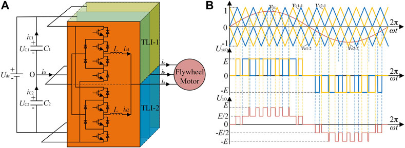
FIGURE 1. Topology and modulation of the parallel system: (A) topology, (B) interleaved parallel PWM.
Considering O as the reference point, x phase voltage of TLI-k can be expressed as
where Sxk (x = a,b,c; k = 1,2) is x phase switching signal of TIL-k inverter, and E is the voltage level. While Sxk has three possible values (Sxk = -1, 0, 1), UxkO can have three voltage levels from (2), and it is possible for UxO, the x phase voltage of the system, to obtain five voltage levels. The waveforms of UxkO and UxO is shown in Figure 1B.
Although parallel legs of the system use the same modulation wave, the switching pulses is asynchronous because of the different carriers, leading to unequal instantaneous values of leg output voltages. Then, according to Kirchhoff’s law, the voltage equation of the parallel circuit can be expressed as
where L is the inductance value of Lxk, and ixk is the x phase current of TIL-k.
From (1) (2), owing to the asynchronous switching pulses, the circulating current ihx of x phase inevitably emerges, which can be expressed as
In order to suppress circulating current, improving the stability of the parallel TLI system, the parallel circuit series filter inductors. Ignoring the magnetic saturation of the filter inductors, the inductive resistance in the AC circuit is proportional to the angular frequency of the current passing through the inductors. Therefore, although filter inductors can effectively suppress circulating current, the system inductive resistance increases, reducing the power factor when operating at high frequency.
Mechanism of Neutral-Point Potential Imbalance
The essential reason for the neutral-point potential imbalance is that the flow of the neutral current causes the neutral voltage to fluctuate. Assume that the reference direction of the neutral current is positive when it flows out of the neutral point, as shown in Figure 1A. According to Kirchhoff’s law, the relationship between neutral current and capacitor currents and the relationship between neutral voltage and capacitor voltages can be expressed as
From (4) (5), the relationship between the neutral voltage and the neutral current can be expressed as
where C is the capacitor value and U0 is the steady-state error of the neutral-point potential.
Then, during a switching period Ts, (6) can be expressed as
where u0_ average and i0_ average are the averages of u0(t) and i0(t) during a switching period, respectively.
From (7), the neutral-point potential can be balanced by eliminating the DC offset of the capacitor voltages and controlling the average neutral current i0_ average to 0.
Harmonic Analysis of the Interleaved Operation
Harmonic Characteristic
In the flywheel energy storage system, the output harmonics of the inverter generate the motor stator harmonics, which directly affect the motor harmonic losses, and then affect the stable operation of the system. Therefore, this paper regards the parallel TLIs as an integrated system to analyze its harmonic characteristic.
From Double Fourier Transform theory, the spectrum of the system switched phase output voltage can be expressed as (Holmes and Lipo, 2003)
where
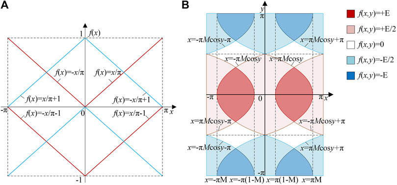
The harmonic characteristic of the parallel TLI system in the synchronous operation is the same as a single TLI, so it is unnecessary to repeat it. Moreover, for harmonic analysis of the interleaved operation, the per unit of the carrier frequency is used to simplify the analysis. The carrier waves of TLI-1 and TLI-2 in a switching period are shown in Figure 2A, while the modulation wave expression in the switching period is f(y) = Mcosy, where M is the modulation ratio. A direct comparison between the amplitudes of the carrier waves and the modulation wave is used to determine the distribution region of the switching function f(t), which is shown in the unit cell Figure 2B.
The distribution of the switching function is related to the modulation ratio M, for instance, the value of M determines that the regions of voltage level + E and -E exist or not in the unit cell. In fact, the output voltage is able to obtain five levels when M > 0.5, and the harmonic content is less because the non-zero levels of TLI-1 and TLI-2 tend to be synchronous. In the switching period, the moments when the leg output non-zero voltages of TLI-1 and TLI-2 is the same increase with M, as well as the number of synchronous switching pulses. However, when M ≤ 0.5, the output voltage can only obtain three levels and the non-zero levels of TLI-1 and TLI-2 are asynchronous, hence, the harmonic content is larger. Actually, the number of synchronous switching pulses is zero in the switching period, thus there is no moments when the leg output non-zero voltages of TLI-1 and TLI-2 is the same.
When the integral limits are determined, the harmonic characteristic of different modulation ratios in the interleaved operation is calculated as follows
where Jn (.) is the n-order Bessel function. A significant feature of the phase voltage Uo in the interleaved operation is only composed of the fundamental component and even carrier frequency with odd fundamental frequency sideband harmonic components. The fundamental component is identical to the synchronous operation, while the harmonic components is different. Also, the amplitude of the fundamental waveform is related to the modulation ratio M and DC voltage, while the amplitudes of harmonics are determined by Bessel functions when certain modulation ratio M and DC voltage are chosen. Further, the harmonics of the phase voltage Uo in interleaved operation have following characteristics:
1) When m is an odd number, partial harmonic components of TLI-1 and TLI-2 are offset, and there is no odd carrier harmonic components or odd carrier frequency with even fundamental frequency sideband harmonic components in the parallel system output voltage, compared with the synchronous operation.
2) When m is 0, the fundamental component of the parallel system output voltage is the same as the synchronous operation, and there is no DC component or baseband harmonic components.
3) When m is a non-zero even number, the harmonic components of the parallel system output voltage are in common with synchronous operation, containing even carrier frequency with odd fundamental frequency sideband harmonics.
The interleaved operation does not affect the fundamental waveform of the parallel system but can eliminate odd carrier harmonics and odd carrier frequency with even fundamental frequency sideband harmonics, compared with the synchronous operation, therefore, the system output voltage harmonic content is lower.
Harmonic Characteristic Under Unbalanced Neutral-Point Potential.
For harmonic analysis of the interleaved parallel TLI system when DC offset inevitably emerges in neutral-point potential, the distribution regions of the switching function are unchanged, but the values in the regions, also called the leg output levels are different in the unit cell.
In the interleaved operation, the possible values of the parallel TLI system output levels are + E + E0 (+E + E0)/2, 0, (-E + E0)/2, -E + E0, where E0 is the DC offset. Hence, the Fourier series expression of the output voltage for the parallel TLI system is calculated as follows
In the interleaved operation, the imbalance of neutral-point potential leads to DC bias and harmonics of even baseband component and even carrier frequency with even fundamental frequency sideband component. Furthermore, the amplitude of the DC bias is related to M and E0, as well as the amplitudes of additional harmonics which is also related to Bessel functions. An obvious merit of the interleaved operation is odd carrier harmonics and odd carrier frequency sideband harmonics are eliminated whether the neutral-point potential is balanced or not.
Neutral-point Potential Control
Zero-Sequence Voltage Injection Method
Zero-sequence voltage injection method is an effective approach to achieve the neutral-point potential balance of multilevel inverters using carrier-based PWM. The method has been widely used in TLIs, achieving excellent results. However, applications on parallel TLIs, especially interleaving, have not been discussed in the literature.
The steady-state expression of the three-phase positive sequence modulation signal vrx in the parallel TLI system can be written as
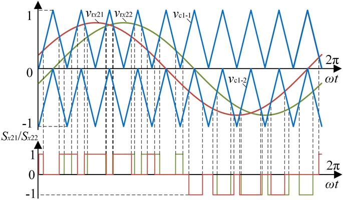
Define the x phase duty ratio of TIL-k inverter as dxk. Based on the model analysis in Section 2.1, it can be seen that carriers of the parallel legs for TLI-1 and TLI-2 in the interleaved operation are different, therefore, the duty ratios dx1 and dx2 are not equal, which causes the three-phase positive sequence modulation signal vrx cannot be directly equivalent to the duty ratio dx1 and dx2 using the impulse equivalent principle. To this end, this paper proposes an equivalent duty ratio calculation method. Based on the carrier and modulation wave of TLI-1, TLI-2 is equivalent to be modulated by carriers the same as the TLI-1 carriers and two modulation waves phase shift by a certain angle, as shown in Figure 3. The modulation wave vrx21 phase shifts forward ω0Ts/2 while the modulation wave vrx22 phase shifts backward ω0Ts/2, compared with vrx. Consequently, the impulse equivalent principle can be applied to calculate dx1 and dx2.
Hence, the duty ratio dx1 of TLI-1 is equivalent to vrx, while the duty ratio dx2 of TLI-2 can be approximately calculated in the following way
When a certain phase leg is clamped at the neutral point, this phase current flows through its corresponding clamp diode into the neutral point. Considering the existence of circulating current, the instantaneous neutral current i0(t) can be expressed as
where abs (.) is the absolute value function, and ix is x-phase load current of the parallel TLI system.
From (13) (14), the mathematical model of the average neutral current during a switching period is given by
where vx is the actual three-phase modulation signal. From section 1.2, the balance control of the neutral-point potential is to keep the average neutral current at 0 while eliminate the DC offset of capacitor voltages. Based on the mathematical model of the average neutral current, a control degree of freedom must be introduced to ensure the average neutral current is 0. The control degree of freedom is the zero-sequence voltage v0.
From (15), the mathematical expression of the zero-sequence voltage v0 is calculated as
where sign (.) is the symbol function.
Since it is not possible to determine the symbol of the three-phase modulation signal vx, the three-phase positive sequence modulation signal vrx is generally used to estimate zero sequence voltage. The estimated value of zero sequence voltage is calculated as (17), which is used to control the neutral-point potential. (17) indicates that v0st can be decoupled into two control objectives: voltage feedback control v0st-1 and current feedback control v0st-2. Firstly, the elimination of the DC offset between capacitor voltages is realized by voltage feedback control v0st-1. Then, the variation of the average neutral current is controlled to 0 by current feedback control v0st-2, maintaining the neutral-point potential balanced.
where i0′ is the capacitor voltage feedback controller output value.
Implementation and Problem
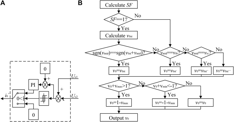
Figure 4A is the block diagram of the interleaved parallel TLI system, the center of which is the Neutral Point Potential Regulator (NPPR) based on the zero-sequence voltage injection method. The flowchart of the NPPR algorithm is shown in Figure 4B vmax, vmid and vmin are the maximum value, the middle value and the minimum value of the three-phase positive sequence modulation signal vrx, respectively.
The voltage feedback controller is a PI controller. Obviously, v0st-1 is obtained by the voltage feedback controller, while v0st-2 is obtained by the current feedback controller.
In fact, v0st is not necessarily the final injected zero sequence voltage and needs to be verified. The v0st that cannot satisfy the verification condition should be revised. There are three possible correction values for v0st, calculated as follows:
1) vmid = vra
2) vmid = vrb
3) vmid = vrc
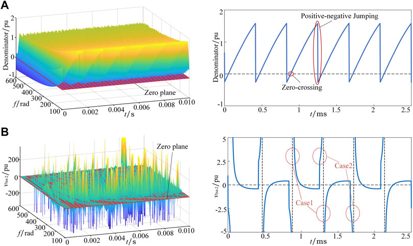
However, in order to suppress circulating current, parallel circuit series filter inductors which causes the emergence of zero-crossing and positive-negative jumping of v0st denominator. Figure 5A shows the function surface of the variables f and t, and the function curve when f is 400 Hz for v0st denominator. As the operating frequency increases, the v0st denominator is going to be 0 or even negative, and the function curves gradually change from flat curves to sawtooth curves. Hence, the phenomenon of zero-crossing and positive-negative jumping is further analyzed by taking the function curve when f is 400 Hz as an example.
For voltage feedback control, i0’ is only related to the capacitor voltage difference and the controller internal parameters. The polarity of i0’ is constant while zero-crossing and positive-negative jumping of v0st denominator inevitably emerge, leading to a sudden change of the v0st-1 polarity. Consequently, the charging and discharging ability of the parallel TLI system to the neutral-point is unbalanced, and the neutral-point potential can be completely out of control. For current feedback control, theoretically, the polarity of v0st-2 is determined by its numerator. However, zero-crossing and positive-negative jumping of the denominator cause the polarity of v0st-2 to be uncontrolled by its numerator, resulting in two extreme cases of v0st-2, as shown in Figure 5B. It can be seen from the function surface of v0st-2 that when the operating frequency is high, v0st-2 reaches extreme values. Furthermore, the function curve of v0st-2 when f is 400 Hz shows that extreme case 1 occurs when the denominator has a zero-crossing, thus the value of v0st-2 is uncertain. Extreme case 2 occurs when the denominator has a positive-negative jumping, the numerator polarity remains unchanged while the v0st-2 polarity mutates.
For the existence of filter inductors, the inductance of the parallel TLI system increases with the operating frequency, while the power factor decreases. Hence, the phase difference between the phase current and the modulation signal changes to ±π/2, which causes zero-crossing and positive-negative jumping of v0st-2 denominator. The function surfaces of v0st-2 denominator, v0st-2 numerator, and v0st-2 at different power factors are shown as Figure 6.
Although the aforementioned method can verify and revise v0st, it is not possible to correct case 1 and case 2 because of the existence of filter inductors. In order to effectively control the neutral-point potential balance of the interleaved parallel TLI system, the aforementioned method must be improved.
Improvement
Figure 7A shows the voltage feedback controller of the improved method, consisting of hysteresis controller, PI controller, etc. Based on the DC offset between capacitor voltages caused by interference or other factors, hysteresis controller chooses whether to use the PI controller or not.
In order to solve the problem mentioned above, a variable called Symbol Factor (SF) is introduced to the NPPR. SF is calculated as
According to SF, v0st is verified and revised, or just revised. The improved NPPR algorithm is shown as Figure 7B.
Simulation and Experimentation
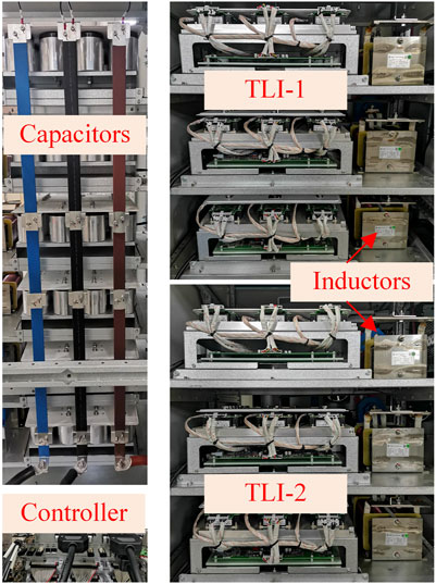
In order to verify the feasibility of the developed harmonic models and the proposed neutral-point potential control method, a MATLAB/Simulink model of 200kW parallel TLI system is constructed. Figure 8 shows the experimental platform. The consistent parameters are used for the simulation and the experiment, as listed in Table 1. In addition, TMS320F28346 (DSP) and EP3C80F484I7 (FPGA) are used to implement the experiment.
Harmonic Characteristic Comparison
Figure 9 and Figure 10 show the simulation and experimental waveforms of phase voltage for synchronous and interleaved operation under balanced and unbalanced neutral-point potential when the modulation ratio is 0.8 and the operating frequency is 400 Hz. The phase voltage waveforms for various operation modes and conditions have three and five clearly separated levels, respectively. But, there is an obvious asymmetry for the positive half wave and the negative half wave of the phase voltage when the neutral-point potential is unbalanced.

FIGURE 9. Simulation results of phase voltage for various operation modes and conditions: (A) parallel, (B) interleaved, (C) unbalanced parallel, (D) unbalanced interleaved.

FIGURE 10. Experiment results of phase voltage for various operation modes and conditions: (A) parallel, (B) interleaved, (C) unbalanced parallel, (D) unbalanced interleaved.
Figure 11 shows the calculated harmonic spectrum, the simulated harmonic spectrum and the experimental harmonic spectrum of phase voltage with the developed model. The main components among calculation, simulation and experimentation are compared clearly. Obviously, the simulated and experimental results match well with the calculated result. In fact, dead time will impact the harmonics amplitude, but the dead time of the developed system is small (3.5% of the switching period), thus its impact on harmonics is very small and can be neglected.
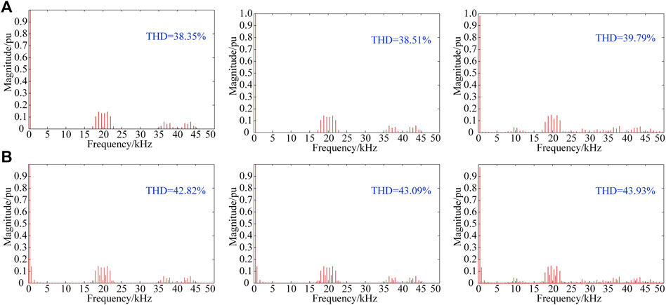
FIGURE 11. Harmonic spectrums of phase voltage for calculation, simulation and experimentation: (A) balanced, (B) unbalanced.
Figure 12 shows the line-to-line voltage THD with modulation ratios from 0.1 to 0.9 stepped by 0.1, when various parallel operations and neutral-point conditions are applied. It can be seen from the results that the harmonic contents of different operations and conditions are smaller when the modulation ratio is larger. The interleaved operation has remarkably reduced THD compared with the synchronous operation at every modulation ratio, regardless of whether the neutral-point potential is balanced. However, when the neutral-point potential is unbalanced, the line-to-line voltage quality is decreased while the harmonic content is increased at modulation ratios in the range of 0.1–0.9. Therefore, it is necessary to control the neutral-point potential to improve the harmonic characteristics. The experimental results are consistent with the simulation analysis.
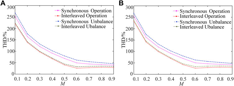
FIGURE 12. Results of line-to-line voltage THD for different modulation ratios: (A) simulation, (B) experiment.
Neutral Point Balancing Process
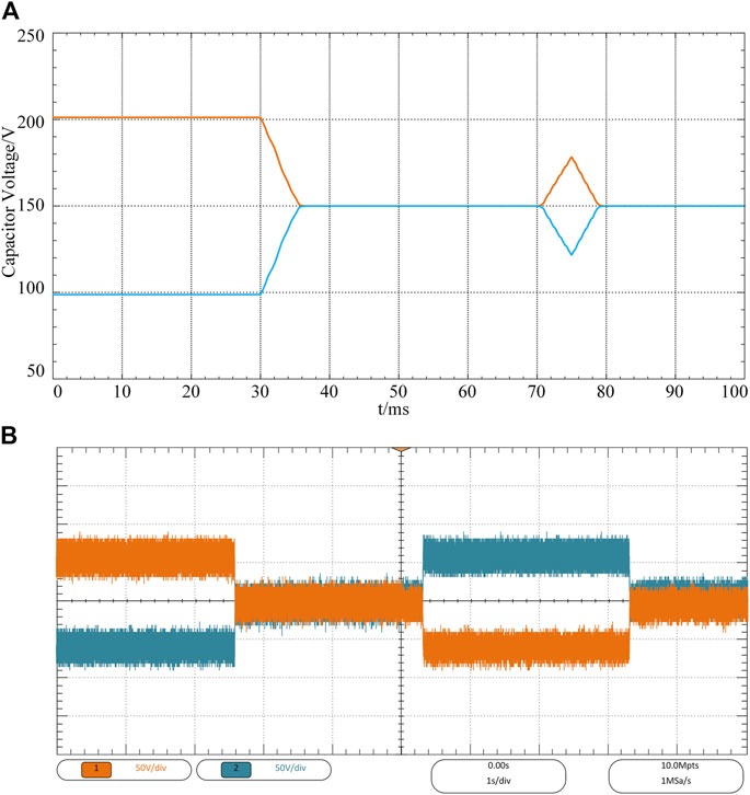
The neutral-point potential balancing algorithm is developed to the experiment platform to verify its feasibility and practicability. Figures 13A,B show the simulation and experimental waveforms of the capacitor voltage dynamic control, respectively. At the beginning, the voltage offset of the upper capacitor and the lower capacitor is 100V, and the neutral-point potential is uncontrolled thus unbalanced. The initial operating frequency of the system is 100 Hz. Figure 13A shows that at t = 30 ms, the proposed ZSVI method is enabled, the capacitor voltages are balanced quickly and remain at 150 V. However, at t = 70 ms, the operating frequency is suddenly changed to 400 Hz, the balance is disrupted, and the voltage offset increases rapidly. To remain the balance when the operating frequency is high, the improved ZSVI method is used shortly after the frequency change, thus the capacitor voltages are controlled effectively.
Figure 13B shows the same control process, and the dynamic performance of capacitor voltages is consistent with the simulation result. The slightly different is that at about 5.4s, the capacitor voltages are out of control and the lower capacitor is 100 V higher than the upper for approximately 3s, while the frequency changes from 100 to 400 Hz. But the capacitor voltages can quickly eliminate the offset and maintain the balance because of the enablement of the improved ZSVI. The results prove the ZVI method has outstanding dynamic performance when the operating frequency is low while the improved ZVI method works more evidently when the operating frequency is high.
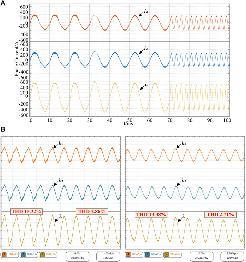
The simulation and experimental waveforms for a phase currents of TLI-1 (ia1), TLI-2 (ia2), and the output current (ia) before and after the balancing algorithm is enabled with the corresponding process of Figure 13 are shown in Figure 14. When the neutral-point potential is unbalanced, the phase currents are distorted severely. The ZVI method can restore balanced capacitor voltages and subsequently reduce the phase current distortion when the frequency is 100 Hz, while the improved ZVI method can achieve the same effect when the frequency is 400 Hz.
Conclusion
This article proposes the harmonic analytical model and neutral-point potential control method for interleaved parallel TLIs. First, the harmonic characteristic and calculation of interleaved parallel TLIs under balanced and unbalanced neutral-point potential are developed. The harmonic characteristics of interleaved operation is significantly better than the synchronous operation. Besides, the unbalance of the neutral-point potential can increase the harmonic content.
Second, the ZSVI method is proposed, which can be directly applied to balance the neutral-point potential at a lower operating frequency. However, when the system operates at a higher operating frequency, the ZSVI method is useless. The problem that the ZSVI method cannot be directly applied when the operating frequency is high is studied, and an improved neutral-point potential control algorithm is proposed. Simulation and experimental results demonstrate the validity of proposed models and algorithms.
Data Availability Statement
The original contributions presented in the study are included in the article/Supplementary Material, further inquiries can be directed to the corresponding author.
Author Contributions
ZL contributed for analysis of the work and wrote the first draft of the manuscript. SA is the corresponding author and takes primary responsibility. All authors contributed to manuscript revision, read and approved the submitted version.
Funding
This work was supported by National Natural Science Foundation of China (NSFC) under Project Numbers 52077219, 51807199.
Conflict of Interest
The authors declare that the research was conducted in the absence of any commercial or financial relationships that could be construed as a potential conflict of interest.
Publisher’s Note
All claims expressed in this article are solely those of the authors and do not necessarily represent those of their affiliated organizations, or those of the publisher, the editors and the reviewers. Any product that may be evaluated in this article, or claim that may be made by its manufacturer, is not guaranteed or endorsed by the publisher.
References
Chaturvedi, P., Jain, S., and Agarwal, P. (2014). Carrier-based Neutral point Potential Regulator with Reduced Switching Losses for Three-Level Diode-Clamped Inverter. IEEE Trans. Ind. Electron. 61, 613–624. doi:10.1109/TIE.2013.2254092
Chen, H.-C., Tsai, M.-J., Wang, Y.-B., and Cheng, P.-T. (2018). A Modulation Technique for Neutral point Voltage Control of the Three-Level neutral-point-clamped Converter. IEEE Trans. Ind. Applicat. 54, 2517–2524. doi:10.1109/TIA.2018.2799906
Chen, R., Niu, J., Gui, H., Zhang, Z., Wang, F., Tolbert, L. M., et al. (2020). Modeling, Analysis, and Reduction of Harmonics in Paralleled and Interleaved Three-Level Neutral point Clamped Inverters with Space Vector Modulation. IEEE Trans. Power Electron. 35, 4411–4425. doi:10.1109/TPEL.2019.2939727
Chenchen Wang, C., and Yongdong Li, Y. (2010). Analysis and Calculation of Zero-Sequence Voltage Considering Neutral-point Potential Balancing in Three-Level NPC Converters. IEEE Trans. Ind. Electron. 57, 2262–2271. doi:10.1109/TIE.2009.2024093
Dargahi, V., Sadigh, A. K., Khorasani, R. R., and Rodriguez, J. (2022). Active Voltage Balancing Control of a Seven-Level Hybrid Multilevel Converter Topology. IEEE Trans. Ind. Electron. 69, 74–89. doi:10.1109/TIE.2020.3048288
Di Zhang, D., Wang, F., Burgos, R., Rixin Lai, R., and Boroyevich, D. (2010). Impact of Interleaving on AC Passive Components of Paralleled Three-phase Voltage-Source Converters. IEEE Trans. Ind. Applicat. 46, 1042–1054. doi:10.1109/TIA.2010.2045336
Dolguntseva, I., Krishna, R., Soman, D. E., and Leijon, M. (2015). Contour-based Dead-Time Harmonic Analysis in a Three-Level neutral-point-clamped Inverter. IEEE Trans. Ind. Electron. 62, 203–210. doi:10.1109/TIE.2014.2327579
Gao, Z., Ge, Q., Li, Y., Zhao, L., Zhang, B., and Wang, K. (2021). Hybrid Improved Carrier-Based PWM Strategy for Three-Level neutral-point-clamped Inverter with Wide Frequency Range. IEEE Trans. Power Electron. 36, 8517–8538. doi:10.1109/TPEL.2020.3047952
Gengji, W., and Ping, W. (2016). Rotor Loss Analysis of PMSM in Flywheel Energy Storage System as Uninterruptable Power Supply. IEEE Trans. Appl. Supercond. 26, 1–5. doi:10.1109/TASC.2016.2594826
Ghanaatian, M., and Lotfifard, S. (2019). Control of Flywheel Energy Storage Systems in the Presence of Uncertainties. IEEE Trans. Sustain. Energ. 10, 36–45. doi:10.1109/TSTE.2018.2822281
Ho, C.-Y., Wang, J.-C., Hu, K.-W., and Liaw, C.-M. (2019). Development and Operation Control of a Switched-Reluctance Motor Driven Flywheel. IEEE Trans. Power Electron. 34, 526–537. doi:10.1109/TPEL.2018.2814790
Holmes, D. G., and Lipo, T. A. (2003). Pulse Width Modulation for Power Converters: Principles and Practice. Piscataway: Wiley-IEEE Press.
Jiang, C., Quan, Z., Zhou, D., and Li, Y. (2021). A Centralized CB-MPC to Suppress Low-Frequency ZSCC in Modular Parallel Converters. IEEE Trans. Ind. Electron. 68, 2760–2771. doi:10.1109/TIE.2020.2982111
Jiang, W., Wang, P., Ma, M., Wang, J., Li, J., Li, L., et al. (2020). A Novel Virtual Space Vector Modulation with Reduced Common-Mode Voltage and Eliminated Neutral point Voltage Oscillation for Neutral point Clamped Three-Level Inverter. IEEE Trans. Ind. Electron. 67, 884–894. doi:10.1109/TIE.2019.2899564
Liu, X., Liu, T., Chen, A., Xing, X., and Zhang, C. (2021). Circulating Current Suppression for Paralleled Three-Level T-type Inverters with Online Inductance Identification. IEEE Trans. Ind. Applicat. 57, 5052–5062. doi:10.1109/TIA.2021.3089115
Liu, Y., Mao, X., Ning, G., Dan, H., Wang, H., and Su, M. (2021). Model Predictive-Based Voltage Balancing Control for Single-phase Three-Level Inverters. IEEE Trans. Power Electron. 36, 12177–12182. doi:10.1109/TPEL.2021.3077011
Mazzucchelli, M., Puglisi, L., and Sciutto, G. (1981). PWM Systems in Power Converters: An Extension of the ``Subharmonic'' Method. IEEE Trans. Ind. Electron. Control. Instrum. IECI-28, 315–322. doi:10.1109/TIECI.1981.351056
Mir, A. S., and Senroy, N. (2019). Intelligently Controlled Flywheel Storage for Enhanced Dynamic Performance. IEEE Trans. Sustain. Energ. 10, 2163–2173. doi:10.1109/TSTE.2018.2881317
Nabae, A., Takahashi, I., and Akagi, H. (1981). A New Neutral-Point-Clamped PWM Inverter. IEEE Trans. Ind. Applicat. IA-17, 518–523. doi:10.1109/TIA.1981.4503992
Rafi, M. A. H., and Bauman, J. (2021). A Comprehensive Review of DC Fast-Charging Stations with Energy Storage: Architectures, Power Converters, and Analysis. IEEE Trans. Transp. Electrific. 7, 345–368. doi:10.1109/TTE.2020.3015743
Song, W., Feng, X., and Smedley, K. M. (2013). A Carrier-Based PWM Strategy with the Offset Voltage Injection for Single-phase Three-Level neutral-point-clamped Converters. IEEE Trans. Power Electron. 28, 1083–1095. doi:10.1109/TPEL.2012.2210248
Stala, R. (2013). A Natural DC-link Voltage Balancing of Diode-Clamped Inverters in Parallel Systems. IEEE Trans. Ind. Electron. 60, 5008–5018. doi:10.1109/TIE.2012.2219839
Tallam, R. M., Naik, R., and Nondahl, T. A. (2005). A Carrier-Based PWM Scheme for Neutral-point Voltage Balancing in Three-Level Inverters. IEEE Trans. Ind. Applicat. 41, 1734–1743. doi:10.1109/TIA.2005.858283
Tcai, A., Kwon, Y., Pugliese, S., and Liserre, M. (2021). Reduction of the Circulating Current Among Parallel NPC Inverters. IEEE Trans. Power Electron. 36, 12504–12514. doi:10.1109/TPEL.2021.3075562
Wan, W., Duan, S., Chen, C., and Yu, T. (2021). A Hybrid Control Method for Neutral-point Voltage Balancing in Three-Level Inverters. IEEE Trans. Power Electron. 36, 8575–8582. doi:10.1109/TPEL.2021.3051044
Xing, X., and Chen, H. (2021). A Fast-Processing Predictive Control Strategy for Common-Mode Voltage Reduction in Parallel Three-Level Inverters. IEEE J. Emerg. Sel. Top. Power Electron. 9, 316–326. doi:10.1109/JESTPE.2019.2956315
Xing, X., Li, X., Qin, C., Chen, J., and Zhang, C. (2020). An Optimized Zero-Sequence Voltage Injection Method for Eliminating Circulating Current and Reducing Common Mode Voltage of Parallel-Connected Three-Level Converters. IEEE Trans. Ind. Electron. 67, 6583–6596. doi:10.1109/TIE.2019.2939962
Yamanaka, K., Hava, A. M., Kirino, H., Tanaka, Y., Koga, N., and Kume, T. (2002). A Novel Neutral point Potential Stabilization Technique Using the Information of Output Current Polarities and Voltage Vector. IEEE Trans. Ind. Applicat. 38, 1572–1580. doi:10.1109/TIA.2002.804761
Zhang, G., Zhou, Z., Shi, T., and Xia, C. (2021). An Improved Multimode Synchronized Space Vector Modulation Strategy for High-Power Medium-Voltage Three-Level Inverter. IEEE Trans. Power Electron. 36, 4686–4696. doi:10.1109/TPEL.2020.3023622
Zhang, Q., Xing, X., and Sun, K. (2019). Space Vector Modulation Method for Simultaneous Common Mode Voltage and Circulating Current Reduction in Parallel Three-Level Inverters. IEEE Trans. Power Electron. 34, 3053–3066. doi:10.1109/TPEL.2018.2848928
Zhang, X., and Yang, J. (2018). A DC-link Voltage Fast Control Strategy for High-Speed PMSM/G in Flywheel Energy Storage System. IEEE Trans. Ind. Applicat. 54, 1671–1679. doi:10.1109/TIA.2017.2783330
Keywords: flywheel energy storage system, parallel operation, three-level inverter, interleaved, harmonic analysis, neutral-point potential control, zero-sequence voltage injection
Citation: Li Z, Nie Z, Xu J, Li H and Ai S (2022) Harmonic Analysis and Neutral-Point Potential Control of Interleaved Parallel Three-Level Inverters for Flywheel Energy Storage System. Front. Energy Res. 9:811845. doi: 10.3389/fenrg.2021.811845
Received: 09 November 2021; Accepted: 06 December 2021;
Published: 05 January 2022.
Edited by:
Liansong Xiong, Nanjing Institute of Technology (NJIT), ChinaCopyright © 2022 Li, Nie, Xu, Li and Ai. This is an open-access article distributed under the terms of the Creative Commons Attribution License (CC BY). The use, distribution or reproduction in other forums is permitted, provided the original author(s) and the copyright owner(s) are credited and that the original publication in this journal is cited, in accordance with accepted academic practice. No use, distribution or reproduction is permitted which does not comply with these terms.
*Correspondence: Sheng Ai, YWlfX3NoZW5nQDE2My5jb20=
 Zhongrui Li
 Ziling Nie