 Ting Jin1,2
 Yuebing Li
- 1State Key Laboratory of Nuclear Power Safety Monitoring Technology and Equipment, China Nuclear Power Engineering Co., Ltd, Shenzhen, China
- 2Institute of Process Equipment and Control Engineering, Zhejiang University of Technology, Hangzhou, China
As considered carbon-free, the use of nuclear energy for thermal energy generation may expand in the future, with the guarantee of safe operation of the nuclear reactor. In a nuclear reactor pressure vessel (RPV), the nozzle area is an important part of the safe operation. It bears internal pressure, axial force, and overall moment, and at the same time bears higher stress than the rest of the vessel. To assess the integrity of the nozzle structure with a crack under combined load, an accurate solution of stress intensity factors (SIF) along the crack front is necessary. To obtain the SIF, this paper proposes a solution method that uses the stress on the crack surface and the response surface method to fit the stress under the framework of the linear superposition technique. This method is the first choice to determine a series of influence coefficients under unit pressure load. Then, one can estimate the SIFs by superposition method for an arbitrary stress distribution resulted from combined loads. The proposed solution is verified for a typical RPV with cracks under internal pressure, axial force, and global bending moment. The results reveal that the proposed solution is in good agreement with the existing solutions under internal pressure. Therefore, it can be obtained that this solution can be effectively used for the structural integrity assessment of RPV with nozzle corner cracks.
Introduction
With the excessive use of fossil energy, the global greenhouse effect intensifies, which requires immediate action to reduce carbon emission (Sadekin et al., 2019). Being admitted as a carbon-free energy (Akhmat and Zaman, 2013; Gao et al., 2013), for emission reduction, nuclear energy has been used for thermal energy generation, which drives power generation, space heating, and desalination (Brook et al., 2014; Xu et al., 2021). However, its dangerous radioactivity is a crucial issue to safely operate the nuclear reactor.
As an important part of the nuclear reactor pressure vessel (RPV), ensuring the structural integrity of the RPV is the premise of the safe operation of nuclear power equipment. Due to the inconsistency of the local structure, the local stress level in the nozzle corner region may be extremely high. Under the potential thermal shock transients, fatigue cracks initiate and propagate easily. Consequently, fracture mechanics analysis of the possible impact of cracks located in the inner corners of nozzles, called corner cracks hereafter, is usually conducted to assess the structural integrity of RPV. Some specific analytical expressions have been established to determine the fracture parameters, such as stress intensity factor (SIF) and J-integrity, for applications in nuclear power plants. However, the applicability of the existing codes (ASME, 2010; British Energy, 2010) is limited to plates, elbows, and cylinders.
Presently, an exact theoretical solution or an acceptable approximate expression does not exist for nozzle corner crack fracture parameters, especially for combined loads. Further, the existing studies on SIF primarily focus on approximate analytical solutions, experimental analysis, and numerical analysis (Hardayal et al., 2008). Among them, numerical analysis has been proved to be an effective method for determining the SIF of nozzle corner cracks. The commonly used numerical methods include the finite element (FE) method and linear superposition method.
Several researchers have numerically analyzed the SIF of nozzle corner cracks by FE analysis (Broekhoven, 1975; Wilkening, 1986; Murtaza and Hyder, 2016). In addition, Ruiz (Ruiz, 1973) used the frozen-stress photo elastic technique to determine the SIFs of the corner cracks in a nozzle. Atluri and Kathiresan (Atluri and Kathiresan, 1980) proposed a method to obtain the SIFs of nozzle corner cracks in RPV. Based on the elastic stress distribution along the wall of a cylinder, Chai (Chai and Hong, 1990) proposed a formula for the SIF of a nozzle corner crack, which was particularly suitable for estimating the fatigue growth rate of the crack. Iwamatsu et al. (Iwamatsu et al., 2016) used a three-dimensional (3D) FE model for a flawed nozzle to verify that the flat plate model is suitable for obtaining a reasonable and conservative estimate of the SIF of nozzle corner crack for the influence function method. Cai et al. (Shutao and Ruijin, 1990) used the weight function method to obtain the maximum value of SIF at the crack front of a flat plate model with a circular hole loaded in uniform biaxial tension. After considering various factors, including the influence of internal pressure, circumferential stress, shape of the opening, oblique angle correction factor, curvature correction factor, and front free face correction factor, an approximate expression for the maximum SIF of an inclined nozzle corner crack was obtained. Chapuliot (2016) proposed a method for obtaining an approximate solution for SIF of nozzle corner crack under pressure thermal shock, based on the influence function method. Rui et al. (2017) compared the SIF solutions for a 1/4 infinite symmetric plate based on FEM and influence function method to obtain the influence functions for corner cracks of inlet and outlet nozzles of pressurized water reactor (PWR) pressure vessel.
The reviewed solutions of the stress intensity factor of nozzle corner crack mainly aim at the load condition dominated by internal pressure. Considering the regular stress distribution in the nozzle corner area caused by the internal pressure, the univariate stress fitting method can better represent the stress distribution. However, for the load condition dominated by nozzle load, the stress distribution in the nozzle corner area becomes irregular, and the stress distribution cannot be well characterized by the univariate stress fitting method. Therefore, to ensure the applicability of the stress intensity factor solution, this paper proposes a new stress fitting method based on multivariate to improve the solution, which is effective for both internal pressure load and complex combined load.
This study examines the SIF of nozzle corner crack based on the linear elastic fracture mechanics and linear superposition method (Shiratori and Miyoshi, 1986; Nagai et al., 2015). A new approximate solution of SIF along the crack front of the complex structure and the corresponding influence coefficients are obtained to meet the engineering application demands. Due to the complex load distribution associated with the influence coefficient, the typical internal pressure load of RPV is firstly considered, and a binary nth-order fitting polynomial characterizes the stress distribution in the nozzle corner region. Subsequently, the SIF and influence coefficients of the crack front are obtained by the superposition of the unit distributed load on the crack surface. Thus, an influence function solution is derived, and a factor is proposed to estimate the conservative solution. Finally, the accuracy and applicability of the influence function solution are verified. Considering the bending moment and axial load at the nozzle end, the SIFs of the nozzle corner crack front under different loads and combined loads are estimated. Further, based on several models, the variation in the various crack geometry parameters is considered to establish a conservative estimation method for SIF of corner cracks.
Proposal of the Method for the New Solution of Stress Intensity Factor
The linear superposition method is used to obtain the SIF solution of nozzle corner crack for engineering applications under various loading conditions. The influence coefficients of different models are obtained using FE analysis, and the corresponding influence function is obtained to estimate the SIF. It can be noted that the influence coefficients are related to the crack location, crack shape, displacement constraints, and geometry of the structure but not to the loads (Bueckner and Angew, 1970). After obtaining the influence coefficients of different models, the SIF of the models under different loads can be estimated. The characterization of the stress field under different loads is the key to the calculation of SIF.
Geometrical Description of the Problem
Generally, the structure of the nozzle shell region in RPV is extremely complex. This study focuses on the nozzle corner region. Some redundant structures cannot affect the initiation or propagation of the corner crack. Therefore, to improve the efficiency of analysis, the simplified typical RPV nozzle shell geometry is considered, and according to the relevant analysis methods, the structure is divided into defect-free and defect-containing regions. Figure 1 shows the geometry of the nozzle corner with surface crack. Here, Rm is the mean radius of the cylinder, dn is the mean diameter of the nozzle, t and tn are the wall thickness of the cylinder and nozzle, respectively, a is the depth of the semi-elliptical crack in the corner, c is the crack length, and R is the radius of the corner (all dimensions are in mm).
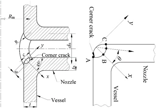
FIGURE 1. Geometry of the nozzle corner with surface crack.
The geometric parameters that may affect the influence function are considered, including crack size, corner radius, and the ratio of wall thickness to the mean radius of the cylinder. In addition, to obtain an analytical expression, the geometrical structure is normalized. The normalized crack depth α, crack size ratio φ, mean diameter ratio γ, wall thickness ratio δ, and the ratio of wall thickness to cylinder diameter κ are defined as follows:
Stress Distribution Characterized by Response Surface Method
The discontinuity of geometry, load, and material can affect the stress distribution in the nozzle corner region (Guozhong and Qichao, 1990). Further, stress distribution analysis is the basis for deriving an approximate solution of SIF. Accurately characterizing the principal stress distribution in the defect-free corner region (i.e., the hoop stress on the crack surface) can obtain an accurate SIF solution.
However, due to the complexity and discontinuity of the nozzle corner geometry, the stress distribution in this region is extremely complex. The contour of stress distribution under internal pressure is completely different from that under bending moment. The stress distribution of loads only subjected to internal pressure, as shown in Figure 2A, gradually decreases in the direction of 45° diagonal, and the stress distribution has a certain rule. The stress distribution under bending moment load and axial load is shown in Figure 2B and Figure 2C. The stress concentration area in the figure has a wide range and presents uneven distribution with the diffusion of stress. To this end, Chai and Hong (Guozhong and Qichao, 1990) suggested that for the stress field under a single internal pressure load, the stress distribution curve of the nozzle corner region can be simplified as a bisector distribution, i.e., straight lines at an angle of 45°.
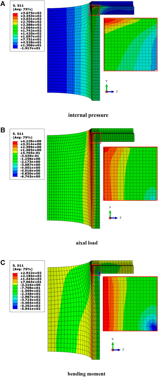
FIGURE 2. Hoop stress contours in the nozzle corner region.
Figure 2A shows the stress contours of the nozzle corner region under internal pressure. Consequently, in a certain range, the stress distribution in the nozzle corner region can be simplified by using the bisector distribution approximation, and a third-order polynomial can be used to describe the principal stress distribution on the surface of the nozzle corner (Chaudhry et al., 2014).
Moreover, the stress field can be simplified by bisector distribution under combined loads only if the fitting polynomial can accurately describe the stress distribution (Yin et al., 2011). Figure 2B and Figure 2C show the stress distribution in the nozzle corner region under axial load and global bending moment on the end face of the nozzle. Obviously, for such an irregular stress field distribution, a univariate polynomial function cannot accurately describe the stress field in the corner region (Hirokawa et al., 2016).
Therefore, to improve the accuracy, a binary function with the response surface method is used to characterize the stress distribution of nozzle corners under different loads.
where σj (j = 0–5) includes 6 simplified stress terms of the fitted stress distribution polynomial. Figure 3 shows the definition of the reference coordinates, where the origin is located in the nozzle corner on the crack face and the x-axial is 45° to the vessel axis. To ensure the accuracy of the binary fitting function and facilitate rapid analysis for engineering applications, the stress values along 3 paths (θ = −45°, 0, and 45°) in the nozzle corner region are extracted to obtain the six stress terms.
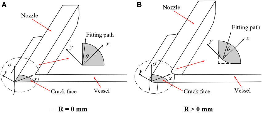
FIGURE 3. Stress fitting path.
Obtaining the New Solution With the Stress Distribution Based on Response Surface Method
The linear superposition technique is used to calculate the SIF at the crack front of a structure under complex stress distribution. SIFs due to the 6 stress terms in Eq. 4 should be calculated. Instead of analyzing the cracked structure using actual loads, a distributed pressure load σi is applied to the crack surface only. An arbitrary stress distribution is usually approximated by a third-order polynomial form. Since SIF analysis is based on linear elastic fracture mechanics, an arbitrary stress distribution can be superposed with the terms of polynomial form. Then, the SIFs can be estimated by the elastic superposition principle.
This study characterizes the stress normal to the crack face in the nozzle corner by the fitting polynomial Eq. 4 using the response surface method. The actual stress distribution is fitted using six simplified stress terms. Therefore, these unit pressure loads are applied to the assumed crack surface to determine the influence coefficients, as shown in Figure 4. The appearance of the six loads on the crack surface is different. When there is no variable X and variable Y, the unit load is uniformly distributed on the crack surface, and the magnitude is equal. When only the variable X is included, the unit load will increase with the increase of the variable X, and the increment on the path θ = −45° and θ = 45° is the same as the increment on the X axis. When the variable Y is included, the unit load on the X axis becomes 0, but the increments on the path θ = −45°and θ = 45° are the same.
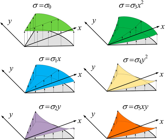
FIGURE 4. Unit loading mode on the crack surface.
For each of the individual terms (stress distributions) in Eq. 4, the SIF value
where θ is the elliptical angle denoting the point on the crack front. Although SIF values for a range of elliptical angles can be calculated during the FE analysis, three points are focused in this work, including two surface points and the deepest point as shown in Figure 1.
According to the principle of elastic superposition, SIF values
It should be noted that the actual stress is fitted using the stress field by FE for the structure without crack. However, internal pressure should be applied on the crack face for a surface crack. Therefore, the internal pressure is added as a member stress, and the SIF
To sum up, the estimation process of SIFs for nozzle corner cracks can be summarized as follows:
1) Calculate the influence coefficients by Eq. 5. For a series of nozzle crack models, unit pressure loadings are applied on the crack face with the assumed forms of six simplified stress terms.
2) Obtain the values of stress components by Eq. 4. The nozzle models without crack apply the combined loadings on the whole model, including internal pressure, axial force, and global bending moments.
3) Estimate the values of SIF by Eq. 7.
Finite Element Analysis for Stress Distribution and New Solution Verification
Model of Finite Element Method
For the nozzle corner structure presented in Figure 1 and Table 1 lists the geometrical parameters, including crack size, crack shape, corner radius of the nozzle, and the ratio of wall thickness to cylinder diameter. Based on these geometrical parameters, three-dimensional FE software ABAQUS is used for the analysis. Further, linear elastic materials with Young’s modulus of 200 GPa and Poisson’s ratio of 0.3 are used in this study.
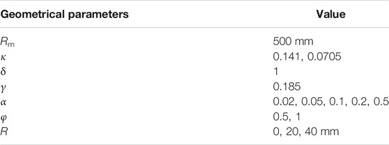
TABLE 1. Geometrical parameters of the model.
According to the symmetric structure and loads, this work establishes a 1/4 model for the load cases with internal pressure and axial force and a 1/2 model for the cases with the global bending moment. The crack-free models and crack models are also considered to obtain the stress distribution and SIFs.
The typical FE mesh models of crack-free and crack models are shown in Figure 5, and the models in Figure 5 are 1/4 FE models. The crack-free model is used to obtain the stress field, and the crack model is used to calculate SIFs. An 8-node linear brick, reduced integration, and hourglass control element (C3D8R) is selected during FE analysis. Due to the stress concentration, a criterion that the maximum principal stress at the nozzle corner should be more significant than three times the membrane stress is adopted to determine the element size. The stress results obtained under the corresponding mesh size are considered as acceptable. Therefore, the element size is considered to ensure accuracy, as shown in Figure 5.
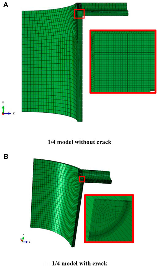
FIGURE 5. Mesh model.
Loading Conditions
Unit pressure loads are applied on the crack face with the assumed forms of six simplified stress components to obtain the influence coefficients. In order to verify the effectiveness of the influence coefficient obtained, the stress intensity factors (including internal pressure, axial force, and bending moment) under combined loads were also calculated, as shown in Figure 6.
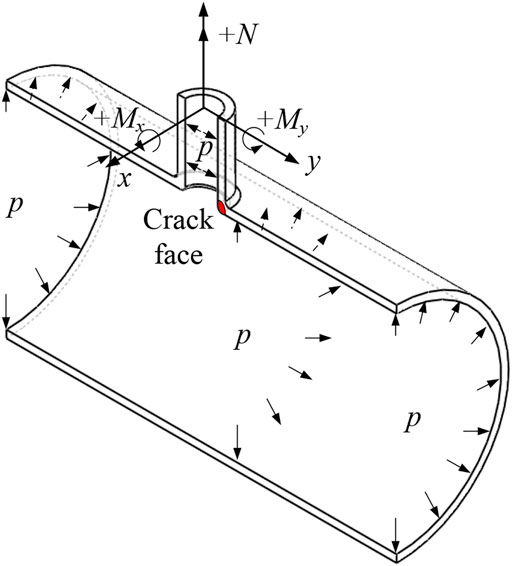
FIGURE 6. Loading condition.
Internal pressure p is applied to the internal surface of the model. The balanced force F due to internal pressure and the applied axial load N is converted to an equal pressure on the end surfaces of the nozzle. The bending moment is applied to a reference point, which is the center of the end surface of the nozzle. A kinematic coupling constraint is used to correlate the reference point with all the nodes on the end surface of the nozzle.
In the analysis models, p = 20 MPa is generally considered with different load ratios. Under the combined loading conditions, according to the definition of the load ratio of the pipe (Li et al., 2014), the following load ratio among internal pressure p, axial force N, and bending moment M can be obtained:
where ri and rm are the inner and mean radii of the nozzle, respectively. The axial force and global bending moment are assumed to be positive for those loads that result in tensile stress on the crack plane, as shown in Figure 6.
Since several combinations of axial load and bending moment are possible, the loading direction with high SIF under the most conservative conditions is considered to satisfy the engineering application requirements. Figure 7 compares the SIFs of the crack front under axial load or bending moment at the end of the nozzle in different directions. It can be seen that a negative value of either the axial load or bending moment will result in a negative SIF, which will cause the crack closure. Therefore, the positive values of the axial load and bending moment are considered. In addition, the bending moment My about the y-axial can be ignored for the calculation of SIF on the current corner crack because that moment brings about a stress parallel to the crack face. Therefore, according to the load direction shown in Figure 6, axial load + N and bending moment + Mx on the end of the nozzle are selected for SIF analysis.
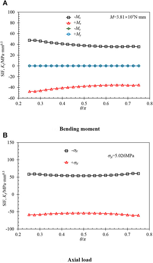
FIGURE 7. Comparison of the SIFs of the crack front under axial load or bending moment at the end of nozzle in different directions (φ = 1, κ = 0.141, R = 0 mm).
Further, for evaluating the influence function, according to the variation in the unit distribution load with the reference coordinate system, the loading mode of the unit distributed load in the FEM is applied to the crack surface.
Considering the symmetry of the RPV structure, the model’s boundary conditions are distinguished according to the different models. In the 1/4 model, symmetric boundary conditions are applied to the three symmetric interfaces in the defect-free model. However, the crack face does not have any displacement constraint in the defect-containing model. For the model with a complete nozzle, symmetric boundary conditions are applied to two symmetric interfaces, and the crack face is defined by assigning a seam. Figure 8 shows the boundary conditions of a typical 1/4 finite element model.
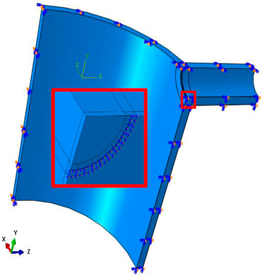
FIGURE 8. Finite element boundary conditions for 1/4 model.
Results and Discussion
Stress Distribution Results
The stress field is the basic input during the estimation of SIFs. Therefore, a two-dimensional fitting function based on multiple paths is proposed to improve the estimation precision, as described in Finite element analysis for stress distribution and new solution verification. To compare with the single path, which is mostly used in the present stress analysis method, a typical structure is performed in the stress analysis under several load cases. Three single paths are selected in the direction with θ = 0 and ±45°, and the stress values are fitted using a polynomial with third order. The following stress fitting methods are considered:
1) Two-dimensional stress fitting equation, as shown in Eq. 4.
2) One-dimensional stress fitting equation (path based on θ = 0°, the polynomial of third order).
3) One-dimensional stress fitting equation (path based on θ = 45°, the polynomial of third order).
4) One-dimensional stress fitting equation (path based on θ = −45°, the polynomial of third order).
Take structure γ = 0.185, κ = 0.141, δ = 1, φ = 1, and R = 0 mm as an example and consider the load conditions including (i) p = 20 MPa, (ii) N = 5.026 MPa, (iii) Mx = 3.81 × 10⁷ N · mm. Then, under different load conditions, the stress distribution equations under different fitting methods can be obtained by using general Eq. 10, as shown below:
Where A0-A3 are the fitting coefficients of the stress distribution polynomial. To verify the correctness of the method, the results on random paths should be selected for comparison. The stress on the path of θ = −18.4° that takes over the corner plane is compared with the FE results, as shown in Figure 9. It can be seen that the stress obtained by the response surface function is well-matched with the FE stress field, compared with other solutions that fitted on the single path. A well described stress field is the basic of SIF estimation.
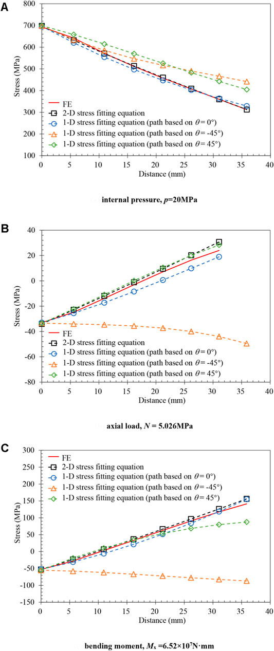
FIGURE 9. Comparison of stress fitting results (γ = 0.185, κ= 0.0705, δ = 1, φ = 1, and R = 20 mm).
Influence Coefficients
SIFs under the unit pressure distribution of the six stress terms in the response surface function should be calculated first to estimate the influence coefficients. Figure 10 shows influence coefficients along the crack front.
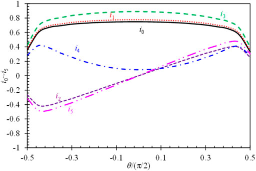
FIGURE 10. Influence coefficients along the crack front (γ = 0.185, κ = 0.141, δ = 1, φ = 0.5, and R = 0 mm).
It can be seen that the influence coefficients i0 for σ0, i1 for σ1, i3 for σ3, and i4 for σ4 are symmetric about the x-axial (θ = 0). It should be noted that the stress terms σ2 and σ5 follow a linear function of the y location. Therefore, SIFs along the crack front may be negative, although the stress term is tensile stress. This will result in a positive SIF at one surface point A or C, but a negative SIF at another surface point C or A. Using the above analysis method, the influence coefficients for several geometries with different crack sizes are calculated.
Comparison, Analysis, and Verification
Using the calculated influence coefficients of each geometric structure, the SIFs under combined loads can be estimated by Eq. 6. The FE results are used to verify the solutions obtained using Eq. 6. API 579 (American Petroleum Institute, 2007) also gives the estimation procedure to compare the SIFs of the nozzle corner crack under internal pressure. API 579 simplifies the stress distribution of the nozzle corner as a bisector distribution, where the stress distribution is characterized by a third-order polynomial along the wall thickness direction at 45° line on the corner; this is the same as Eq. 10 above.
Based on the stress distribution polynomial, API 579 provides the following equation for estimating the SIF at the deepest point of the crack:
where A0-A3 is the fitting coefficient of the stress distribution polynomial of Eq. 10. Figure 11 shows the comparison between the SIFs at the deepest point obtained using the two methods for a typical model under internal pressure load. It can be seen that the estimated SIFs by the proposed method are in good agreement with FE solutions, while the API 579 solution is more conservative than FE solutions. The SIFs at the deepest point was deduced with the increase of the crack depth a/t. At the same time, the relative error is also dropped. This may result from the stress concentration near the corner with the structure discontinues, especially for the model without nozzle fillet radius.
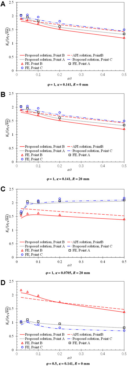
FIGURE 11. Comparison of SIF results obtained using various methods under internal pressure.
In addition, based on the influence function method, SIFs for the corner crack under combined loads are compared with the FE results, as shown in Figures 12, 13. It can be seen that the SIFs calculated under combined loads by the proposed procedure are in good agreement with the FE results with a maximum error of about 10%.
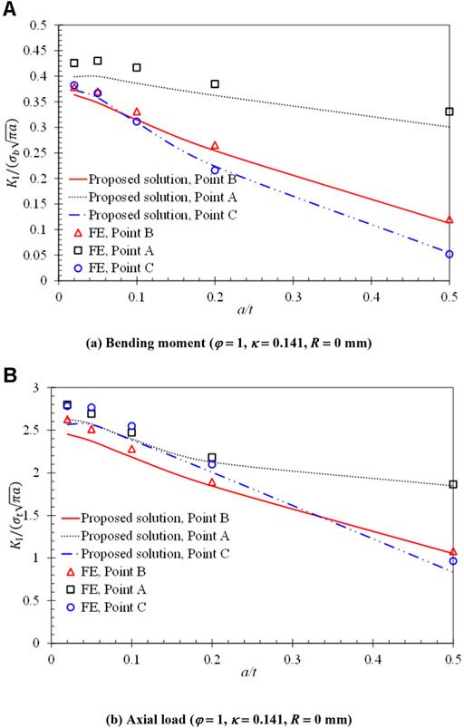
FIGURE 12. Comparison of SIF results under different loads.
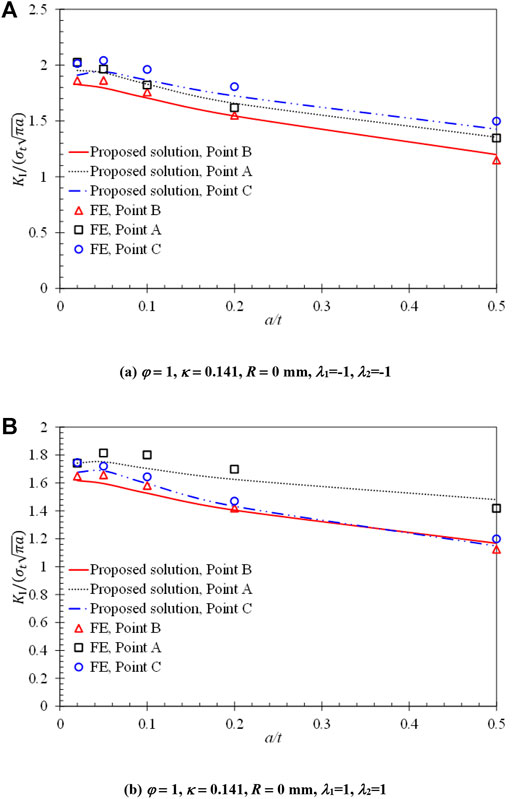
FIGURE 13. Comparison of SIF results under combined load.
Conclusion
This study used the influence function method based on FE analysis to estimate the SIF at the crack front of the nozzle corner. The stress distribution in the nozzle corner region under different loads was analyzed, and a binary function on the response surface that could represent multiple stress distributions was used as a stress fitting polynomial to characterize the stress field in the nozzle corner region. Accordingly, the influence coefficients for calculating the SIFs were obtained. Further, for facilitating engineering application, the SIFs of nozzle corner crack under different loads, different geometrical structures, and different crack sizes were estimated by using the influence function with a safety factor. The main results of the study are summarized as follows:
1) A method based on the response surface to characterize the stress distribution was proposed, and the influence function associated with SIF along the nozzle corner crack front under internal pressure, nozzle load, and the combined load was obtained. The estimation solution of the stress intensity factor of nozzle corner crack under different loads is given.
2) It is proved that the FE solution is consistent with the influence function solution, and the influence function solution is more conservative than the finite element solution. The solution of API579 standard is more conservative than that of the influence function, which shows the accuracy of influence function solution.
3) Different loading conditions had different effects on the SIFs along the nozzle corner crack front. API579 standard only applies to stress intensity factors under internal pressure, while this method applies to complex loads as well as internal pressure. The following work will consider more crack sizes and combined load analysis to further enhance the understanding of influence coefficients for engineering applications.
Data Availability Statement
The raw data supporting the conclusions of this article will be made available by the authors, without undue reservation.
Author Contributions
JT and ZW contributed to conception. JT and YL contributed to design of the study. ZH wrote the first draft of the manuscript. PL and YL performed the results analysis. ZH and DW contributed to and manuscript revision. All authors contributed to read and approved the submitted version.
Funding
The authors are grateful for the supports provided by the National Natural Science Foundation of China (51605435) and the project of State Key Laboratory of Nuclear Power Safety Monitoring Technology and Equipment (CSO-102-001).
Conflict of Interest
Author TJ, PL, DW are employed by China Nuclear Power Engineering Co., Ltd, Shenzhen.
The remaining authors declare that the research was conducted in the absence of any commercial or financial relationships that could be construed as a potential conflict of interest.
Publisher’s Note
All claims expressed in this article are solely those of the authors and do not necessarily represent those of their affiliated organizations, or those of the publisher, the editors, and the reviewers. Any product that may be evaluated in this article, or claim that may be made by its manufacturer, is not guaranteed or endorsed by the publisher.
References
Akhmat, G., and Zaman, K. (2013). Nuclear Energy Consumption, Commercial Energy Consumption and Economic Growth in South Asia: Bootstrap Panel Causality Test. Renew. Sustain. Energ. Rev. 25, 552–559. doi:10.1016/j.rser.2013.05.019
ASME (2010). ASME Boiler and Pressure Vessel Code, Section XI, Rules for Inservice Inspection of Nuclear Power Plant Components, App A. Now York: The American Society of Mechanical Engineers.
Atluri, S. N., and Kathiresan, K. (1980). Stress Intensity Factor Solutions for Arbitrarily Shaped Surface Flaws in Reactor Pressure Vessel Nozzle Corners. Int. J. Press. Vessels Piping 8, 313–322. doi:10.1016/0308-0161(80)90006-x
British Energy (2010). R6-Assessment of the Integrity of Structures Containing Defects, 4. Gloucester: ReVision.
Broekhoven, M. J. G. (1975). “Computation of Stress Intensity Factors for Nozzle Corner Cracks by Various Finite Element Procedures,” in 3rd International Conference on SMIRT, London.
Brook, B. W., Alonso, A., Meneley, D. A., Misak, J., Blees, T., and van Erp, J. B. (2014). Why Nuclear Energy Is Sustainable and Has to Be Part of the Energy Mix. Sustain. Mater. Tech. 1-2, 8–16. doi:10.1016/j.susmat.2014.11.001
Bueckner, H. F. (1970). A Novel Principle for the Computation of Stress Intensity Factors. Editor Z. Angew (Berlin, Germany: Akademie-Verlag GmbH), 529–546.
Chai, G., and Hong, Q. (1990). Stress Intensity Factor of Nozzle Corner Cracks. Eng. Fract. Mech. 38, 27–35.
Chapuliot, S. (2016). Stress Intensity Factor Calculation in Sharp and Beveled Edge Nozzle Corners. Int. J. Press. Vess. Pip. 141, S0308016115301423. doi:10.1016/j.ijpvp.2016.03.015
Chaudhry, V., Kumar, A., Ingole, S. M., Balasubramanian, A. K., and Muktibodh, U. C. (2014). Thermo-mechanical Transient Analysis of Reactor Pressure Vessel. Proced. Eng. 86, 809–817. doi:10.1016/j.proeng.2014.11.101
Gao, J., Nelson, R., and Zhang, L. (2013). Substitution in the Electric Power Industry: An Interregional Comparison in the Eastern US. Energ. Econ. 40, 316–325. doi:10.1016/j.eneco.2013.07.011
Guozhong, C., and Qichao, H. (1990). Approximate Stress-Intensity Factor Solutions for Nozzle Corner Cracks. Int. J. Press. Vessels Piping 42, 75–96. doi:10.1016/0308-0161(90)90056-n
Hardayal, S. M., Timothy, J. G., and Gary, L. S. (2008). Suggested Improvements to Appendix G of ASME Section XI Code. Now York, NY: The American Society of Mechanical Engineers
Hirokawa, F., Hayashi, M., and Masuda, M. (2016). “Defect Tolerance Assessment for ABWR Nozzle Crotch Corner,” in ASME 2016 Pressure Vessels and Piping Conference, July, Vancouver, Canada. doi:10.1115/pvp2016-63823
Iwamatsu, F., Miyazaki, K., and Masuda, M. (2016). “Applicability of Stress Intensity Factor Solution for Flat Plate to Nozzle Crotch Corner Flaw,” in ASME Pressure Vessels and Piping Conference, Vancouver, Canada, July. doi:10.1115/pvp2016-63821
Li, Y., Lei, Y., and Gao, Z. (2014). Global Limit Load Solutions for Thick-Walled Cylinders with Circumferential Cracks under Combined Internal Pressure, Axial Force and Bending Moment - Part II: Finite Element Validation. Int. J. Press. Vessels Piping 114-115, 41–60. doi:10.1016/j.ijpvp.2013.12.001
Murtaza, U. T., and Hyder, M. J. (2016). Stress Intensity Factors of Corner Cracks at Set-In Nozzle–cylinder Intersection of a PWR Reactor Pressure Vessel. J. Braz. Soc. Mech. Ences. Eng. 39, 1–11. doi:10.1007/s40430-016-0522-x
Nagai, M., Miura, N., and Shiratori, M. (2015). Stress Intensity Factor Solution for a Surface Crack with High Aspect Ratio Subjected to an Arbitrary Stress Distribution Using the Influence Function Method. Int. J. Press. Vessels Piping 131, 2–9. doi:10.1016/j.ijpvp.2015.04.003
Rui, S., Ming, C., and Yinbiao, H. (2017). “Plant Systems, Structures, Components and Materials - Research on the Fracture Mechanics Analysis Method for Reactor Pressure Vessel Nozzle Corner Flaw,” in ASME 2017 25th International Conference on Nuclear Engineering, July. (Shanghai, China).
Ruiz, C. (1973). Stress Intensity Factors for Nozzle Corner Cracks. Strain 9, 7–10. doi:10.1111/j.1475-1305.1973.tb01791.x
Sadekin, S., Zaman, S., Mahfuz, M., and Sarkar, R. (2019). Nuclear Power as Foundation of a Clean Energy Future: A Review. Energ. Proced. 160, 513–518. doi:10.1016/j.egypro.2019.02.200
Shiratori, M., and Miyoshi, T. (1986). “Analysis of Stress Intensity Factors for Surface Cracks Subjected to Arbitrarily Distributed Stresses,” in Computational Mechanics (Japan: Springer), 86.
Shutao, C., and Ruijin, W. (1990). Approximate Expression of the Maximum Value of the Stress Intensity Factor (SIF) of Oblique Nozzle Corner Cracks. Int. J. Press. Vess. Pip. 42, 353–361.
Wilkening, W. W. (1986). 3-D Elastic Analysis of a Circular Nozzle Corner Crack. J. Press. Vessel Technol. 108, 474–478. doi:10.1115/1.3264815
Xu, Y., Mao, C., Huang, Y., Shen, X., Xu, X., and Chen, G. (2021). Performance Evaluation and Multi-Objective Optimization of a Low-Temperature CO2 Heat Pump Water Heater Based on Artificial Neural Network and New Economic Analysis. Energy 216, 119232. doi:10.1016/j.energy.2020.119232
Yin, S., Bass, B. R., and Stevens, G. L. (2011). “Stress and Fracture Mechanics Analyses of Boiling Water Reactor and Pressurized Water Reactor Pressure Vessel Nozzles,” in Proceedings of the ASME 2011 Pressure Vessels and Piping Division Conference, July (Baltimore, Maryland, USA). doi:10.1115/pvp2011-57014
Nomenclature
a Depth of the semi-elliptical crack in the corner
c Crack length
dn Mean diameter of the nozzle
t, tn Wall thickness of the cylinder and nozzle
Rm Mean radius of the cylinder
R Radius of the corner
α Normalized crack depth
φ Crack size ratio
γ Mean diameter ratio
δ Wall thickness ratio
κ Ratio of wall thickness to cylinder diameter
σj Distributed pressure load
θ Elliptical angle
p Internal pressure
F Balanced force
N Applied axial load
M Bending moment
ri, rm Inner and mean radii of the nozzle
Ai Fitting coefficients
Keywords: nozzle corner crack, stress intensity factor, influence coefficient, internal pressure, nuclear reactor, carbon-free energy
Citation: Jin T, He Z, Liu P, Wang Z, Li Y and Wang D (2021) A New Stress Intensity Factor Solution Based on the Response Surface Method for Nozzle Corner Cracks in Nuclear Reactor for Thermal Energy Generation. Front. Energy Res. 9:801919. doi: 10.3389/fenrg.2021.801919
Received: 26 October 2021; Accepted: 09 November 2021;
Published: 09 December 2021.
Edited by:
Wei Wu, City University of Hong Kong, Hong Kong SAR, ChinaReviewed by:
Nian Li, Zhejiang University, ChinaJie Yang, University of Shanghai for Science and Technology, China
Copyright © 2021 Jin, He, Liu, Wang, Li and Wang. This is an open-access article distributed under the terms of the Creative Commons Attribution License (CC BY). The use, distribution or reproduction in other forums is permitted, provided the original author(s) and the copyright owner(s) are credited and that the original publication in this journal is cited, in accordance with accepted academic practice. No use, distribution or reproduction is permitted which does not comply with these terms.
*Correspondence: Yuebing Li, eWJsaUB6anV0LmVkdS5jbg==