 Yicen Zhang
 Yang Du
 Xiaochen Lu
 Pan Zhao
 Yiping Dai
95% of researchers rate our articles as excellent or good
Learn more about the work of our research integrity team to safeguard the quality of each article we publish.
Find out more
ORIGINAL RESEARCH article
Front. Energy Res. , 14 January 2022
Sec. Process and Energy Systems Engineering
Volume 9 - 2021 | https://doi.org/10.3389/fenrg.2021.801428
The wide utilization of solar energy is beneficial for the emission reduction of carbon dioxide. This paper proposes a novel power cycle system driven by solar energy, which consists of a recompression supercritical carbon dioxide cycle (RSCO2) and an ammonia-water cooling-power cycle (ACPC). The power system operates in a “self-production and self-sale” mode, which means that the refrigeration capacity produced by the ACPC is utilized to cool the main compressor inlet fluid of the RSCO2. The comprehensive energy and exergy analyses of the proposed novel system are presented. The effects of the six parameters on the system thermodynamic performance are evaluated, which are direct normal irradiation, the ammonia concentration of a basic solution, the pinch point temperature difference of an evaporator, the effectiveness of a recuperator, the pressure ratio of the RSCO2 and the molten salt outlet temperature. The results show that compared with the stand-alone RSCO2, the net power and energy efficiency of the proposed system are improved by 15.94 and 10.61%, respectively. In addition, the increasing ammonia concentration of the basic solution leads to the rise of the ACPC refrigeration output, and the inlet temperature of the main compressor can be declined to 32.97°C with the ammonia concentration of the basic solution of 0.88. Moreover, when the effectiveness of the recuperator in RSCO2 rises up to 0.98, the system energy and exergy efficiencies can reach their maximum value of 30.68 and 33.10%, respectively.
The utilization of renewable energy can effectively reduce carbon dioxide emission, which contributes to the sustainable development of green energy society. Tower solar power system (TSP) is comprised of heliostat filed, central receiver and molten salt circulation. TSP absorbs radiation energy from Sun for heating molten salt. Due to the reason that the heliostat field can concentrate sunlight on a central receiver with high irradiation intensity, the molten salt circulation operates in high temperature (Srilakshmi et al., 2015). Ashour et al. (2021) built a prototype of TSP, the system includes 10 heliostats, and the highest simulation temperature is 521°C. In addition, molten salt released 12.52 kW power to water in the heat exchanger. With such a characteristic of providing high-temperature heat, many scholars have researched the possibility and performance of different combined power cycle configurations with TSP (Kasaeian et al., 2020).
Jiang et al. (2021) proposed a novel tower solar aided coal-fired power generation system with a double reheat ultra-supercritical boiler; the steam in boiler is heated to 565°C under the baseline condition. The analysis results presented that the maximum system power output and solar-to-electricity conversion efficiencies are 23.69 MW and 29.57%, respectively. Javadi et al. (2021a) evaluated the energy, exergy, and economic and environmental performance of a combined power cycle with TSP. Meanwhile, they proposed three different configurations, and configuration b) which use solar power to heat air at compressor outlet realize highest energy and exergy efficiency of 51.38 and 41.75%, respectively. In another research (Javadi et al., 2021b), Javadi et al. established a multigeneration system model based on double-flash geothermal power plant, TSP, organic Rankine cycle (ORC), lithium bromide single-stage chiller, and alkaline electrolyzer. This complex system could produce hydrogen and output power and refrigeration, simultaneously. Izadi et al. (2021) utilized TSP to drive a gas turbine (GT) cycle, the waste heat from GT is recovered by Rankine cycle, ORC, and absorption chiller system. The designed energy efficiency and power output are 41.77% and 6,746 kW, respectively. Majidi et al. (2021) presented a novel layout of a combined GT and ORC cycle with TSP. When the organic working fluid of ORC is R123, the optimized cycle performance of power output and energy efficiency are 46 MW and 52.27%, respectively. Merchán et al. (2021) analyzed a tower hybrid GT solar system about its thermo-economic performance. It found out that when the turbine inlet temperature rises from 1,300 to 1,500 K, the levelized cost of electricity (LCOE) decreases from 188US$/MWh to 150US$/MWh. In AlKassem’s research (AlKassem, 2021), it was shown that with the combination of GT, the total installed cost of solar field was lower than stand-alone TSP. Furthermore, a high field efficiency ranged from 53 to 59% was achieved, which leads to a high thermal-to-electric efficiency.
Among various kinds of power cycle systems, the supercritical carbon dioxide cycle (SCO2) is one of the most compatible cycles, which has a better thermodynamic performance with high-temperature heat source like TSP. The working fluid of SCO2 is supercritical carbon dioxide, which has the characteristics of high specific heat capacity and low compression power consumption. Moreover, SCO2 has the advantages of low cost, high efficiency, small equipment size, simple structure, and high energy density (Liao et al., 2019; White et al., 2021). SCO2 has developed a variety of different types, and RSCO2 is a blooming type that has a high operating efficiency. RSCO2 has two compressors and two recuperators, the SCO2 fluid in the main compressor has high density and compressibility. At the same time, RSCO2 is able to reduce the pinch point temperature difference of LTR and the heat taken away by a precooler. During recent years, lots of studies have been made in the field of combined SCO2 and TSP system.
Zhu et al. (2021) designed a ZrC/W-based printed circuit heat exchanger, which can bear a high operating temperature around 700°C. The heat exchanger was used especially for safe and effective heat-exchanging process between SCO2 and molten salt. Yang et al. (2020) investigated the thermodynamic performance of a combined SCO2 and steam Rankine cycle with TSP and compared it with a stand-alone SCO2 system. The analysis results revealed that the introduction of a cascaded system improved 9.5% of electricity production; in addition, the exergy destruction of the precooler and heat exchanger is decreased significantly. Kasra et al. (Mohammadi et al., 2020) investigated the thermodynamic performance of a combined TSP and GT system using SCO2 as a bottom cycle. Compared with a non-TSP system, the introduction of TSP increases LCOE by 40% from $59.23 to $83.16/MWh; nevertheless, specific fuel consumption and specific CO2 emission were reduced by 27.5 and 29%, respectively. Atif et al. (Atif and Al-Sulaiman, 2017) made a research about the energy and exergy performance of a combined TSP and RSCO2 system in different locations. It was summarized that the heliostat field accounts for the highest average exergy destruction, followed by the combustion chamber. The highest annual average heat collected is for Madinah (938,400 kWh/day). Fahad et al. (Al-Sulaiman and Atif, 2015) compared the thermodynamic performance of five different SCO2 configurations with TSP. The conclusion revealed that with the combination of TSP, RSCO2 performs the highest cycle energy efficiency of 52% and system energy efficiency of 40%. Linares et al. (2020) proposed numerous novel configurations of the combined SCO2 and TSP system to adapt to different operating conditions. For wet cooling condition, the reheating SCO2 type is recommended, which leads to an energy efficiency of 54.6% and an investment of 8,662 $/kW, while intercooling with reheating type is better for dry cooling condition, whose energy efficiency and investment are 52.6% and 8,742 $/kW, respectively. Neises et al. (Neises and Turchi, 2019) developed a novel partial-cooling SCO2 model with TSP. Before entering a recompressor, the flow temperature was decreased by a cooler and then compressed by a pre-compressor, which leads to high operating pressure ratio and low LCOE.
Meanwhile, a multigeneration system that can meet the need of different kinds of energy becomes more and more popular; some scholars made efforts to output power and refrigeration simultaneously through the combined SCO2 and TSP system. Tsimpoukis et al. (2021) studied a cooling, power, and heating generation system, which consists of SCO2, ejector refrigeration cycle (ERC), a solar receiver, and biomass boiler. The power production efficiency, combined power and cooling production efficiency, and total trigeneration efficiency under the baseline condition are 11.77, 66.09 and 163.70%, respectively. Li and Wang (2019) combined SCO2 with a transcritical carbon dioxide refrigeration cycle. The precooler outlet fluid in SCO2 splits, and one of them flows into an evaporator to produce refrigeration; when the evaporating temperature is 273.15 K, the combined system realizes 2.45% higher than the separation system on exergy efficiency.
However, a few researchers find that it is interesting that the refrigeration produced by the cooling cycle can be used to cool the fluid at a compressor inlet. Part of the heat energy from the power cycle is used to drive the cooling cycle, and the refrigeration capacity from the cooling cycle is used to cool the fluid at the compressor inlet. This kind of “self-production and self-sale” method is capable to improve the overall system efficiency. Du et al. (2021) used refrigeration produced by ERC to cool the compressor inlet air in GT; thus, the proposed combined GT-KC-ERC system realized a 219.4 kW more net power and 764.2 kW more cooling capacity than a stand-alone GT-KCS system. Ma et al. (2018) integrated the LiBr absorption refrigeration cycle with RSCO2, and refrigeration from the LiBr absorption refrigeration cycle cools the inlet temperature of the main compressor down to 37.07°C. It is concluded that optimized system energy and exergy efficiencies are 5.19 and 6.12% higher than stand-alone RSCO2, respectively. The exergy destruction in a high-temperature recuperator (HTR) and the precooler are significantly reduced. Mohammed et al. (2020) replaced the LiBr absorption refrigeration cycle with ERC, and via the introduction of ERC, the optimized system energy and exergy efficiency improved by 36.2% and 28.6%, respectively.
However, unlike the LiBr fluid in the LiBr absorption refrigeration cycle or most organic refrigerants in ERC, the ammonia-water mixture solution is a non-azeotropic fluid that has a variable-temperature evaporation process. Therefore, the ammonia-water mixture fluid can match with the changing temperature of the heat source during the heat-exchanging process, which is capable to lower heat loss and exergy destruction. As a result, the ammonia-water mixture solution has been widely studied and used in different kinds of power cycle systems, like the Kalina cycle and ammonia-water absorption refrigeration cycle. In this paper, an ammonia-water power and cooling system/ACPC is adopted (Wang et al., 2016); the ACPC is not only able to output power, but it also adds a separator after the ammonia-water turbine. The secondary rich-ammonia vapor is condensed and throttled for refrigeration output, which provides a new idea for refrigeration production.
Based on the above researches, this paper improves the system performance of a solar-powered RSCO2 by introducing an ammonia-water cooling-power system. The system consists of a TSP, an RSCO2, and an ACPC. The ACPC is driven by the heat from an HTR in RSCO2; the refrigeration produced by the ACPC is utilized to cool the main compressor inlet temperature in RSCO2, and more details about the system description are clearly shown in Section 2. In this paper, the thermodynamic mathematical models of the proposed system are established and separately validated. The simulation result under the baseline condition is given; the energy and exergy analysis on a system performance is made. Then, the thermodynamic performance between a power cycle subsystem with stand-alone RSCO2 is evaluated and compared. The effects of the six parameters on the system’s thermodynamic performance are studied, including direct normal irradiation, DNI, the ammonia concentration of a basic solution, x, the pinch point temperature difference of an evaporator, ∆Te, the effectiveness of a recuperator εR, the pressure ratio of RSCO2, PR, and molten salt outlet temperature Tb.
In this paper, Section 1 is the introduction. Section 2 is the circulation schematic description of the proposed solar-powered RSCO2-ACPC system. Section 3 lists the necessary mathematical equations for a model establishment. Section 4 presents the analysis result and discussion. Section 5 is the summarized conclusion.
Figure 1 shows the systematic flow scheme of the proposed innovative solar-powered RSCO2-ACPC system. The total system is departed into three parts, which are a TSP, a RSCO2, and an ACPC. The TSP absorbs heat from Sun, and the molten salt in TSP transfers the heat to CO2 in RSCO2. In RSCO2, the CO2 at the HTR outlet passes through a heat exchanger and provides heat to the ammonia-water basic solution in the ACPC. The ammonia-water basic solution output power in an ammonia-water turbine and produces refrigeration in the evaporator. Afterwards, the refrigeration produced in the evaporator from the ACPC is utilized to cool the main compressor inlet CO2 in RSCO2. Thus, the total system achieves a better thermodynamic performance via lower compressor power consumption. The system realizes the “self-production and self-sale” effect through the connection of a heat exchanger and the evaporation between RSCO2 and ACPC. Regarding the deep connection between RSCO2 and ACPC, the RSCO2-ACPC is sometimes seen as an integrity of the power cycle subsystem in the following sections.
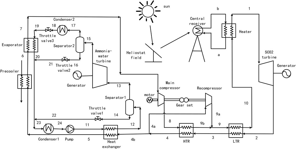
FIGURE 1. Flow scheme of proposed RSCO2-ACPC system.
The TSP includes a heliostat field, a central receiver, and molten salt circulation; the Sun projects its sunlight on a heliostat field, which consists of many reflectors. In the central receiver, the molten salt flows through the receiver and improves its temperature by concentrated sunlight. In addition, the molten salt is made of 60% NaNO3 and 40% KNO3 in this paper.
The RSCO2 includes a heater, an SCO2 turbine, a generator, an HTR and low-temperature recuperator (LTR), a heat exchanger, a precooler, an evaporator, a main compressor, a recompressor, a motor, and a gear set. Firstly, CO2 gains heat from high-temperature molten salt in the heater, and outputs power through the SCO2 turbine and generator 1. Then, the exhausted CO2 provides heat for compressed CO2 in LTR and HTR. At the HTR outlet, CO2 splits into two flows: one flow is compressed by the recompressor and mixed with heated CO2 from an LTR; another flow passes through the heat exchanger for the improving temperature of the ammonia-water basic solution in ACPC, and it is cooled successively in the precooler and evaporator. The low-temperature CO2 is then compressed by the main compressor and absorbs heat in the HTR. After mixing with the recompressor outlet flow, CO2 absorbs heat again in the HTR and flows into the heater finally.
The ACPC subsystem includes two separators, an ammonia-water turbine, a generator, two condensers, three throttle valves, and a pump. The ammonia-water basic solution improves its temperature by high-temperature CO2 in a heat exchanger. Then, the ammonia-water basic solution separates into prime weak-ammonia liquid and prime rich-ammonia vapor in separator 1. After generating electricity through the ammonia-water turbine and generator 2, the exhausted prime rich-ammonia vapor separates into a secondary weak-ammonia liquid and secondary rich-ammonia vapor in separator 2. The secondary rich-ammonia vapor is condensed in condenser 2 and throttled in throttle valve 3. In the evaporator, the low-temperature secondary rich-ammonia vapor provides refrigeration for cooling CO2 in RSCO2. Afterwards, the secondary rich-ammonia vapor mixes with prime weak-ammonia liquid and prime rich-ammonia vapor and forms the ammonia-water basic solution. Then, the ammonia-water basic solution is condensed in condenser 1 and pumped in a pump. At last, the ammonia-water basic solution flows into the heat exchanger for another circulation.
This paper proposes an innovative solar-powered RSCO2-ACPC system; the MATLAB R2020b software is used for system mathematical simulation. Besides, the thermodynamic properties of carbon dioxide and ammonia-water mixture are obtained from NIST REFPROP 9.1. Some necessary assumptions are listed as follows:
1) The system operates under a steady state.
2) The inlet and outlet status of each system equipment is regarded as a balanced status.
3) The pressure loss of equipment and pipelines are neglected.
4) Except for the solar central receiver, the heat losses between the equipment and environment are neglected.
5) The system equipment and pipeline have good airtightness and no leakage.
6) The fluid at the condenser outlet is in a saturated state.
7) The enthalpy at the throttle valve inlet and outlet are equal.
8) The vapor and liquid at separator outlet are saturated.
9) There is no mechanical energy loss of the gear set.
The TSP includes a heliostat field, a central receiver and molten salt circulation; the energy Qsun and exergy Esun projected from the Sun are (Petela, 1964)
where Ah denotes the heliostat field area, m2; T0 denotes environment temperature, K; and Tsun denotes the Sun’s surface temperature, K.
Then, the heliostat field reflects the sunshine to the central receiver subsystem. For the heliostat field, its energy efficiency, ηh, is very difficult to keep accurate (Yao et al., 2009; Collado and Guallar, 2013); in this paper, ηh is set as a constant. The received energy, Qcr, and exergy, Ecr, are (Xu et al., 2011)
In this paper, the shape type of the central receiver is the cavity receiver, molten salt flows through the receiver to absorb heat and transfer it to carbon dioxide. The thermodynamic properties of molten salt are given based on Eqs 5–8 (Zavoico, 2001), and the Tms ranges from 270 to 600°C.
In the central receiver, there are four types of heat losses, which are conduction loss, reflection loss, convection loss, and emission loss (Li et al., 2010). Thus, the energy, Qms, and exergy, Ems, of molten salt absorbed from the receiver are (Xu et al., 2011)
where Qloss denotes the sum of four types of heat losses, kW; ηr denotes the energy efficiency of the central receiver; mms denotes the molten salt mass flow rate, kg∙s−1; cp,ms denotes the specific heat capacity of molten salt, J∙kg−1∙K−1; Ta and Tb denote the inlet and outlet temperature of molten salt, K.
For the carbon dioxide and ammonia-water mixture fluid, the exergy can be described as (Eq. 12)
where the subscript i denotes a specific state point; the subscript 0 denotes the environment state.
In the heater, the heat received by CO2 and exergy destruction can be described as the following equations:
where mco2 denotes the CO2 mass flow rate, kg∙s−1; h denotes enthalpy, kJ∙kg−1; and I denotes exergy destruction, kW.
In an SCO2 turbine, the power output, Wt,co2, and exergy destruction, It,co2 are
where ηt,co2 denotes the isentropic energy efficiency of an SCO2 turbine.
In the HTR, the exhausted flow provides heat for compressed CO2 flow; the energy balance equation and exergy destruction are
The LTR condition is similar to the HTR:
where msr denotes the mass flow rate that flows through the main compressor, kg∙s−1.
For both HTR and LTR, the effectiveness can be described separately in Eq. 22 and Eq. 23, in particular, the εHTR and εLTR stay the same in this paper, and the total exergy destruction of a recuperator is expressed in Eq. 24.
In a heat exchanger, CO2 flow provides heat for an ammonia-water basic solution.
where m12 denotes the mass flow rate of the ammonia-water basic solution, kg∙s−1.
In the precooler, the CO2 flow is cooled by water, and the cooling capacity, Qpc, is
In the evaporator, the CO2 flow is cooled again by secondary rich-ammonia vapor flow, and cooling process meets the following equations:
where m17 denotes the mass flow rate of secondary rich-ammonia vapor flow, kg∙s−1.
For the main compressor and recompressor, the pressure ratio, power consumption, and exergy destruction are
where PR denotes the pressure ratio of the compressor outlet to inlet; ηmc、ηrc denotes the isentropic energy efficiency of the main compressor and recompressor; and Wmc、Wrc denote the power consumed by the main compressor and recompressor, kW.
The separator separates the ammonia-water basic solution into a rich ammonia vapor and a weak ammonia liquid, and the process meets the mass balance equation, ammonia mass balance equation, and energy balance equation. For separator 1, the balance equations are
where x denotes the ammonia concentration of the solution.
For separator 2, the balance equations are
The exergy destruction of separator one and separator two are
In an ammonia-water turbine, the power output, Wt,aw, and exergy destruction, It,aw, are
where ηt,aw denotes the isentropic energy efficiency of the ammonia-water turbine.
In condenser 1 and condenser 2, the ammonia-water mixture fluid is condensed by water; the cooling capacity and exergy destruction are
In this paper, the enthalpy at the throttle valve inlet and outlet are equal; thus, the enthalpy balance equations and exergy destruction can be described as Eqs 56–62.
In the pump, the consumed power, Wp, and exergy destruction, Ip, are
where ηp denotes the isentropic energy efficiency of the pump.
For the mixing process, as there is no fluid leakage, the process meets mass and ammonia mass balance equations. The energy balance equation and exergy destruction are
The system performance parameters include the turbine power output, the consumed power of the compressor and the pump, evaporator refrigeration capacity, net power output, energy efficiency, and exergy efficiency. Some parameters have been introduced above, and others are listed in the following equations:
where Wpower and Ipower denote the net power output and total exergy destruction of a power cycle subsystem, kW; Qeva denotes the evaporator refrigeration capacity, kW; ηpower,ene and ηpower,exe denotes the energy and exergy efficiency of a power cycle subsystem, ηtotal,ene and ηtotal,exe denote the energy and exergy efficiency of the total system.
In order to formulate a validated mathematical model, three subsystems, including the central receiver, RSCO2, and ACPC, are separately compared with the data from the former reference. Table 1 lists the validation condition, and Table 2 presents the validation results with relative error.
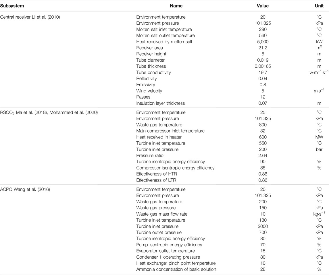
TABLE 1. System model validation condition.
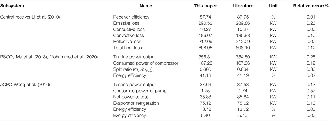
TABLE 2. System model validation result.
Table 2 illustrates that the maximum relative error is 0.57%, and most relative errors are lower than 0.20%, which indicates that the accuracy of subsystem models is acceptable. Thus, the validation provides a solid foundation for the system simulation of the proposed solar-powered RSCO2-ACPC system.
Since the subsystem models have been established and validated, the system simulation and performance analysis can follow the logical calculation flow scheme in Figure 2. Meanwhile, for a clear presentation of results and analysis, this section is divided into three parts, which are the baseline condition, comparison, and parameter effects.
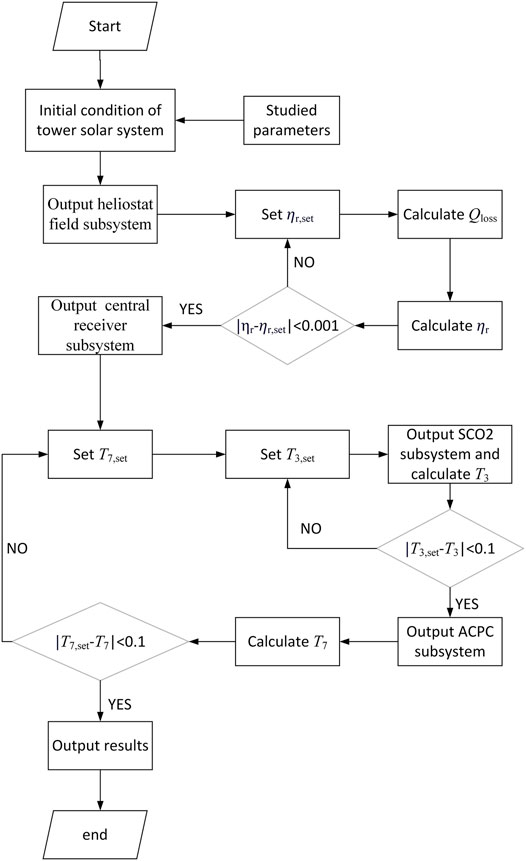
FIGURE 2. Logical calculation flow scheme.
The system baseline simulation condition of a power cycle subsystem is given in Table 3; some values are chosen on the basis of former work to realize better compatibility with state-of-the-art researches. Table 4 gives all detailed numerical data about each state point.
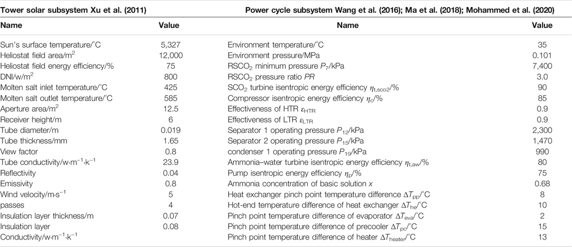
TABLE 3. System baseline simulation condition.
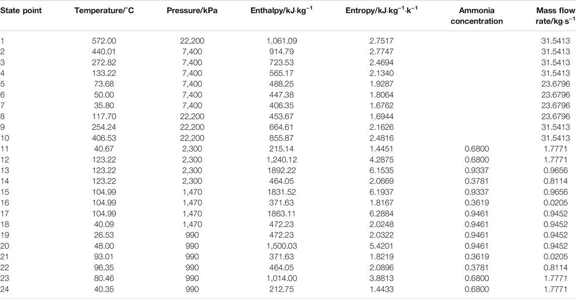
TABLE 4. System baseline simulation result of state point.
In Table 5, the thermodynamic performance of a power cycle subsystem is presented, and Table 6 shows the thermodynamic performance about the energy and exergy of a total system. Under the baseline condition, the solar central receiver energy efficiency is 89.9%. The refrigeration produced by ACPC is 971.46 kW, which has a huge contribution on lowering the inlet temperature of the main compressor; therefore, the system power output reaches 2,766.48 kW. However, the ammonia-water turbine power output is only 58.63 kW, which accounts for merely 2.12% of the system total power output. In addition, the energy and exergy efficiencies of a power cycle subsystem are 42.74 and 70.91%, respectively. Energy and exergy efficiencies of total system are 28.82 and 31.10%, respectively.
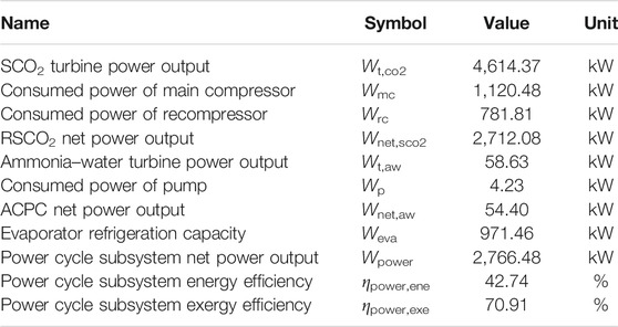
TABLE 5. System baseline simulation result of power cycle subsystem performance.
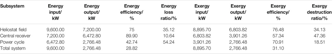
TABLE 6. System baseline simulation result of total system performance.
In Table 6, the result shows that under the baseline condition, although the power cycle subsystem accounts for the most energy loss ratio of 54.24%, it has the least exergy destruction ratio of 18.51%, while the solar central receiver shows the opposite effects. In the solar central receiver, the concentrated sunlight with high temperature firstly provides tremendous heat to improve the receiver surface temperature, and the receiver transfers the heat to molten salt later. With a big temperature difference and huge heat energy in this two-step heat transfer process, the exergy destruction ratio of the central receiver reaches 47.36% of total system.
Furthermore, the exergy destruction ratio about each component of a power cycle subsystem is illustrated in Figure 3. The maximum exergy destruction of 25.42% is related to two recuperators, which is caused by the low effectiveness of a recuperator. After the recuperator, the exergy destruction of an SCO2 turbine and two compressors reach 19.72 and 17.83%, respectively. However, because of the low temperature difference at the heater inlet and outlet, the exergy destruction in the heater is very low. Besides, the exergy destruction in two separators is close to zero, which means that the separation process is very ideal and the mass flow rate of ammonia-water mixture fluid is small.
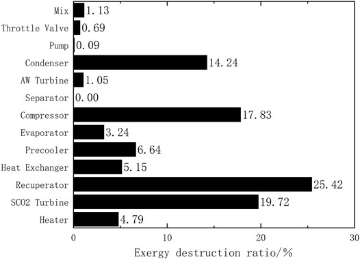
FIGURE 3. Exergy destruction ratio of equipment in power cycle subsystem.
In Table 7, as the SCO2 turbine power output of power cycle subsystem and stand-alone RSCO2 stays the same, the power cycle subsystem can lower the inlet temperature of the main compressor from 50 to 35.80°C. Compared with stand-alone RSCO2, the power consumed by the main compressor decreases from 1,510.54 to 1,120.48 kW. However, due to the rise of the recompressor outlet temperature, the power consumed by recompressor increases from 717.70 to 781.81 kW. Furthermore, the system power output goes up from 2,386.13 to 2,766.48 kW, which induces the improvement of energy efficiency from 38.64 to 42.74%.
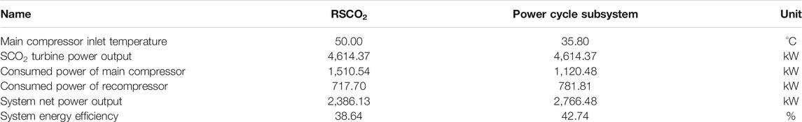
TABLE 7. System performance comparison between power cycle subsystem and stand-alone RSCO2.
In this part, the influence of the different studied parameters on the system thermodynamic performance are evaluated, including direct normal irradiation, DNI, the ammonia concentration of the basic solution, x, the pinch point temperature difference of the evaporator, ∆Te, the effectiveness of the recuperator εR, the pressure ratio of RSCO2, PR, and molten salt outlet temperature, Tb; the results are shown in following figures.
In Figure 4A, the solar central receiver energy efficiency linearly rises about 0.2–0.5% with a 40 W m−2 increment of DNI; the reason for this phenomenon is that a higher DNI results in more power input and a higher receiver surface temperature, simultaneously. As increasing receiver surface temperature causes more heat loss, the receiver energy efficiency becomes lower. However, the increment of energy loss caused by a higher receiver surface temperature is lower than that of the power input. From Figure 4B, when the DNI rises from 600 W m−2 to 1,000 W m−2, the total net power grows faster than EVA refrigeration; it is because on one side, a higher DNI induces a higher mass flow rate of CO2, which results in growing total net power; on the other side, the increase of EVA refrigeration will decrease the main compressor inlet temperature, which reversely improves the total net power. In Figure 4C, system energy and exergy efficiencies increase with similar increment, from 28.18 to 29.17% and 30.41–31.48%, respectively. Moreover, the highest power output produced by an SCO2 turbine is 5.84 MW when the DNI is 1,000 W m−2.
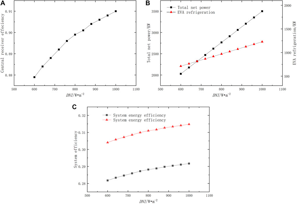
FIGURE 4. Effect of direct normal irradiation DNI.
As shown in Figure 5A, x has a positive effect on EVA refrigeration and it grows faster when x is lower. Meanwhile, the change of x only directly influences the performance of ACPC, so the increment of total net power output is smaller than that of EVA refrigeration, which is unlike the influence of DNI. In other words, for gaining more power output, it would be better to improve the performance of RSCO2 than ACPC. In Figure 5B, when x rises from 0.48 to 0.88, the power cycle energy and exergy efficiencies go up from 40.92 to 43.93% and 67.90–72.89%, respectively. Meanwhile, due to the high refrigeration capacity with the high mass ratio of ammonia, the inlet temperature of the main compressor can be as low as 32.97°C with an x of 0.88.
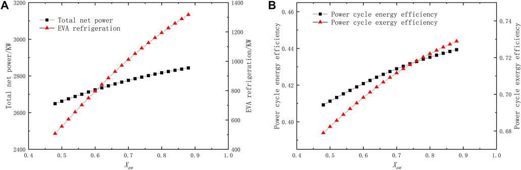
FIGURE 5. Effect of ammonia concentration of basic solution x.
Figure 6 illustrates the effect of the evaporator pinch point temperature difference, ∆Teva. When ∆Teva rises from 1 to 10°C, total net power, power cycle energy and exergy efficiencies slightly decrease from 2,767.26 to 2,757.55 KW, 42.75–42.60% and 70.93–70.68%, respectively. In addition, with a 0.5°C increment of ∆Teva, the EVA refrigeration goes down about 2.42–4.76 kW, and the inlet temperature of the main compressor rises to about 0.02–0.05°C. As a result, the influence of ∆Teva on the system thermodynamic performance is limited, and it is less important to improve the heat-exchanging performance of EVA and get lower ∆Teva.
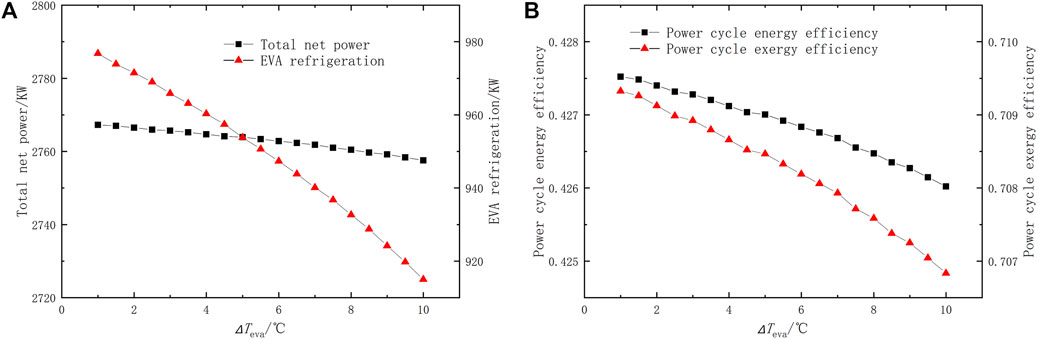
FIGURE 6. Effect of evaporator pinch point temperature difference ∆Teva.
As seen in Figure 7, a higher εR will lower the inlet temperature of the ammonia-water turbine in ACPC, which leads to lower EVA refrigeration and power output of ACPC. Nevertheless, a rising εR is able to reduce the giant heat waste and exergy destruction in the recuperator, which leads to better system thermodynamic performance. Thus, in Figure 7(A) When εR rises from 0.87 to 0.98, total net power goes up from 2,698.90kW to 2,944.84kW. In Figure 7(B) When εR rises from 0.87 to 0.98, the power cycle energy and exergy efficiencies increase from 41.70 to 45.50% and 69.18–75.48%, respectively. Compared with other studied parameters, εR has the most positive effects on system thermodynamic performances; when εR rises up to 0.98, the system energy and exergy efficiencies can reach 30.68 and 33.10%, respectively.
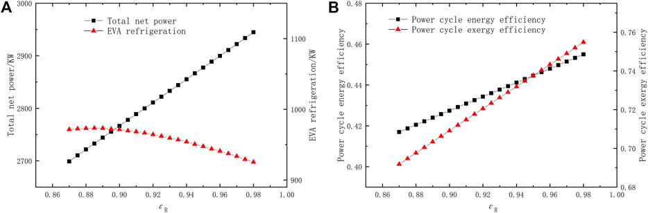
FIGURE 7. Effect of recuperator effectiveness εR.
Figure 8 presents the effect of RSCO2 pressure ratio, PR. In Figure 8(A), when PR increases from 2.54 to 2.96, the total net power rises dramatically. However, the increment becomes smaller when PR increases from 2.96 to 3.2, and there is a maximum value of 2,769.03 kW when PR is 3.14. Meanwhile, PR has a reverse influence on EVA refrigeration; the maximum value of EVA refrigeration is 981.44 kW when PR is 2.66. Naturally, rising PR will enlarge the power produced by the SCO2 turbine and consumed by the main compressor at the same time. In this paper, the power consumed by the main compressor is also influenced by EVA refrigeration. Therefore, at first, the change of EVA refrigeration stays small with rising PR, which strongly controls the power consumed by the main compressor; then, EVA refrigeration goes down dramatically when PR is high. As a result, the total net power becomes steady with higher PR. In Figure 8(B), similar to the change of total net power, when PR is 3.14, the power cycle energy and exergy efficiencies reach their maximum value of 42.78 and 70.98%, respectively.
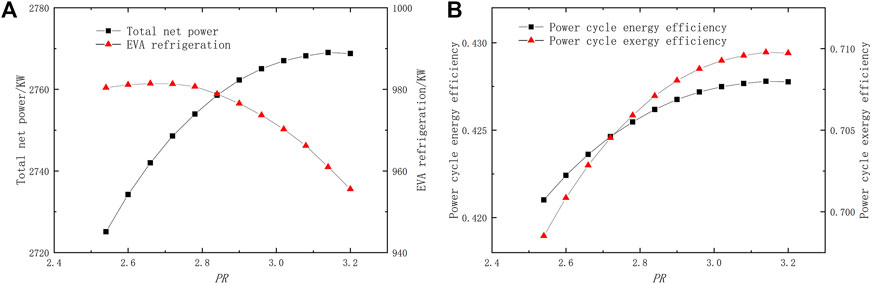
FIGURE 8. Effect of RSCO2 pressure ratio PR.
Figure 9 shows the effect of the molten salt outlet temperature, Tb. Owing to the reason that the molten salt chosen in this paper is 60% NaNO3 and 40% KNO3, which becomes unstable around 600°C, the change of Tb ranges from 546 to 602°C. In Figure 9(A), When Tb rises, the central receiver energy efficiency goes down from 90.6 to 89.5%. The phenomenon is caused by a higher temperature difference between the environment and receiver surface, which contributes to more heat loss. In Figure 9(B), since the input energy from Sun remains constant, the rise of Tb will diminish the mass flow rate of both CO2 in RSCO2 and the ammonia-water mixture fluid in ACPC. Therefore, the power both produced and consumed are reduced; however, because a higher Tb causes a higher inlet temperature of the SCO2 turbine simultaneously, the decrement of the consumed power of the main compressor is bigger than the power produced by the SCO2 turbine; thus, the total net power still rises with increasing Tb. A 4°C increment of Tb leads to a 2.92–4.95 kW decrement of EVA refrigeration and 7.84–12.96 kW increment of total net power, respectively. In Figure 9(C), with a 4°C increment of Tb, the system energy and exergy efficiencies increase to about 0.08–0.13% and 0.09–0.14%, respectively.
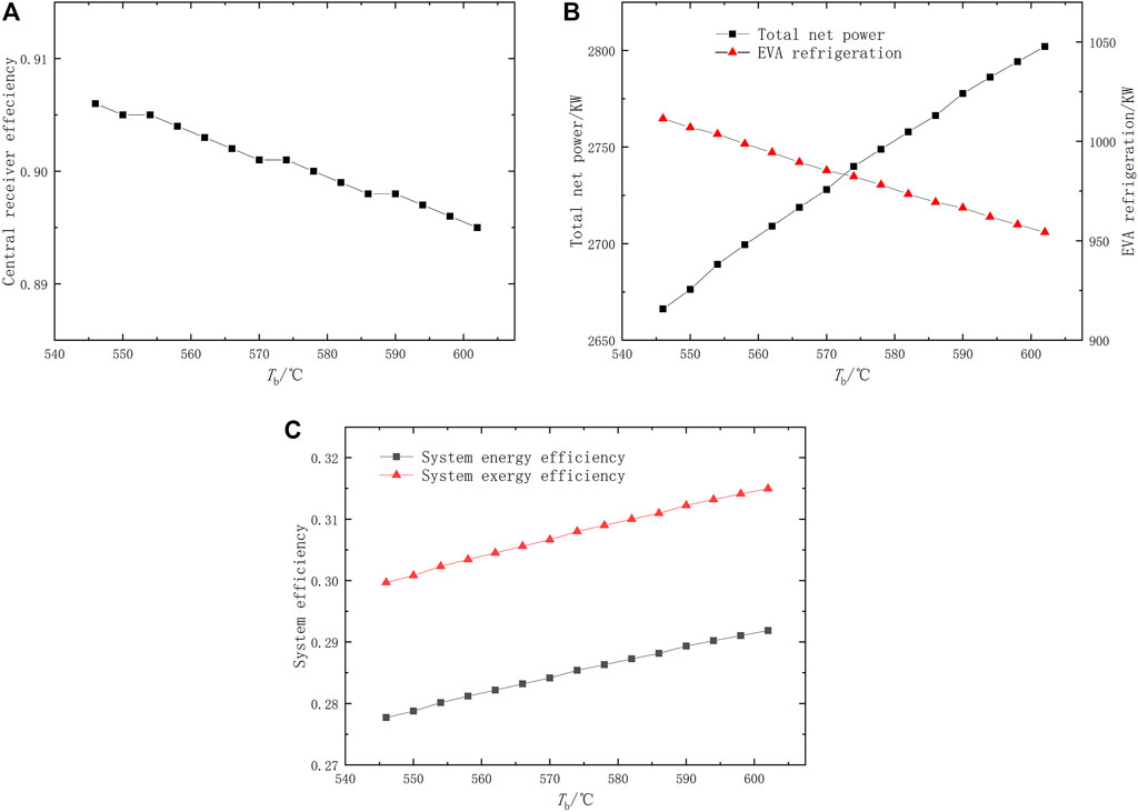
FIGURE 9. Effect of molten salt outlet temperature Tb.
This paper improves the thermodynamic performance of a solar-powered RSCO2 cycle by introducing an ammonia-water cooling-power system. The system consists of a TSP, an RSCO2 subsystem, and an ACPC subsystem. The ACPC is driven by the heat from HTR in RSCO2, and the refrigeration produced by the ACPC is utilized to cool the main compressor inlet air of RSCO2.
Under the baseline condition, the solar central receiver energy efficiency is 89.9%. The refrigeration produced by the ACPC is 971.46 kW, and system net power reaches 2,766.48 kW. Moreover, the energy and exergy efficiency of total system are 28.82 and 31.10%, respectively. Compared with the stand-alone RSCO2, the proposed system can lower the inlet temperature of main compressor from 50 to 35.80°C. The power consumed by main compressor is thus decreased by 390.1 kW, which leads to the improvement of energy efficiency from 38.64 to 42.74%.
The energy and exergy efficiencies of the total system increase with the rising direct normal irradiation, the ammonia concentration of the basic solution, the pressure ratio of RSCO2, the effectiveness of the recuperator, and the outlet temperature of molten salt. In addition, when effectiveness of recuperator rises to 0.98, the system energy and exergy efficiencies can reach to 30.68 and 33.10%, respectively. The inlet temperature of main compressor can be declined to 32.97°C with the ammonia concentration of the basic solution of 0.88. The highest power output produced by an SCO2 turbine is 5.84 MW when the DNI is 1000 W m−2.
The original contributions presented in the study are included in the article/supplementary material, further inquiries can be directed to the corresponding author.
YZ: Methodology, software, formal analysis and writing—original draft. YaD: idea, conceptualization and validation. XL: data curation and visualization. PZ: review and editing. YiD: review, editing and supervision.
This research was partially supported the National Natural Science Foundation of China (Grant No. 51976145).
The authors declare that the research was conducted in the absence of any commercial or financial relationships that could be construed as a potential conflict of interest.
All claims expressed in this article are solely those of the authors and do not necessarily represent those of their affiliated organizations, or those of the publisher, the editors and the reviewers. Any product that may be evaluated in this article, or claim that may be made by its manufacturer, is not guaranteed or endorsed by the publisher.
The authors are grateful to Yi Wu for her helpful discussion on related topics in this paper.
Al-Sulaiman, F. A., and Atif, M. (2015). Performance Comparison of Different Supercritical Carbon Dioxide Brayton Cycles Integrated With a Solar Power Tower. Energy. 82, 61–71. doi:10.1016/j.energy.2014.12.070
AlKassem, A. (2021). A Performance Evaluation of an Integrated Solar Combined Cycle Power Plant With Solar Tower in Saudi Arabia. Renew. Energ. Focus. 39, 123–138. doi:10.1016/j.ref.2021.08.001
Ashour, A. I., Almitani, K. H., and Abu-Hamdeh, N. H. (2021). Developing and Improving a Prototype Scale Concentrating Solar Power Tower-System. Sustainable Energ. Tech. Assessments. 45, 101105. doi:10.1016/j.seta.2021.101105
Atif, M., and Al-Sulaiman, F. A. (2017). Energy and Exergy Analyses of Solar Tower Power Plant Driven Supercritical Carbon Dioxide Recompression Cycles for Six Different Locations. Renew. Sustainable Energ. Rev. 68, 153–167. doi:10.1016/j.rser.2016.09.122
Collado, F. J., and Guallar, J. (2013). A Review of Optimized Design Layouts for Solar Power Tower Plants With Campo Code. Renew. Sustainable Energ. Rev. 20, 142–154. doi:10.1016/j.rser.2012.11.076
Du, Y., Jiang, N., Zhang, Y., Wang, X., Zhao, P., Wang, J., et al. (2021). Multi-Objective Optimization of an Innovative Power-Cooling Integrated System Based on Gas Turbine Cycle with Compressor Inlet Air Precooling, Kalina Cycle and Ejector Refrigeration Cycle. Energ. Convers. Management. 244, 114473. doi:10.1016/j.enconman.2021.114473
Izadi, A., Ahmadi, P., Bashiri Mousavi, S., and Fakhari, I. (2021). A Comparative Optimization of a Trigeneration System With an Innovative Integration of Solar Heliostat Towers and Hydrogen Production Unit. Sustainable Energ. Tech. Assessments. 47, 101522. doi:10.1016/j.seta.2021.101522
Javadi, M., Jafari Najafi, N., Khalili Abhari, M., Jabery, R., and Pourtaba, H. (2021a). 4E Analysis of Three Different Configurations of a Combined Cycle Power Plant Integrated With a Solar Power tower System. Sustainable Energ. Tech. Assessments. 48, 101599. doi:10.1016/j.seta.2021.101599
Javadi, M., Khalili Abhari, M., Ghasemiasl, R., and Ghomashi, H. (2021b). Energy, Exergy and Exergy-Economic Analysis of a New Multigeneration System Based on Double-Flash Geothermal Power Plant and Solar Power tower. Sustainable Energ. Tech. Assessments. 47, 101536. doi:10.1016/j.seta.2021.101536
Jiang, Y., Duan, L., Pang, L., and Song, J. (2021). Thermal Performance Study of Tower Solar Aided Double Reheat Coal-Fired Power Generation System. Energy. 230, 120857. doi:10.1016/j.energy.2021.120857
Kasaeian, A., Bellos, E., Shamaeizadeh, A., and Tzivanidis, C. (2020). Solar-Driven Polygeneration Systems: Recent Progress and Outlook. Appl. Energ. 264, 114764. doi:10.1016/j.apenergy.2020.114764
Li, B., and Wang, S.-s. (2019). Thermo-Economic Analysis and Optimization of a Novel Carbon Dioxide Based Combined Cooling and Power System. Energ. Convers. Management. 199, 112048. doi:10.1016/j.enconman.2019.112048
Li, X., Kong, W., Wang, Z., Chang, C., and Bai, F. (2010). Thermal Model and Thermodynamic Performance of Molten Salt Cavity Receiver. Renew. Energ. 35 (5), 981–988. doi:10.1016/j.renene.2009.11.017
Liao, G., Liu, L., E, J., Zhang, F., Chen, J., Deng, Y., et al. (2019). Effects of Technical Progress on Performance and Application of Supercritical Carbon Dioxide Power Cycle: A Review. Energ. Convers. Management. 199, 111986. doi:10.1016/j.enconman.2019.111986
Linares, J. I., Montes, M. J., Cantizano, A., and Sánchez, C. (2020). A Novel Supercritical CO2 Recompression Brayton Power Cycle for Power Tower Concentrating Solar Plants. Appl. Energ. 263, 114644. doi:10.1016/j.apenergy.2020.114644
Ma, Y., Zhang, X., Liu, M., Yan, J., and Liu, J. (2018). Proposal and Assessment of a Novel Supercritical CO2 Brayton Cycle Integrated With LiBr Absorption Chiller for Concentrated Solar Power Applications. Energy. 148, 839–854. doi:10.1016/j.energy.2018.01.155
Majidi, M., Behbahaninia, A., Amidpour, M., and Sadati, S. H. (2021). Thermoeconomic Optimization of a Novel High-Efficiency Combined-Cycle Hybridization With a Solar Power Tower System. Energ. Convers. Management. 244, 114461. doi:10.1016/j.enconman.2021.114461
Merchán, R. P., Santos, M. J., García-Ferrero, J., Medina, A., and Hernández, A. C. (2021). Thermo-Economic and Sensitivity Analysis of a Central Tower Hybrid Brayton Solar Power Plant. Appl. Therm. Eng. 186, 116454. doi:10.1016/j.applthermaleng.2020.116454
Mohammadi, K., Ellingwood, K., and Powell, K. (2020). Novel Hybrid Solar Tower-gas Turbine Combined Power Cycles Using Supercritical Carbon Dioxide Bottoming Cycles. Appl. Therm. Eng. 178, 115588. doi:10.1016/j.applthermaleng.2020.115588
Mohammed, R. H., Qasem, N. A. A., and Zubair, S. M. (2020). Enhancing the thermal and Economic Performance of Supercritical CO2 Plant by Waste Heat Recovery Using an Ejector Refrigeration Cycle. Energ. Convers. Management. 224, 113340. doi:10.1016/j.enconman.2020.113340
Neises, T., and Turchi, C. (2019). Supercritical Carbon Dioxide Power Cycle Design and Configuration Optimization to Minimize Levelized Cost of Energy of Molten Salt Power Towers Operating at 650 °C. Solar Energy. 181, 27–36. doi:10.1016/j.solener.2019.01.078
Petela, R. (1964). Exergy of Heat Radiation. J. Heat Transfer. 86 (2), 187–192. doi:10.1115/1.3687092
Srilakshmi, G., Venkatesh, V., Thirumalai, N. C., and Suresh, N. S. (2015). Challenges and Opportunities for Solar Tower Technology in India. Renew. Sustainable Energ. Rev. 45, 698–709. doi:10.1016/j.rser.2015.02.016
Tsimpoukis, D., Syngounas, E., Bellos, E., Koukou, M., Tzivanidis, C., Anagnostatos, S., et al. (2021). Investigation of Energy and Financial Performance of a Novel CO2 Supercritical Solar-Biomass Trigeneration System for Operation in the Climate of Athens. Energ. Convers. Management. 245, 114583. doi:10.1016/j.enconman.2021.114583
Wang, J., Wang, J., Zhao, P., and Dai, Y. (2016). Thermodynamic Analysis of a New Combined Cooling and Power System Using Ammonia-Water Mixture. Energ. Convers. Management. 117, 335–342. doi:10.1016/j.enconman.2016.03.019
White, M. T., Bianchi, G., Chai, L., Tassou, S. A., and Sayma, A. I. (2021). Review of Supercritical CO2 Technologies and Systems for Power Generation. Appl. Therm. Eng. 185, 116447. doi:10.1016/j.applthermaleng.2020.116447
Xu, C., Wang, Z., Li, X., and Sun, F. (2011). Energy and Exergy Analysis of Solar Power Tower Plants. Appl. Therm. Eng. 31 (17-18), 3904–3913. doi:10.1016/j.applthermaleng.2011.07.038
Yang, H., Li, J., Wang, Q., Wu, L., Reyes Rodríguez-Sanchez, M., Santana, D., et al. (2020). Performance Investigation of Solar tower System Using Cascade Supercritical Carbon Dioxide Brayton-Steam Rankine Cycle. Energ. Convers. Management. 225, 113430. doi:10.1016/j.enconman.2020.113430
Yao, Z., Wang, Z., Lu, Z., and Wei, X. (2009). Modeling and Simulation of the pioneer 1MW Solar Thermal Central Receiver System in China. Renew. Energ. 34 (11), 2437–2446. doi:10.1016/j.renene.2009.02.022
Zavoico, A. B. (2001). Solar Power Tower Design Basis Document, Revision 0. United States: U.S. Department of Energy Office of Scientific and Technical Information.
Zhu, Q., Tan, X., Barari, B., Caccia, M., Strayer, A. R., Pishahang, M., et al. (2021). Design of a 2 MW ZrC/W-Based Molten-Salt-To-sCO2 PCHE for Concentrated Solar Power. Appl. Energ. 300, 117313. doi:10.1016/j.apenergy.2021.117313
A Area/m2
ACPC Ammonia-water cooling and power cycle
aw Ammonia water
c Compressor
co2 Carbon dioxide
CO2 Carbon dioxide fluid
con Condenser
CP Specific heat capacity/kJ∙kg−1∙k−1
cr Central receiver
DNI Direct normal irradiation/w∙m−2
E Exergy/kW
eva Evaporator
exe Exergy efficiency
G Heat energy/kW
h Heliostat field
h Enthalpy/kJ∙kg−1
he Heat exchanger
heater Heater
HTR High-temperature recuperator
I Exergy destruction/kW
LTR Low-temperature recuperator
m Mass flow rate/kg∙s−1
mc Main compressor
mix Mixing process
ms Molten salt
net Net power
P Pressure
pre Precooler
PR Pressure ratio
pp Pinch point
pump Pump
rc Recompressor
R Recuperator
RSCO2 Recompression supercritical carbon dioxide cycle
sr Split ratio
sep Separator
SCO2 Supercritical carbon dioxide cycle
Sun Sun
total Total system
tv Throttling valve
TSP Tower solar power system
T Temperature
W Power/kW
x Ammonia concentration
η Efficiency
μ Dynamic viscosity/Pa·s
λ Conductivity/w∙k−1∙m−1
1–24,a,b State point
ε Effectiveness of recuperator
ρ Density/kg∙m−3
Keywords: recompression supercritical carbon dioxide cycle, solar power, ammonia-water mixture fluid, cooling and power production, thermodynamic performance
Citation: Zhang Y, Du Y, Lu X, Zhao P and Dai Y (2022) Performance Improvement of a Solar-Powered Recompression Supercritical Carbon Dioxide Cycle by Introducing an Ammonia-Water Cooling-Power System. Front. Energy Res. 9:801428. doi: 10.3389/fenrg.2021.801428
Received: 25 October 2021; Accepted: 09 December 2021;
Published: 14 January 2022.
Edited by:
Xiaoxiao Li, Chongqing University, ChinaReviewed by:
Zongliang Qiao, Southeast University, ChinaCopyright © 2022 Zhang, Du, Lu, Zhao and Dai. This is an open-access article distributed under the terms of the Creative Commons Attribution License (CC BY). The use, distribution or reproduction in other forums is permitted, provided the original author(s) and the copyright owner(s) are credited and that the original publication in this journal is cited, in accordance with accepted academic practice. No use, distribution or reproduction is permitted which does not comply with these terms.
*Correspondence: Yiping Dai, eXBkYWlAbWFpbC54anR1LmVkdS5jbg==
Disclaimer: All claims expressed in this article are solely those of the authors and do not necessarily represent those of their affiliated organizations, or those of the publisher, the editors and the reviewers. Any product that may be evaluated in this article or claim that may be made by its manufacturer is not guaranteed or endorsed by the publisher.
Research integrity at Frontiers
Learn more about the work of our research integrity team to safeguard the quality of each article we publish.