 Xiangzhe Kong
 Xiaobin Jian1
 Wenjie Li
 Chuan Lu
 Shurong Ding
- 1Institute of Mechanics and Computational Engineering, Department of Aeronautics and Astronautics, Fudan University, Shanghai, China
- 2Science and Technology on Reactor System Design Technology Laboratory, Nuclear Power Institute of China, Chengdu, China
UMo/Zr monolithic fuel plates have a promising application prospect in high flux research reactors. To prolong the service life and achieve safety design, the in-pile macro-mesoscale thermal-mechanical behavior of the fuel plate needs further simulation research. In this study, for the fuel meat, the theoretical models of the equivalent fission gas bubble volume fraction, the gas-bubble inner pressure and the maximum skeleton stress are developed, with the effects of bubble distribution pattern involved. The application into the simulation of the in-pile macro-mesoscale thermal-mechanical behavior of the UMo/Zr monolithic fuel plate indicates that the maximum skeleton stress of the fuel meat basically rises with the burn-up, and may reach four times of the macroscale first principal stress of the fuel meat. The distribution patterns of the gas bubbles in the fuel meat might have a distinct influence on the maximum skeleton stress, and the most conservative results of the simple cubic arrangement can be used for the failure prediction of the fuel meat.
Introduction
UMo alloys are the main fuel candidates in the development of RERTR (Reduced Enrichment for Research and Test Reactors) program due to advantages of high uranium density and steady irradiation performance (Snelgrove et al., 1997; Burkes et al., 2015). Compared to UMo dispersion fuel elements, UMo monolithic fuel elements possess a higher uranium density (Gan et al., 2017). Aluminum alloy is the first choice for the cladding material in the research-test-reactor used fuel elements, because of its high thermal conductivity, low price and low density (Pasqualini et al., 2016). However, the fission fragment bombardment of the interface between aluminum alloy cladding and UMo fuel meat takes place under the in-pile irradiation environments, which will weaken the strength of UMo/Al interface resulting in the failure of fuel element and the reduction of the service life of fuel element (Pasqualini et al., 2016). The irradiation experiment results (Pasqualini et al., 2016) indicated that the interfacial performance of UMo/Al monolithic fuel element could be obviously improved by adding a Zr diffusion barrier layer between UMo fuel meat and Al alloy cladding or using Zr alloy cladding. Compared to Al alloy, the mechanical properties of Zr Alloy at high temperatures are more similar to UMo alloy (Pasqualini et al., 2016). Hence, UMo/Zr monolithic fuel elements have a good application prospect in the future high flux research reactor (Gonzalez et al., 2015; Zhao et al., 2015) and advanced pressurized water reactor, because of its low neutron absorption cross section, good mechanical properties and corrosion resistance. The researches on the fabrication process and irradiation-induced behavior for UMo/Zr monolithic fuel elements have been implemented (Kong et al., 2016; Pasqualini et al., 2016).
For the safety operation of the reactor, the UMo/Zr monolithic fuel plates should be ensured with enough strength, stiffness and in-pile stability, which are closely related to the irradiation behaviors of UMo fuel meat and Zr alloy cladding together with their intense mechanical interactions. The UMo/Zr monolithic fuel plate experiences complex thermal-mechanical behavior under neutron irradiation. Firstly, the heat generation of the UMo fuel meat will cause non-uniform temperature field in the fuel plate, which causes certain temperature gradients and thermal stress in the fuel element (Yan et al., 2019a). In addition, the solid and gas fission products lead to the volume growth of the UMo fuel meat (Kong et al., 2018). The fission gas swelling is dependent on the nucleation and growth of fission gas bubbles and affected by stress state, fission rate, temperature and recrystallization effect (Kong et al., 2016; Yan et al., 2019a; Kong et al., 2018), etc. As shown in Figure 1, the fission gas bubbles make the UMo fuel meat a porous structure, which will continue to evolve with the development of burn-up (Meyer et al., 2014). The external stresses will be balanced by the ones in the solid part of the fuel meat, called as the fuel skeleton, and the pore pressures. Large gas bubbles or pores are observed in the fuel meat near the interface between fuel meat and the Zr barrier (Jue et al., 2018). The porosity may reach 20% (Salvato et al., 2018). The porosity and bubble pressure will affect the thermal-mechanical properties (Liu and Chen, 2015; Liu et al., 2016), and affect the stresses of the UMo skeleton structure by reducing the effective load-bearing cross-section. As for Zr alloy cladding, the impact due to fast neutrons results in the voids and interstitial atoms inside the material, and finally influences the thermal-mechanical properties of material, causing the irradiation damage effects, such as irradiation hardening, irradiation embrittlement, irradiation creep and irradiation growth (Rodriguez et al., 1984; Holt and Causey, 2004; Rowcliffe et al., 2009). A study should be performed to investigate the differences in the in-pile thermal-mechanical behavior of UMo/Zr monolithic fuel elements and UMo/Al monolithic fuel elements (Kim and Hofman, 2011).
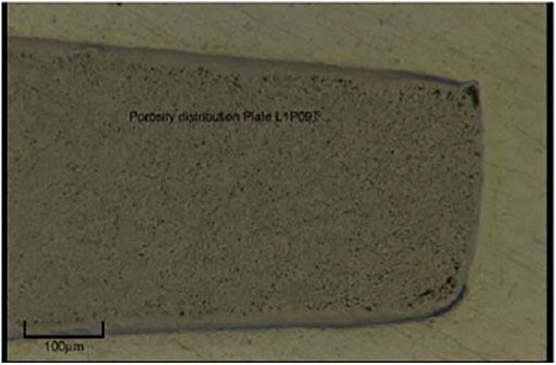
FIGURE 1. Post irradiation section of a UMo fuel meat (Rice, 2010)
Irradiation tests are the direct means to study the in-pile thermal-mechanical behavior of UMo/Zr monolithic fuel element (Perez et al., 2007; Perez et al., 2012). Simultaneously, numerical simulation has become an important and effective mean to study the distribution and evolution laws of in-pile behavior. A number of numerical researches appear on the in-pile behavior of UMo/Al monolithic fuel plate (Miller et al., 2010; Kim and Hofman, 2011; Miller and Ozaltun, 2012; Kong et al., 2018). However, the related numerical simulation researches for UMo/Zr monolithic fuel plates are limited (Zhao et al., 2015). The mesoscale-structure, pore pressure and the macroscale thermal-mechanical behavior should be comprehensively correlated.
In this research, the model of the maximum skeleton stress for the fuel meat is further developed with the effects of bubble distribution pattern considered, which are introduced into the simulation of the thermal-mechanical behavior of the UMo/Zr monolithic fuel plate. The obtained macro-mesoscale mechanical field variables are analyzed.
The Theoretical Models for the Macro-Mesoscale Behavior of U-Mo Fuel Meat
Gas Atom Number in the Gas Bubbles
According to Booth model (Booth, 1957; Cui et al., 2015), the origin grain of the UMo fuel meat could be treated as two parts, including the recrystallization region and the unrecrystallization region, once the recrystallization of fuel meat starts, as shown in Figure 2.
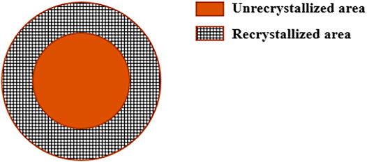
FIGURE 2. The recrystallization region and the unrecrystallization region.
The fission gas atoms in the unrecrystallization region satisfy (Cui et al., 2015):
where
The total number of fission gas atoms in the bubbles of the unrecrystallization region is:
in which
For the recrystallization region, almost all the fission gas atoms will transfer to the intergranular bubbles (Rest, 2005). For each grain, the gas atom number in the intergranular bubbles is:
The number of gas atoms in the gas bubbles per unit volume of the original fuel meat is:
The parameters including N,
In the unrecrystallization area, most of the fission-gas atoms are in the intragranular bubbles or in solution of the fuel matrix. These bubbles are quite small, and the internal pressure will be balanced by the surface tension to affect the stresses of the fuel skeleton slightly. When considering only the gas atoms in the intergranular bubbles, Eq. 2 should be re-described as:
Finally, the number of gas atoms in the intergranular gas bubbles per unit volume of the original fuel meat is given as:
The Inner Pressure of the Gas Bubbles
When the UMo grains are fully recrystallized, the gas bubbles would be almost in a uniform distribution. With the assumption that the gas bubbles are all spherical, the bubble volume fraction of
where
Considering the volume change only results from the irradiation swelling, we have
where
The number of the gas atoms in the equivalent gas bubbles is:
It should be mentioned that when the gas bubbles are large enough, the influence of the surface tension in the bubbles could be ignored. In the unit cell, the gas atoms in the bubbles satisfy the Van der Waals gas-state equation, expressed as
where
Finally, the equivalent inner pressure is described as:
When only considering the influence of the intergranular gas bubbles, the inner pressure can be described as:
Maximum Skeleton Stress of the Porous UMo Fuel Meat
The UMo alloy presents brittle failure after irradiation (Schulthess et al., 2019). For the further research on the brittle failure mechanism of the fuel meat, the maximum tensile stress on the mesoscale should be studied. To consider the influences of the porosity and pore pressure on the maximum skeleton stress, this study assumes that the macroscale first principle stress is along the normal direction of the pore-close-packed section, which is the most dangerous section to initiate cracking. Thus, the largest tensile stress in the fuel skeleton can be obtained. In Refs. (Jian et al., 2019a), (Yan et al., 2019b), the skeleton stresses of FCC (Face Centered Cubic) and SC (Simple Cubic) bubble distribution pattern were respectively presented. However, the chosen section of FCC case was not the pore-close-packed section. In this study, the maximum skeleton stress model will be further developed.
The study of maximum skeleton stress will start from some certain distribution patterns. As shown in Figure 3, the close-packed section of the BCC (Body Centered Cubic) case is the red plane across the center of the gas bubbles.
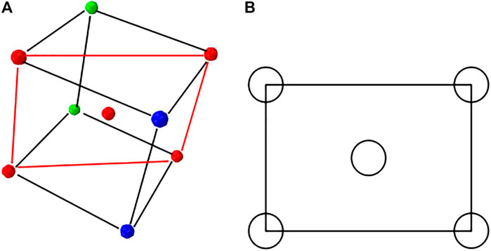
FIGURE 3. (A) BCC arrangement; (B) The pore-close-packed section of the BCC case.
It should be mentioned that the fission-gas swelling contributed by the intergranular gas-bubbles is much larger than the intragranular gas-bubble (Zhao et al., 2016). In this research, the inner pressure of the intergranular gas-bubbles is used in the calculation of the maximum skeleton stress. According to the static equilibrium equation, given as
one can obtain
In the above equations,
For the BCC case, the pore radius r and edge-length a meet
Combining Eqs 18, 19, the maximum skeleton stress of the fuel meat could be obtained as
For some other bubble-distribution patterns, the maximum skeleton-stress models can be similarly derived out, and they could be expressed in a unified form:
where
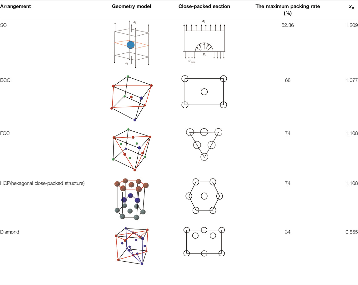
TABLE 1.
According to Eq. 21, the maximum skeleton stress of the fuel meat will be higher with a larger value of
On the assumption that a certain arrangement of the pores meets the conditions below:
1) There are
2) The relative value of the area of the weak section in the cube cross section is S;
3) The number of the pores on the weak section is m.
On the weak section, the static equilibrium equation is shown as below:
The maximum skeleton tensile stress is:
According to Eq. 21, there is:
The relationship among porosity, the radius of the pores r, the numbers of the pores
Finally there is:
The gas pores are randomly distributed in the fuel meat (Gan et al., 2012; Kim et al., 2013a). For a completely random and uniform distribution pattern, the bubble distribution can be regarded as isotropy. The representative volume element can be established as an equivalent sphere containing a spherical bubble (Wei et al., 2019), as shown in Figure 4. The radius of the gas bubble is r, and the radius of the fuel element is a.
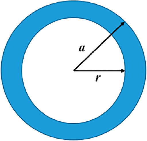
FIGURE 4. The RVE for the random distribution pattern.
The porosity of the RVE is:
The mesoscale skeleton stress can be described as:
which represents that
The gas bubble distributions still have uncertainties, so it is necessary to investigate the effects of bubble distribution patterns.
It is noted that the developed models in this section are suitable for the high burn-up cases.
Finite Element Model
A finite element model is built to simulate the macro-mesoscale in-pile thermal-mechanical behaviors of the U-10Mo/Zr monolithic fuel plate. According to a certain irradiation condition in RERTR-9 (Kim et al., 2013b), the fission rate of the fuel meat is set as (Kong et al., 2018):
where
The fuel meat is considered to be well bonded with the cladding. The geometrical dimension of the plate is
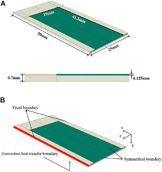
FIGURE 5. (A) Geometry model; (B) Boundary condition.
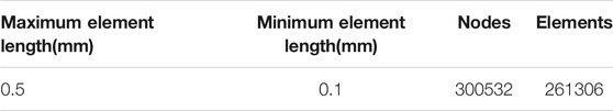
TABLE 2. Mesh parameters
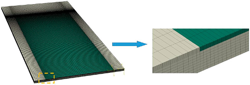
FIGURE 6. Finite element meshes.
As shown in Figure 5B, there is a thermal boundary condition set on the lower surface (the x-z plane), which satisfies
The other surfaces meet the adiabatic boundary condition, which is
Results and Discussion
The Macro-Deformation Fields
The Thickness Increments of the Fuel Meat
As shown in Figure 7, the thickness of the fuel meat increases faster at the side with stronger irradiation and suffering the highest temperature. With increasing the burn-up, the thickness of the fuel meat grows, and finally forms the shape similar as the results of UMo/Al fuel plate in Figure 8B. On the 30th day, the maximum thickness increases by 16.3%, and the average thickness increment per day is 0.543%. From the 30th day to the 90th day, the maximum thickness relative increment reaches 61.02%, and the average thickness increment per day is 0.745%. From the 90th day to the 120th day, the above two value are respectively 85.87 and 0.828%. The increase acceleration stems from the grain recrystallization.
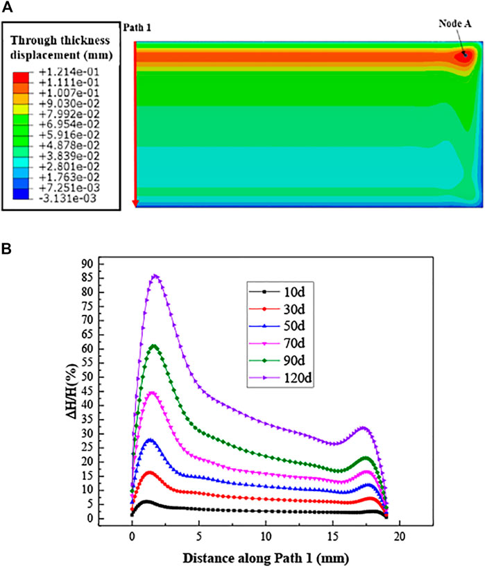
FIGURE 7. (A) The distribution of the thickness displacement of the fuel meat after the 120 days irradiation; (B) the evolution of the thickness along Path 1.
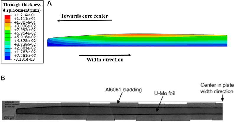
FIGURE 8. (A) The distribution of the thickness displacement of the fuel meat under 120 days irradiation; (B) post irradiation shape of UMo/Al fuel plate (Kim and Hofman, 2011).
The Contributions of Irradiation Swelling and Creep
The distribution of the through-thickness irradiation creep strain can be found in Figure 9. The maximum value occurs at the location near the corner with high irradiation. As shown in Figure 9B, with the influence of irradiation creep, the fuel meat at the edge region tends to flow towards the center, which affects the post-irradiation shape of the fuel meat.
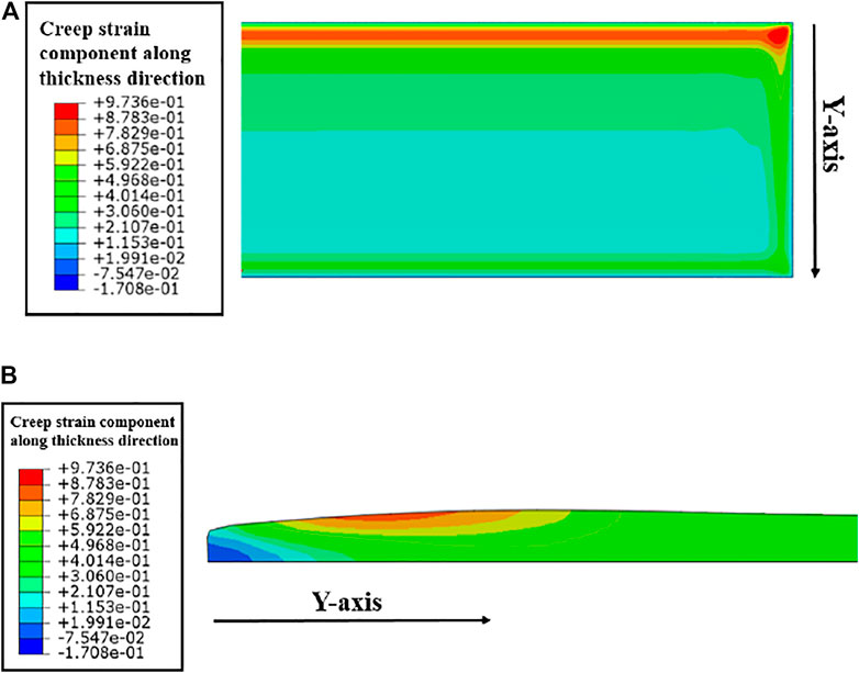
FIGURE 9. (A) The distribution of the through-thickness creep component from the view of plate surface and (B) from the view of cross-section along the plate width.
Figure 10B displays the total irradiation swelling, which basically obeys the same distribution as the fission rate in the width direction, and is uniformly distributed along the length direction, except the small fluctuations near the ends. These fluctuations are attributed to the locally enhanced hydrostatic pressures near the ends, which result in the locally reduced fission gas swelling in Figure 10C. As shown in Figure 10D, the through-thickness strains of irradiation swelling and creep are the dominant contributions of the meat thickness increments. One can see that the irradiation creep strains are much larger than the swelling strains, and the irradiation creep strains determine the post-irradiation shape of the fuel meat. This appearance is consistent with that in Ref. (Jian et al., 2019b).
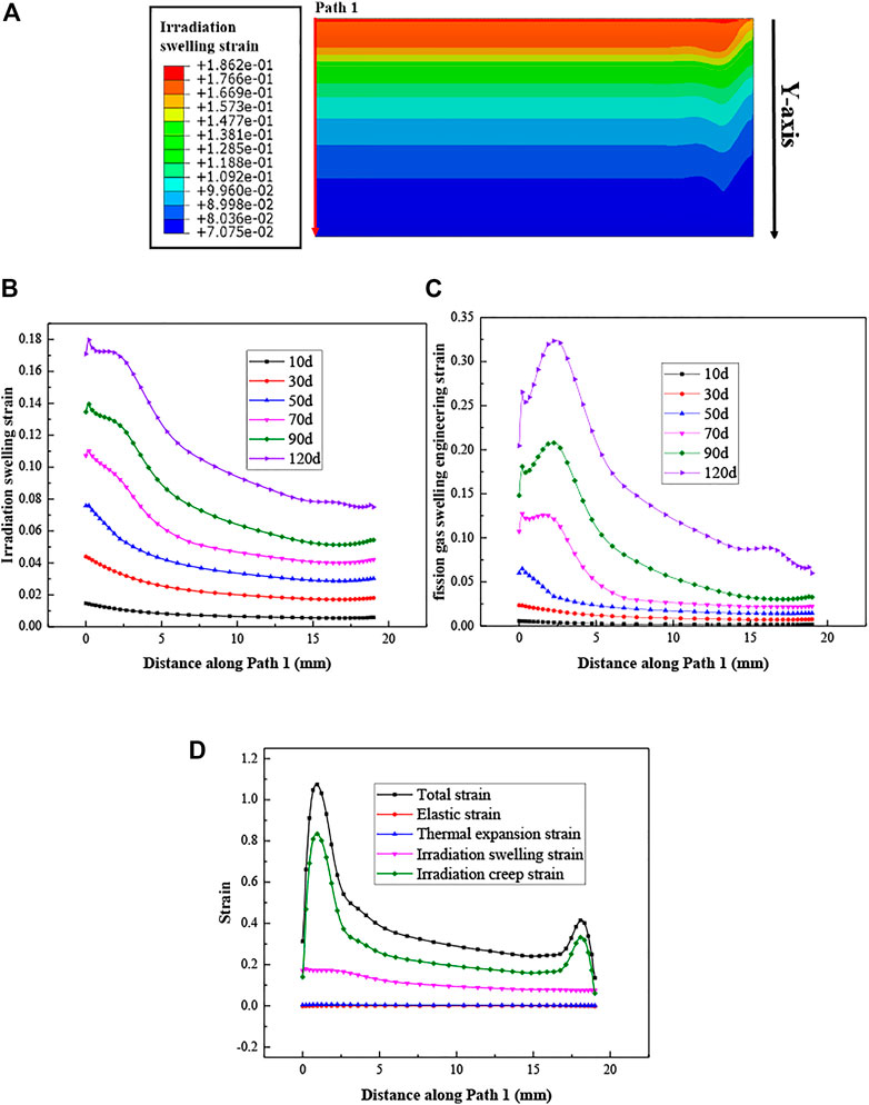
FIGURE 10. (A) The distribution of the thickness displacement of the fuel meat after the 120-days irradiation; (B) Evolution of the total irradiation swelling strain and (C) the fission gas swelling strain along Path 1; (D) Distribution of each strain on the 120th day along Path 1.
The fission gas swelling results in Figure 10C can be explained by the results of the hydrostatic pressures and temperature in Figures 11, 12. After the 120 days irradiation, the hydrostatic pressures are much higher at the edge regions and near the corners, together with locally lowered temperature. There exists the regions with negative hydrostatic pressures, with the distances away from the ends ranged from 2-5 mm, which tend to give rise to the fission gas swelling. From the curves of fission gas swelling in Figure 10C, one can find that the values are the largest at the location that is about 3 mm away from the heavily irradiated end.
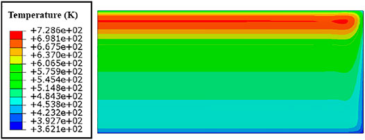
FIGURE 11. Temperature distribution of the fuel meat after 120 days irradiation.
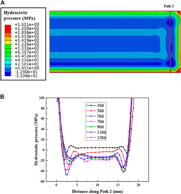
FIGURE 12. (A) Distribution of the hydrostatic pressure (the upper side has a larger fission rate) and (B) evolution of the hydrostatic pressure along Path 2.
The Porosity and Gas-Bubble Inner Pressure
It could be observed from Figure 13A that the gas bubble volume fraction is larger near the side with the strongest irradiation. The porosity here could be up to 20% on the 120th day. As shown in Figure 13C, the porosity near the heavily irradiated end increases faster after the 30th day. It could be seen from Eq. 9 that the porosity is mainly related to the fission gas swelling, thus the distribution and evolution of the porosity in Figure 13 is similar to those of the fission gas swelling.
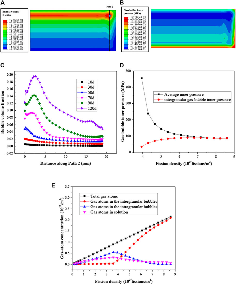
FIGURE 13. (A) Distribution of the porosity; (B) distribution of the gas-bubble inner pressure on the 120th day; (C) evolution of the porosity on Path 2; (D) evolution of the gas-bubble inner pressure at higher burn-up levels; (E) evolution of the gas-atom concentration.
After the recrystallization begins, the evolution of the gas-bubble inner pressure for the blue point in Figure 13A is shown in Figure 13D. This phenomenon was also predicted in Ref. (Jian et al., 2019b). From the 55th day to the 120th day, the pressure decreases by 368.4 MPa. From Figures 13A,B, one can see that the gas-bubble inner pressure is extremely high at the corners and edges of the fuel meat, and the gas-bubble inner pressure is lower at the high-porosity area. As depicted in other researches, when the recrystallization begins, the fission gas swelling rises more quickly (Cui et al., 2015; Robinson et al., 2021). However, the rate of the production of the fission gas atoms does not change (Cui et al., 2015), as shown in Eq. 1). Therefore, the gas atoms number in the bubbles keeps increasing linearly. The bubble inner pressure decreases to match the gas-state equation. The inner pressure of the intergranular bubbles rises with the increase of burn-up, because more gas atoms are released into the intergranular bubbles, as shown in Figure 13E. With the used irradiation-swelling model, most of the gas atoms are predicted to be in the intergranular bubbles, when the recrystallization process is finished. The values of
Macro-Mesoscale Stress Fields
After the 120 days irradiation, the interfacial normal stress, which means the normal stress component on the interface between the fuel meat and cladding, is shown in Figure 14.
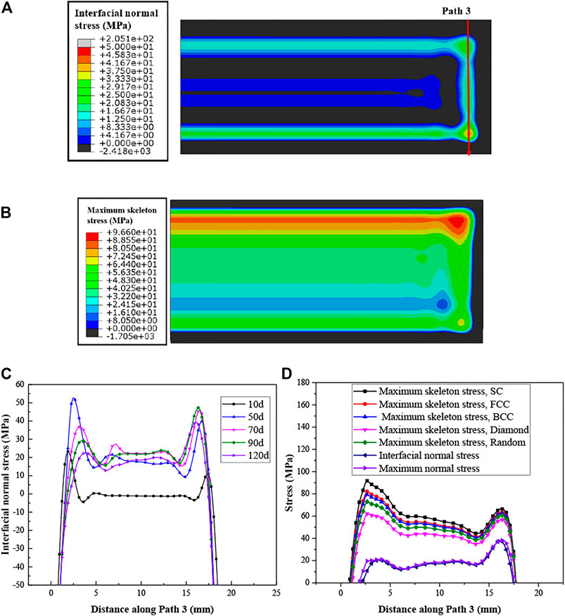
FIGURE 14. (A) Distribution of the interfacial normal stress between the fuel meat and cladding (the upper side has stronger irradiation); (B) Distribution of the maximum skeleton stress in the fuel meat; (C) evolution of the interfacial normal stress along Path 3; (D) Distribution of the maximum skeleton stress under different bubble distribution patterns along Path 3 on the 120th day.
On the interface between the fuel meat and cladding, some areas experience tensile stresses. If the interface strength is weak there, separation could take place during irradiation. On Path 3, the peak tensile stress values locate near the heavily irradiated end, but not just at this end. The peak values rises firstly, and then falls. If the interface strength is high enough, the interface delamination will not occur, and the porous fuel meat is possible to be cracked, as mentioned in the part of Introduction. The cracking of the fuel meat depends on the maximum skeleton stresses.
It could be seen from Figure 14B that there are large values of the maximum skeleton stresses near the meat corner after the 120 days irradiation, which are much higher than the macroscale first principal stresses. The distribution of the maximum skeleton stresses is similar to that of the interfacial normal stress and the first principle stress. However, at the center of the fuel meat/cladding interface, the interfacial normal stress is negative or near zero, while the maximum skeleton stress is up to ∼60 MPa. The tensile skeleton stresses in the fuel meat may cause the cracking of the fuel meat. The macroscale first principal stresses of the fuel meat close to the interface are very similar to the interfacial normal stresses, which implies the corresponding section is vertical to the interface. If the fuel meat fails, the crack plane would be in parallel to the interface of the fuel meat and cladding. The maximum skeleton stress is almost 4–5 times of the macroscale first principal stress. Therefore, the failure prediction of the fuel meat should consider the effect of porosity and bubble inner pressure.
Simultaneously, one can observe from Figure 14D that the maximum skeleton stresses vary with the bubble distribution patterns. When the gas bubbles obey the SC arrangement, the maximum skeleton stress has the largest value, while the diamond arrangement has the least. For the cases of the BCC and FCC arrangements, the peak values are nearly the same, which are a bit lower than that of the SC arrangement, and higher than the random-distribution case. Except for the diamond-pattern case, the peak stress values for the other cases locate near the heavily irradiated edge. The distribution of the maximum skeleton stress for the diamond-pattern case is more like the distribution of the first principle stress, because the influence of the gas-bubble inner pressure is less with smaller
Conclusion
In this study, the theoretical models for the porosity, the gas-bubble inner pressure and the maximum skeleton stress of the fuel meat were further developed, with the effects of the bubble distribution patterns considered. The macro-mesoscale thermal-mechanical behavior of the UMo/Zr monolithic fuel plate were obtained and analyzed, with the new models adopted. The main conclusions are summarized as:
1) The fission gas swelling and porosity of the fuel meat depends on the grain recrystallization process, and the greatly affected by the external hydrostatic pressures. The bubble inner pressure falls quickly after the grain recrystallization begins.
2) The maximum skeleton stresses of the fuel meat may reach ∼4 times of the macroscale first principal stresses, which demonstrates that it is necessary to include the contributions of bubble fraction and pressure in the fuel failure predictions.
3) The arrangements of the gas bubbles in the fuel meat may have an distinct effect on the maximum skeleton stresses. These results of the SC arrangement are the most conservative for the predictions of the porous fuel meat.
In this research, the maximum skeleton stress is based on the assumption of uniformly distributed intergranular gas-bubbles. When the UMo alloy is not fully recrystallized, the intergranular gas-bubbles may not obey the uniform distribution. In the future works, a local porosity model is needed to be established for obtaining more reasonable mesoscale skeleton stresses. Besides, the thermal-mechanical properties of the UMo alloy such as the elastic modulus, the thermal conductivity and the irradiation creep need to be correlated with the porosity. Combined with more experimental data of fission-gas related behavior, a multi-field coupling and multi-scale fracture model for the UMo monolithic fuel plate can be developed in the future, based on the mesoscale skeleton stress model, to predict the fuel fracture and analyze the fracture mechanism.
Indeed, the model for the skeleton stress is developed, based on the mechanistic fission gas-swelling model in the reference, so the precision of the maximum stress is dependent on the reasonability of the adopted gas-swelling model. The current fission gas-swelling model can capture the experimental results of the swelling, which should be further improved to match the experimental data about the bubble density and radius.
Data Availability Statement
The raw data supporting the conclusion of this article will be made available by the authors, without undue reservation.
Author Contributions
XK: Software, Validation, Formal analysis, Investigation, Data Curation, Writing—Original Draft, Visualization XJ: Software, Validation, Investigation, Data Curation, Writing—Original Draft FY: Software, Validation, Formal analysis, Investigation, SD: Conceptualization, Methodology, Software, Resources, Writing—Review & Editing, Supervision, Project administration WL, ZG, CL, YL: Conceptualization, Methodology, Resources, Supervision, Project administration All authors contributed to article revision, read, and approved the submitted version.
Funding
The authors are very grateful for the support of National Natural Science Foundation of China (No. 12132005, 12102094).
Conflict of Interest
The authors declare that the research was conducted in the absence of any commercial or financial relationships that could be construed as a potential conflict of interest.
Publisher’s Note
All claims expressed in this article are solely those of the authors and do not necessarily represent those of their affiliated organizations, or those of the publisher, the editors, and the reviewers. Any product that may be evaluated in this article, or claim that may be made by its manufacturer, is not guaranteed or endorsed by the publisher.
Acknowledgments
The authors are very grateful for the support of the foundation from Science and Technology on Reactor System Design Technology Laboratory.
References
Burkes, D. E., Casella, A. M., Casella, A. J., Buck, E. C., Pool, K. N., MacFarlan, P. J., et al. (2015). Thermal Properties of U-Mo Alloys Irradiated to Moderate Burnup and Power. J. Nucl. Mater. 464, 331–341. doi:10.1016/j.jnucmat.2015.04.040
Cui, Y., Ding, S., Chen, Z., and Huo, Y. (2015). Modifications and Applications of the Mechanistic Gaseous Swelling Model for UMo Fuel. J. Nucl. Mater. 457 (Suppl. C), 157–164. doi:10.1016/j.jnucmat.2014.11.065
Gan, J., Keiser, D. D., Miller, B. D., Robinson, A. B., Jue, J. F., Medvedev, P., et al. (2012). TEM Characterization of U–7Mo/Al–2Si Dispersion Fuel Irradiated to Intermediate and High Fission Densities[J]. J. Nucl. Mater. 424 (1), 43–50. doi:10.1016/j.jnucmat.2012.02.001
Gan, J., Miller, B. D., Keiser, D. D., Jue, J. F., Madden, J. W., Robinson, A. B., et al. (2017). Irradiated Microstructure of U-10Mo Monolithic Fuel Plate at Very High Fission Density. J. Nucl. Mater. 492, 195–203. doi:10.1016/j.jnucmat.2017.05.035
Gong, X., Zhao, Y., and Ding, S. (2014). A New Method to Simulate the Micro-thermo-mechanical Behaviors Evolution in Dispersion Nuclear Fuel Elements. Mech. Mater. 77 (Suppl. C), 14–27. doi:10.1016/j.mechmat.2014.06.004
Gonzalez, A. G., Muñoz, C. A., and Arnaldo, G. J. (2015). Metallographic Study on Alloy Zircaloy-4 of Nuclear Use. Proced. Mater. Sci. 8, 494–501. doi:10.1016/j.mspro.2015.04.101
Holt, R. A., and Causey, A. R. (2004). Volume Conservation during Irradiation Growth of Zr-2.5Nb. J. Nucl. Mater. 335 (3), 529–533. doi:10.1016/j.jnucmat.2004.07.042
Hu, S., Setyawan, W., Joshi, V. V., and Lavender, C. A. (2017). Atomistic Simulations of Thermodynamic Properties of Xe Gas Bubbles in U10Mo Fuels. J. Nucl. Mater. 490, 49–58. doi:10.1016/j.jnucmat.2017.04.016
Jian, X., Kong, X., and Ding, S. (2019). A Mesoscale Stress Model for Irradiated U 10Mo Monolithic Fuels Based on Evolution of Volume Fraction/radius/internal Pressure of Bubbles. Nucl. Eng. Tech. 51 (6), 1575–1588. doi:10.1016/j.net.2019.04.011
Jian, X., Yan, F., Kong, X., and Ding, S. (2019). Effects of U-Mo Irradiation Creep Coefficient on the Mesoscale Mechanical Behavior in U-Mo/Al Monolithic Fuel Plates. Nucl. Mater. Energ. 21, 100706. doi:10.1016/j.nme.2019.100706
Jue, J.-F., Keiser, D. D., Miller, B. D., Madden, J. W., Robinson, A. B., and Rabin, B. H. (2018). Effects of Irradiation on the Interface between U-Mo and Zirconium Diffusion Barrier. J. Nucl. Mater. 499, 567–. doi:10.1016/j.jnucmat.2017.10.072
Kim, Y. S., Hofman, G. L., and Cheon, J. S. (2013). Recrystallization and Fission-Gas-Bubble Swelling of U–Mo Fuel[J]. J. Nucl. Mater. 436 (1), 14–22. doi:10.1016/j.jnucmat.2013.01.291
Kim, Y. S., Hofman, G. L., Cheon, J. S., Robinson, A. B., and Wachs, D. M. (2013). Fission Induced Swelling and Creep of U–Mo alloy Fuel[J]. J. Nucl. Mater. 437 (1), 37–46. doi:10.1016/j.jnucmat.2013.01.346
Kim, Y. S., and Hofman, G. L. (2011). Fission Product Induced Swelling of U–Mo alloy Fuel[J]. J. Nucl. Mater. 419 (1), 291–301. doi:10.1016/j.jnucmat.2011.08.018
Kong, X., Tian, X., Yan, F., Ding, S., Hu, S., and Burkes, D. E. (2018). Thermo-mechanical Behavior Simulation Coupled with the Hydrostatic-pressure-dependent Grain-Scale Fission Gas Swelling Calculation for a Monolithic UMo Fuel Plate under Heterogeneous Neutron Irradiation. Open Eng. 8 (1), 243–260. doi:10.1515/eng-2018-0029
Kong, X., Yang, H., and Ding, S. (2016). Zircaloy Plate Rolling Simulation with an Effective Strain-rate-dependent Stress-Updating Algorithm. Int. J. Nonlinear Sci. Numer. Simulation 17 (2), 113–125. doi:10.1515/ijnsns-2015-0077
Liu, M., and Chen, C. (2015). A Micromechanical Analysis of the Fracture Properties of Saturated Porous media. Int. J. Sol. Structures 63, 32–38. doi:10.1016/j.ijsolstr.2015.02.031
Liu, M., Zhang, Y., Wu, J., Gan, Y., and Chen, C. Q. (2016). Analytical Solutions for Elastic Response of Coated Mesoporous Materials to Pore Pressure. Int. J. Eng. Sci. 107, 68–76. doi:10.1016/j.ijengsci.2016.07.010
Meyer, M. K., Gan, J., Jue, J. F., Keiser, D. D., Perez, E., Robinson, A., et al. (2014). Irradiation Performance of U-Mo Monolithic Fuel. Nucl. Eng. Tech. 46 (2), 169–182. doi:10.5516/net.07.2014.706
Miller, G. K., Burkes, D. E., and Wachs, D. M. (2010). Modeling thermal and Stress Behavior of the Fuel-Clad Interface in Monolithic Fuel Mini-Plates. Mater. Des. 31 (7), 3234–3243. doi:10.1016/j.matdes.2010.02.016
Miller, S. J., and Ozaltun, H. (2012). Evaluation of U10Mo Fuel Plate Irradiation Behavior via Numerical and Experimental Benchmarking. Asme International Mechanical Engineering Congress & Exposition. [C].
Pasqualini, E. E., Robinson, A. B., Porter, D. L., Wachs, D. M., and Finlay, M. R. (2016). Fabrication and Testing of U-7Mo Monolithic Plate Fuel with Zircaloy Cladding. J. Nucl. Mater. 479, 402–410. doi:10.1016/j.jnucmat.2016.07.034
Perez, D. M., Nielsen, J. W., Chang, G. S., and Ro, G. A. (2012). AFIP-7 Irradiation Summary Report[R]. Idaho National Laboratory.
Perez, D. M., Lillo, M. A., Chang, G. S., Roth, G. A., Woolstenhulme, N. E., and Wachs, D. M. (2007). RERTR-6 Irradiation Summary Report[J].
Rest, J. (2005). A Model for the Effect of the Progression of Irradiation-Induced Recrystallization from Initiation to Completion on Swelling of UO 2 and U–10Mo Nuclear Fuels ☆[J]. J. Nucl. Mater. 346 (2), 226–232. doi:10.1016/j.jnucmat.2005.06.012
Robinson, A. B., Williams, W. J., Hanson, W. A., Rabin, B. H., Lybeck, N. J., and Meyer, M. K. (2021). Swelling of U-Mo Monolithic Fuel: Developing a Predictive Swelling Correlation under Research Reactor Conditions. J. Nucl. Mater. 544, 152703. doi:10.1016/j.jnucmat.2020.152703
Rodriguez, P., Krishnan, R., and Sundaram, C. V. (1984). Radiation Effects in Nuclear Reactor Materials-Correlation with Structure. Bull. Mater. Sci. 6 (2), 339–367. doi:10.1007/bf02743907
Rowcliffe, A. F., Mansur, L. K., Hoelzer, D. T., and Nanstad, R. K. (2009). Perspectives on Radiation Effects in Nickel-Base Alloys for Applications in Advanced Reactors. J. Nucl. Mater. 392 (2), 341–352. doi:10.1016/j.jnucmat.2009.03.023
Salvato, D., Leenaers, A., Van den Berghe, S., and Detavernier, C. (2018). Pore Pressure Estimation in Irradiated UMo. J. Nucl. Mater. 510, 472–483. doi:10.1016/j.jnucmat.2018.08.039
Schulthess, J. L., Lloyd, W. R., Rabin, B., Wheeler, K., and Walters, T. W. (2019). Mechanical Properties of Irradiated U Mo alloy Fuel. J. Nucl. Mater. 515, 91–106. doi:10.1016/j.jnucmat.2018.12.025
Snelgrove, J. L., Hofman, G. L., Meyer, M. K., Trybus, C. L., and Wiencek, T. C. (1997). Development of Very-High-Density Low-Enriched-Uranium Fuels. Nucl. Eng. Des. 178 (1), 119–126. doi:10.1016/s0029-5493(97)00217-3
Wei, H., Jian, X., and Ding, S. (2019). A Model of Gas-Induced Effective Expansion Strain for Porous Carbon Materials in Irradiation Environments. J. Nucl. Mater. 515, 338–353. doi:10.1016/j.jnucmat.2018.12.045
Yan, F., Kong, X., Ding, S., He, D. M., Li, Y. M., Chen, P., et al. (2019). Effects of Porous Fuel Structure on the Irradiation-Induced Thermo-Mechanical Coupling Behavior in Monolithic Fuel Plates[J]. Scientia Sinica: Physica, Mechanica et Astronomica 49 (11), 114606. doi:10.1360/sspma2018-00297
Yan, F., Jian, X., and Ding, S. (2019). Effects of UMo Irradiation Creep on the Thermo-Mechanical Behavior in Monolithic UMo/Al Fuel Plates. J. Nucl. Mater. 524, 209–217. doi:10.1016/j.jnucmat.2019.07.006
Zhao, Y., Gong, X., Cui, Y., and Ding, S. (2016). Simulation of the Fission-Induced Swelling and Creep in the CERCER Fuel Pellets. Mater. Des. 89, 183–195. doi:10.1016/j.matdes.2015.09.135
Keywords: UMo/Zr, irradiation-thermal-mechanical behavior, gas-bubble volume fraction, gasbubble inner pressure, skeleton stress
Citation: Kong X, Jian X, Yan F, Li W, Guo Z, Lu C, Ding S and Li Y (2022) Macro-Mesoscale In-Pile Thermal-Mechanical Behavior Simulation of a UMo/Zr Monolithic Fuel Plate. Front. Energy Res. 9:801398. doi: 10.3389/fenrg.2021.801398
Received: 25 October 2021; Accepted: 07 December 2021;
Published: 24 January 2022.
Edited by:
Wenzhong Zhou, Sun Yat-sen University, ChinaReviewed by:
Di Yun, Xi’an Jiaotong University, ChinaJiankai Yu, Massachusetts Institute of Technology, United States
Zhouyu Liu, Xi’an Jiaotong University, China
Copyright © 2022 Kong, Jian, Yan, Li, Guo, Lu, Ding and Li. This is an open-access article distributed under the terms of the Creative Commons Attribution License (CC BY). The use, distribution or reproduction in other forums is permitted, provided the original author(s) and the copyright owner(s) are credited and that the original publication in this journal is cited, in accordance with accepted academic practice. No use, distribution or reproduction is permitted which does not comply with these terms.
*Correspondence: Shurong Ding, ZGluZ3NodXJvbmdAZnVkYW4uZWR1LmNu