 Pan Liu1
 Yuebing Li
- 1State Key Laboratory of Nuclear Power Safety Monitoring Technology and Equipment, China Nuclear Power Engineering Co., Ltd., Shenzhen, China
- 2Institute of Process Equipment and Control Engineering, Zhejiang University of Technology, Hangzhou, China
Nuclear power can be used for power generation, space heating, and other fields, producing a limited level of greenhouse gases and no atmospheric pollutants. However, the safety of nuclear reactors is always a public concern. The reactor pressure vessels (RPVs) play an important role in the safe operation of a nuclear power plant. When a defect is inspected in the RPV, complex analytical evaluation procedures, including fatigue analysis and fracture assessment, are necessary to ensure the structural integrity of the defective component. Based on the RSE-M, a quick evaluation approach for RPVs with defects exceeding acceptance standards is proposed in this work to reduce the computational complexity and analysis time. The flaw evaluation is simplified by adjusting the inspection period based on the analysis of fatigue crack growth. The new method was applied to the RPVs with embedded defects and underclad semi-elliptical defects, respectively. The proposed evaluation approach was verified by the case of a typical RPV cylinder containing an embedded crack, where all possible transients during the operation of nuclear power plants are considered. During the allowable residual life obtained of 5-years, failure would not occur in the defective component via the conventional method, which gives confidence to the availability of the new approach. Consequently, the proposed method can be a valid reference for the structural integrity assessment of nuclear reactor components with defects exceeding acceptance standards.
Introduction
Nuclear energy is widely admitted as a virtually carbon-free energy source and is predicted to provide a major solution to global warming (Apergis et al., 2010; Akhmat and Zaman, 2013). The use of nuclear energy has been paid more attention in recent years, such as electricity (Gao et al., 2013), residential and industrial space heating (El-Genk and Tournier, 2003; Xu et al., 2021), and seawater desalination (Nisan et al., 2003). Consequently, the reliability of the reactor pressure vessel is of great importance because it would directly influence the safety and operation of the nuclear power plant.
During the manufacture and operation of reactor pressure vessels (RPVs) in nuclear power plants, it is difficult to avoid all the defects, which causes potential threats to the structural integrity of RPV. These defects must be detected by nondestructive testing techniques and evaluated according to some relevant standards such as ASME XI (ASME Boiler and Pressure Vessel Code, 2017), RSE-M (RSE-M, 2010), BS 7910 (BS7910, 2019), and R6 (R6, 2019). Some acceptance criteria for RPV defects have been established under conservative assumptions with safety factors. If the defect size is less than the allowable crack size recommended in the corresponding acceptance criterion, the defect can be accepted. Otherwise, it is necessary to implement complex analytical evaluation procedures, including fatigue analysis and fracture assessment, to ensure the structural integrity of RPV until the next inspection period. Massive calculations and much computational time are required in the existing evaluation procedures, which may cause a delay in construction and huge pecuniary loss. Therefore, it is necessary to establish a reasonable and reliable procedure for the rapid assessment of RPV defects exceeding the allowable flaw size in the standards.
Both ASME XI and RSE-M provide in-service inspection criteria and allowable defect sizes of core components, including RPV, nozzle, and pipe. However, the basis of acceptance criteria for defects appears to be ambiguous (Kobayashi and Kashima, 2000). It should be noted that the allowable flaw depths in the current acceptance standards were developed in the 1980s (Maccary and Quinn, 1980). With the development of the fracture mechanics theories and the improvement of the flaw detectability by ultrasonic inspection, the acceptance standards need to be updated. Hasegawa et al. (Hasegawa et al., 1999) established uniform allowable axial defect sizes for pressure pipes composed of moderate toughness materials based on elastic-plastic fracture mechanics. Miyazaki et al. (Miyazaki et al., 2007) proposed a new acceptance standard for class 2 and class 3 austenitic piping based on the acceptance standard for class 1 piping in ASME XI, which was determined by the limit load analysis of circumferential defects with high-stress levels. Further, they derived the permissible sizes for surface defects and embedded defects. Rana et al. (Rana et al., 2010) developed acceptance/rejection limits for seamless, high-pressure gas cylinders by modifying the critical flaw sizes based on the fatigue crack growth analysis.
When the detected cracks exceed the acceptance standards, detailed analytical evaluation is required, including fatigue crack growth analysis and fracture assessment. Chen et al. (Chen et al., 2018) carried out a detailed analysis to obtain the critical crack sizes for RPVs under pressurized thermal shock (PTS) events. Kiminobu (Hojo, 2019) introduced the revised flaw evaluation procedures for cast austenitic stainless steel (CASS) pipe regulated in Japan Society of Mechanical Engineers (JSME). Uddin et al. (Uddin et al., 2021) developed the flaw evaluation procedure for various CASS materials, and the proposed procedure was compared with that in ASME Code. Li et al. (Li et al., 2020) used the failure assessment diagram to evaluate the critical crack size of the RPV model with nozzle corner cracks under transient loading. It can be seen that large amounts of finite elements are demanded to obtain the stress field and temperature field. In addition, most analyses need expert decisions and time, such as level 3 in the failure assessment diagram. During the damage tolerant analysis of cracks, finite element analysis is necessary to calculate the stress distribution or fracture driving forces. Bergant (Bergant et al., 2020) carried out finite element analysis and calculated maximum allowable corner crack sizes in small nozzle process penetrations in the pressure vessel of the small modular reactor CAREM-25 subjected to mechanical and thermal shock loadings during certain operational events. Therefore, it is necessary to develop a new engineering method for quick evaluation of the cracks exceeding the acceptance standards.
Compared with the complicated assessment procedure in the existing standards, some studies have also focused on assessing the defects exceeding the standards and proposed relevant simplified or rapid assessment methods. Kuutti and Oinonen (Kuutti and Oinonen, 2018) proposed a method based on yearly flaw size lines by qualitatively ranking the crack growth potential of different components to rapidly quantify the crack growth rate and remaining life of components. Kashima (Kashima, 2002) proposed a new defect assessment approach for circumferentially surface-cracked nuclear pipe under tensile and bending loads and estimated the allowable crack geometry for continuous plant operations. According to the two load curves based on elastic-plastic fracture mechanics and plastic failure, the fracture stress and fracture criterion can be estimated quickly and conveniently, which has strong applicability in the structural integrity assessment of RPVs.
In this paper, based on the defect acceptance criteria provided in the existing standards, a new quick evaluation method was developed for defects exceeding the acceptance standards by reducing the residual life. Then, the quick evaluation method was applied to the embedded defects and the underclad semi-elliptical defects in RPVs. The residual service life of the defective components was determined and summarized in the figures. Finally, a conventional method used in standards, including the fatigue crack growth analysis and fracture assessment, was performed for RPV with an embedded crack based on linear elastic fracture mechanics. The results show that the quick evaluation procedure is feasible and reliable.
Proposal of a New Quick Evaluation Method
Conventional Evaluation Methods in Standards
The first step in flaw evaluation is the comparison with the allowable crack size. A defect in RPV detected by pre-service or in-service examinations should be enclosed in a bounding rectangle or square to describe its dimensions. In this way, the defect size is compared with the corresponding allowable crack size involved in the acceptance standards. A defect which size does not exceed the allowable flaw size is acceptable for continued service.
If the defect size exceeds the allowable value, the second step in flaw evaluation should be performed. The crack sizes until the end of the evaluation period should be evaluated first. The acceptability of the flaw at the end of the evaluation period is based on fracture analysis. Meanwhile, the interval required for performing an inspection is identified based on the inspection records. Typically, the inspection interval is set as 10 years after the power plant began commercial operations (Cipolla and RAO, 2012).
Allowable Flaw Sizes
The allowable flaw size is the limit of a defect allowed in the component for continued service, which can be found in RSE-M and ASME according to the defect type and material properties. The allowable sizes of embedded defects provided by these two standards for RPV with the thickness of 204 mm are compared in Figure 1. It is shown that the allowable flaw depth raises with the increase of the aspect ratio a/c (where a is the half crack depth and c is the half crack length, as shown in Figure 2) in both standards. The figure also indicates that the values obtained by ASME XI and RSE-M are close, while the allowable flaw sizes in RSE-M are less conservative for long cracks and more conservative for short cracks.
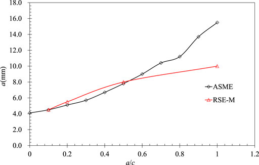
FIGURE 1. Allowable embedded crack sizes in RPV given by ASME and RSE-M.
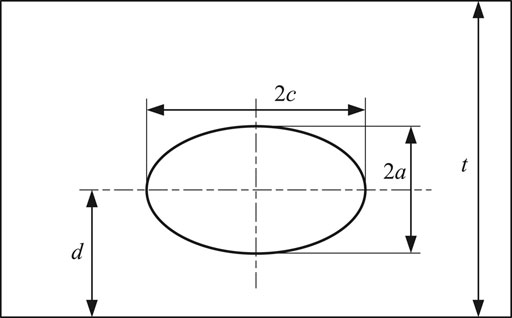
FIGURE 2. Geometries for embedded cracks.
Detailed Flaw Evaluation
The defect that size exceeds its allowable flaw size may be evaluated by analytical procedures. The fatigue growth analysis should be performed applying the appropriate growth rate of fatigue crack to determine the maximum potential of fatigue crack growth value under the normal operational condition. If the analytical evaluation for the defect meets the acceptance criteria, the defective component is acceptable for continued service without a repair or replacement. Note that the acceptance criteria are usually developed based on the fracture analysis by considering the proper safety factors (Faidy, 2019).
In ASME XI, the evaluation procedure for ferritic vessels is based on the linear elastic fracture mechanics. The exceed-allowed defect is acceptable if the applied stress intensity factor (SIF) KI for defect depth af and length lf at the end of the evaluation period satisfies the acceptance criteria required in the standard. For normal and upset conditions, KI < KIC/
In RSE-M, the temperature range and fracture mode for RPV components are provided in the acceptance criteria based on the linear elastic fracture mechanic or elastic-plastic fracture mechanic (Faidy, 2003). The component containing a planar defect will be acceptable for continued service until the end of the assessment period if there is no fracture risk or plastic instability risk after calculating changes in the defect size by fatigue analysis. The fracture risk or plastic instability risk is judged by comparing the crack driving force with the corresponding material fracture toughness. The safety margins used in fracture assessment according to the RSE-M are summarized in Table 1.
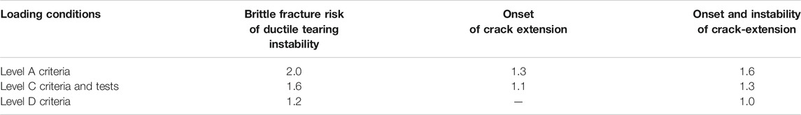
TABLE 1. Safety margins derived from RSE-M.
The New Quick Evaluation Method: Residual Life Evaluation
The fatigue growth analysis for the defective component is performed first when the flaw size exceeds the allowable flaw size. Based on the requirements in RSE-M, the conventional fatigue growth analysis and fracture assessment are complex and time-consuming. Consequently, a simplified method is developed in this section, and the results of different defect types are established in Section Analysis of the New Method Applied to Different Defect Types based on this new method.
The fatigue crack growth rate da/dN is based on the Paris formula (Paris and Erdogan, 1963) and can be expressed as follows:
where C and n are the parameters governing the fatigue crack growth rate. The equivalent SIF range ΔKeff can be determined considering the effect of load ration R and plastic correction,
The function f(R) is related to the effect of the environment, such as in water or air. The SIF range modified by plasticity, ΔKcp, can be defined as follows:
where αcp is the plastic correction coefficient, ΔK is the SIF range at the crack tip, Y is the geometric correction coefficient, Δσ is the stress range, and a is the crack depth.
Integrating the Eq. (1), the final crack size af for an initial crack size a0 with cycle N can be calculated as follows:
The predicted life for the crack growth from a0 to af can be obtained as follows:
From Eq. (5), it is found that different values of initial crack size a0 provide different residual lifes N when the final crack size af is given. For certain material properties and load conditions that the values of C, n, and Δσ are identical, the life ratio N1/N2 for the initial cracks with depths a01 and a02 depends on their plastic correction coefficient, geometric correction coefficient, and fatigue crack growth rate. The plastic correction of SIF is usually ignored in fatigue crack growth, and the geometric correction factor of SIF increases with the increase in crack size. Consequently, the maximum value of Y during the crack growth process is adopted for getting conservative results.
The final crack size af for an initial crack size a0 with a given life N can be simplified as follows:
where ΔKe, equal to Δσ
The geometric influence coefficient is ignored in ΔKe. Therefore, the geometric influence coefficient of af is used to replace the geometric influence coefficient of the initial crack for obtaining a more conservative life. Besides, it is assumed that the loading conditions are identical in the operational process, which means that the stress range Δσ is unchanged for any defect. It can be considered that the parameter Q in ratios N1/N2 can be canceled for a given af. Therefore, the ratio N1/N2 only relates to the fatigue parameter b.
Based on the assumption mentioned above, the quality categorization assessment for the welded structures is recommended by the BS7910. Accordingly, the residual life evaluation can be determined for different initial cracks under a certain final crack depth, supposing that the load transients in a nuclear power plant are unchanged every year. When the defect size exceeds the allowable flaw size, the service life is reduced, and the inspection period is adjusted without detailed evaluation procedures.
The predicted life ratio N1/N2 for the crack growth from the initial crack depth a01 and a02 to the final crack depth af can be described as
In Eq. (7), the a01 can be taken as the allowable crack depths specified in acceptance standards, ensuring that the defective components are reliable during the inspection interval of 10 years (N1 = 10). The a02 can be valued as the detected crack depth exceeding the allowable crack size specified in standards. If the allowable crack depth a01 and the residual life N1 are determined, the residual life N2 for the a02 can be determined with the final crack depth af. Note that the final crack size af can be derived from the acceptable crack size recommended in the rapid fracture assessment criteria in RSE-M.
To sum up, the quick evaluation method can be performed for the continued operation of the defective components as follows. Once a detected crack depth a02 exceeds the allowable flaw size a01 specified in standards, the allowable residual life N2 can be determined with the final crack depth af and the fatigue parameter b based on Eqn. (7). Then, the inspection period of this exceed-allowed defective component should be reduced from N1 to N2 without any detailed evaluation.
Analysis of the New Method Applied to Different Defect Types
The new method proposed in Section Proposal of a New Quick Evaluation Method is applied to different defect types commonly exist in RPV cylinders. The allowable residual service years of the exceed-allowed defects are obtained and summarized in figures, which can be applied in engineering directly.
The Results of the Establishment of the New Method
Type 1: Embedded Defect in RPV
For embedded defects in RPV cylinders, the acceptable crack size of 20.0 mm is adopted according to the rapid fracture assessment criteria in RSE-M. The values of the parameter n are usually equal to 8, 3.73, and 1.4 as given in RSE-M. Based on the Eq. (7), the life ratios for defective RPVs (allowable crack size a01 = 6.5mm, detected crack size a02 = 8.0 mm) with different final crack sizes af are plotted in Figure 3. The figure indicates that the life ratio N1/N2 decreases with the increase in the final crack size, but it remains unchanged when af exceeds 40.0 mm. Consequently, af = 20.0 mm is taken as a conservative value in the analysis. It can also be seen that the parameter n influences the allowable residual life more obviously than the af. The life ratio (N1/N2) increases significantly as the parameter n increases, which means the residual life N2 decreases with the same N1.
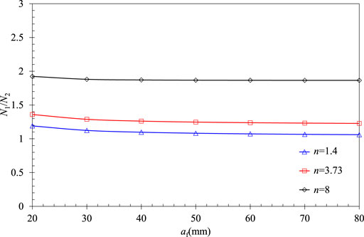
FIGURE 3. Life ratios for the embedded crack with a01 = 6.5 mm, a02 = 8.0 mm.
Generally, the fatigue crack growth parameter n for steel in the Paris equation is valued at about 3.0. Therefore, n = 3.73 is adopted to determine the allowable residual life. The allowable flaw sizes a01 for embedded flawed RPVs with different aspect ratios a/c are obtained by RSE-M. The residual service years for different crack aspect ratios and detected crack sizes are obtained by Eq. (7), and the results are shown in Figure 4.
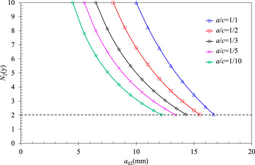
FIGURE 4. Residual service lifes of different crack aspect ratios for embedded cracks in RPV cylinders.
For the crack with its size exceeding the allowable flaw size a01 recommended in RSE-M, the residual life can be checked in Figure 4 according to its aspect ratio a/c and detected crack size a02. Then, the defective RPV is considered acceptable in the residual service life without complex flaw evaluation procedures. In this way, it is ensured that the residual life evaluation method for the defect is consistent with the allowable crack suggested in RSE-M. Note that the minimum value of the allowable residual life is limited to 2 years, considering the reload cycle of the nuclear power plant to avoid the fatigue crack growth becoming uncontrollable. The embedded crack sizes with the allowable residual life of 2 years, also defined as the maximum sizes for the defect that can use the quick evaluation, are summarized in Table 2.
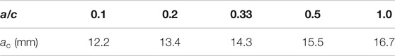
TABLE 2. Acceptable embedded crack sizes with the allowable residual life of 2 years.
Type 2: Underclad Semi-elliptical Defect
The allowable flaw sizes for underclad semi-elliptical defects (as shown in Figure 5) are provided in ASME, while the RSE-M only gives the corresponding sizes for surface semi-elliptical defects. The corresponding allowable flaw sizes recommended in these two standards are close according to the comparison shown in Figure 6. However, the fracture assessment is required to prove that the allowable flaw sizes for the surface semi-elliptical defects in RSE-M are compatible with the underclad semi-elliptical defects.
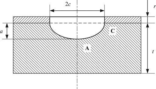
FIGURE 5. Geometries for underclad semi-elliptical cracks.
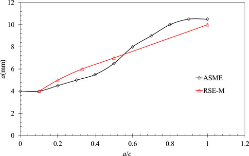
FIGURE 6. Allowable embedded crack sizes given by ASME and RSE-M.
The coefficients of the stress intensity factor given by RSE-M can be used for the underclad semi-elliptical defect when the ratio of the crack depth to the thickness of the cladding is less than 4. Consequently, the crack depth considered is taken as 28 mm when the cladding thickness is 7 mm, and the aspect ratio is 0.1 for the fracture assessment. The corrected stress intensity factor at the crack tip is compared to the fracture toughness in Figure 7. The results show that the fracture will not occur in the defective component under the most dangerous loading condition, considering the safety margin. Therefore, the allowable flaw sizes for surface semi-elliptical defects are acceptable for underclad semi-elliptical defects.
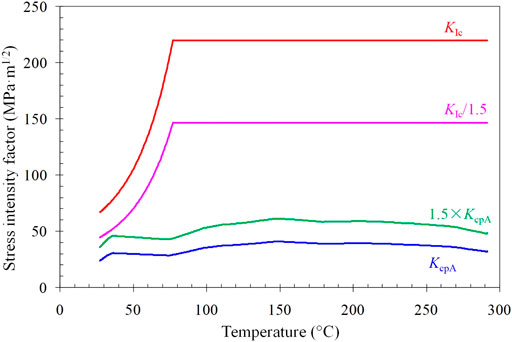
FIGURE 7. Stress intensity factors of underclad semi-elliptical defects (a = 28.0 mm, c = 280.0 mm) under the most dangerous condition.
For underclad semi-elliptical defect with a01 = 6.0 mm, a02 = 8.0 mm in RPV cylinders, the life ratio for different final crack size af based on the Eq. (7) is plotted in Figure 8. The same trend is shown as that for the embedded defect.
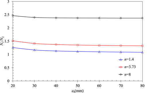
FIGURE 8. Life ratios for embedded cracks with a01 = 6.0 mm, a02 = 8.0 mm.
Similarly, n = 3.73 is used to determine the allowable residual life. The allowable flaw sizes for the surface semi-elliptical defects with different aspect ratios, a01, can be obtained by RSE-M. The residual service years for different crack aspect ratios and detected crack depths based on Eq. (7) are plotted in Figure 9. For an exceed-allowed defect, the residual life can be checked in Figure 9 according to its aspect ratio and detected crack depth. The RPV with that defect is considered safe during the residual service life N2 without flaw evaluation. The minimum value of the allowable residual life is also taken as 2 years. The acceptable underclad semi-elliptical crack depths with a residual life of 2 years are summarized in Table 3.
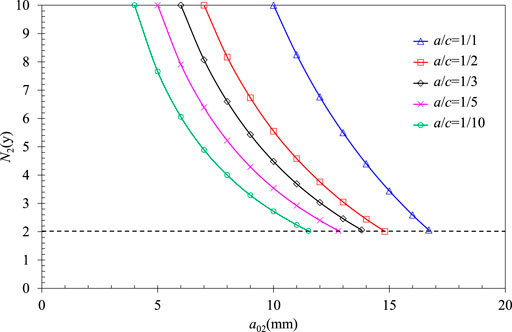
FIGURE 9. Residual service lifes of different crack aspect ratios for underclad semi-elliptical cracks in RPV cylinders.
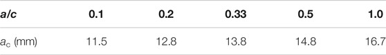
TABLE 3. Acceptable underclad semi-elliptical crack depths with the allowable residual life of 2 years.
Comparison, Discussion and Verification
To verify the feasibility of the proposed quick evaluation, a typical RPV cylinder with an embedded defect is considered. Fatigue crack growth analysis and fracture assessment are performed to prove that the RPV cylinder with defects exceeding the allowable crack sizes in acceptance standards can operate safely during the residual life obtained by quick evaluation.
Considering the typical RPV geometry specified in standard CPR1000, the inner radius Ri is 1994.5 mm, the cladding thickness tc is 7 mm, and the thickness of base material t is 204 mm. The initial embedded crack is taken with half-depth a = 10.0 mm and the half-length c = 30.0 mm. The distance from the center of the crack to the wall d is 109 mm.
The 16MND5 steel is used for base metal, and the 309L/308L stainless steel is applied for cladding in the analysis for the flawed RPV cylinders. The thermophysical and mechanical properties of the materials used are listed in Tables 4, 5 according to appendix Z in RSE-M, including thermal conductivity λ, specific heat capacity C, thermal expansion coefficient α, and elastic modulus E. The fatigue crack growth rates for 16MND5 used in the pressurized water reactor (PWR) are shown in Table 6 according to Appendix 5.6 in RSE-M.
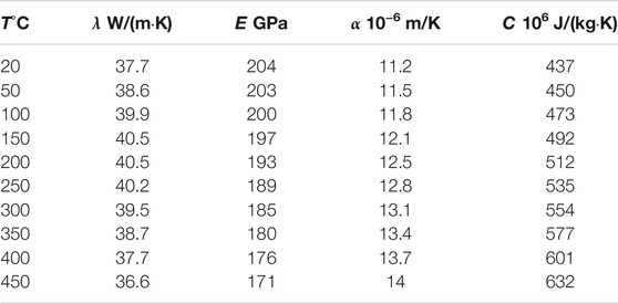
TABLE 4. Material properties of 16MnD5.
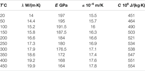
TABLE 5. Material properties of cladding.
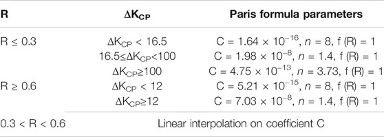
TABLE 6. Fatigue crack growth rate parameters for materials used in PWR.
In the fatigue crack growth analysis, 38 typical load transients that potentially appear in the RPVs during the operation of nuclear power plants are considered. As shown in Figure 10, the internal pressure and temperature under the typical load transients change with time.
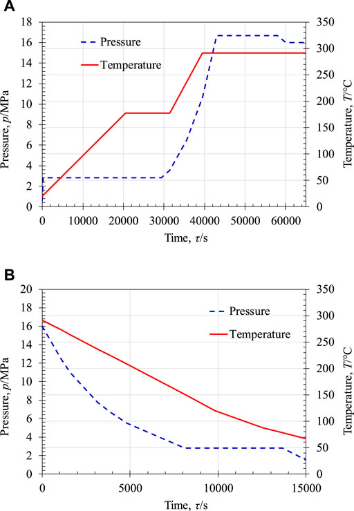
FIGURE 10. Typical transients with the change of temperature and pressure: (A) TR1-1; (B) TR2.
Compared with the allowable flaw size in the existing requirements of RSE-M, the crack size exceeds the acceptance standard. According to the quick evaluation procedure, the allowable residual life of the defective component is 5 years as shown in Figure 4.
The fatigue crack growth analysis and fracture assessment are used to verify the reliability of the quick evaluation procedure proposed in this paper. According to fatigue crack growth analysis, the final crack sizes of the defect in 5 and 10 years are a = 10.007 mm, c = 30.001 mm and a = 10.014 mm, c = 30.001 mm, respectively. The extension of the defect is less than 1 mm in 10 years, which is negligible compared to the initial crack size. Besides, the final size of the crack is only a = 10.057 mm, c = 30.004 mm even in 40 years.
The comparison of the corrected stress intensity factor under condition TR1-1 obtained in fracture assessment to the fracture toughness is shown in Figure 11A. The corrected stress intensity factor is much lower than the fracture toughness of the material considering the safety margin, which implies that the crack is acceptable within the allowable residual service life.
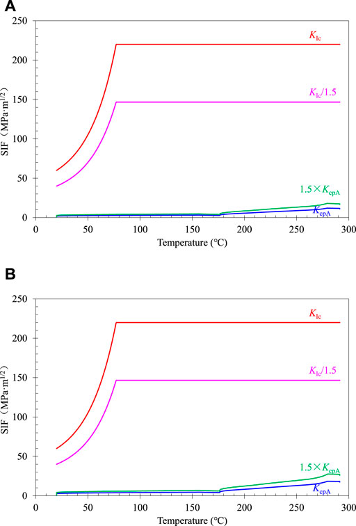
FIGURE 11. Stress intensity factors of embedded crack under TR1-1 condition: (A) a = 10.057 mm, c = 30.004 mm; (B) a = 20.0 mm, c = 200.0 mm.
The case of RPV with a final crack half-depth of 20.0 mm and crack aspect ratio of 1/10 is considered to illustrate the conservatism of the assumed final crack size and the results are shown in Figure 11B. Considering the safety margin, the corrected stress intensity factor of the crack tip is still lower than the material fracture toughness. Therefore, the defect is acceptable within the allowable residual service life. In other words, the RPV cylinders with the postulated crack would not rupture under the transient condition even if the crack half-depth reaches 20.0 mm.
Conclusion
A quick evaluation approach was proposed for defects in RPVs which exceed the allowable flaw size. The new method reduces the residual service life for the flawed RPV based on fatigue crack growth analysis. Then, the new approach was applied to the embedded defects and the underclad semi-elliptical defects, respectively. The proposed new evaluation approach was verified by a typical RPV cylinder containing an embedded crack considering all possible transients during the operation of nuclear power plants. The main results of the study are summarized as follows.
1) The allowable flaw sizes for RPV (t = 204 mm) in ASME XI are generally close to those in RSE-M. For short cracks, the allowable flaw sizes in RSE-M are more conservative (a/c→1) than ASME XI. When the crack sizes exceed the allowable flaw sizes, the new method can be adopted by reducing the residual life of the RPV from 10 years.
2) The results of the residual life for the embedded defects and the underclad semi-elliptical defects were established and plotted in figures. The figures of the residual life can be directly used in quick engineering evaluation when a defect size exceeds the corresponding allowable crack size specified in RSE-M. The allowable residual life was lower than the initial inspection period of 10 years but more than 2 years according to the reload cycle of the nuclear power plant.
3) For an embedded crack with the size exceeding the allowable value, the fatigue crack growth analysis and the fracture assessment were performed. The results show that the fracture would not occur in the defective component during the residual life obtained by the fast evaluation. Consequently, applying the quick evaluation procedure for an exceed-allowed defect is reliable and available.
Data Availability Statement
The raw data supporting the conclusion of this article will be made available by the authors, without undue reservation.
Author Contributions
PL contributed to conception and analysis, YL contributed to the first draft of the manuscript; TJ contributed to design and proof reading; DW contributed to proof reading.
Funding
This research was funded by National Natural Science Foundation of China, Grant Number 51605435. All sources of funding received for the research have been submitted.
Conflict of Interest
PL, YL, TJ, and DW were employed by China Nuclear Power Engineering Co., Ltd.
The remaining author declares that the research was conducted in the absence of any commercial or financial relationships that could be construed as a potential conflict of interest.
Publisher’s Note
All claims expressed in this article are solely those of the authors and do not necessarily represent those of their affiliated organizations, or those of the publisher, the editors and the reviewers. Any product that may be evaluated in this article, or claim that may be made by its manufacturer, is not guaranteed or endorsed by the publisher.
References
Akhmat, G., and Zaman, K. (2013). Nuclear Energy Consumption, Commercial Energy Consumption and Economic Growth in South Asia: Bootstrap Panel Causality Test. Renew. Sustainable Energ. Rev. 25, 552–559. doi:10.1016/j.rser.2013.05.019
Apergis, N., Payne, J. E., Menyah, K., and Wolde-Rufael, Y. (2010). On the Causal Dynamics between Emissions, Nuclear Energy, Renewable Energy, and Economic Growth. Ecol. Econ. 69 (11), 2255–2260. doi:10.1016/j.ecolecon.2010.06.014
ASME Boiler and Pressure Vessel Code (2017). Section XI, Rules for Inservice Inspection of Nuclear Power Plant Components. New York, United States: ASME.
Bergant, M. A., Yawny, A. A., and Perez Ipiña, J. E. (2020). Damage Tolerant Analysis of Corner Cracks in Small Nozzle Process Penetration of the CAREM-25 Reactor Pressure Vessel. Int. J. Press. Vessels Piping 180, 104036. doi:10.1016/j.ijpvp.2019.104036
BS7910 (2019). Guide to Methods for Assessing the Acceptability of Flaws in Metallic Structures. London, United Kingdom: British Standards Institution.
Chen, M., Yu, W., Qian, G., Shi, J., Cao, Y., and Yu, Y. (2018). Crack Initiation, Arrest and Tearing Assessments of a RPV Subjected to PTS Events. Ann. Nucl. Energ. 116, 143–151. doi:10.1016/j.anucene.2018.01.032
Cipolla, R. C. (2012). “Section XI Flaw Acceptance Criteria and Evaluation Using Code Procedures,” in Companion Guide to the ASME Boiler & Pressure Vessel Code. Editor K. R. RAO (New York: ASME, Three Park Avenue).
El-Genk, M. S., and Tournier, J.-M. P. (2003). Analyses of Static Energy Conversion Systems for Small Nuclear Power Plants. Prog. Nucl. Energ. 42 (3), 283–310. doi:10.1016/s0149-1970(03)90001-1
Faidy, C. (2019). “ASME XI–RSE-M: General Comparison of Flaw Evaluation Rules,” in ASME Pressure Vessels and Piping Conference (San Antonio, Texas, USA: ASME).
Faidy, C. (2003). “General Presentation of French Codified Flaw Evaluation Procedure: RSE-M,” in ASME Pressure Vessels and Piping Conference (Cleveland, Ohio, USA: ASME). doi:10.1115/pvp2003-2024
Gao, J., Nelson, R., and Zhang, L. (2013). Substitution in the Electric Power Industry: An Interregional Comparison in the Eastern US. Energ. Econ. 40, 316–325. doi:10.1016/j.eneco.2013.07.011
Hasegawa, K., Yanagida, N., Kanno, S., Honjin, M., and Kobayashi, H. (1999). Allowable Sizes of Axial Flaws in Pressurized Pipes Made of Moderate Toughness Materials. Int. J. Press. Vessels Pip. 76 (6), 1999. doi:10.1016/s0308-0161(99)00003-4
Hojo, K. (2019). “Introduction of CASS Pipe Flaw Evaluation of JSME Rules on Fitness for Service,” in ASME Pressure Vessels and Piping Conference (San Antonio, Texas, USA: ASME).
Kashima, K. (2002). Flaw Evaluation of Japanese Carbon Steel Piping by Load Curve Approach. Nucl. Eng. Des. 212, 243–251. doi:10.1016/s0029-5493(01)00490-3
Kobayashi, H., and Kashima, K. (2000). Overview of JSME Flaw Evaluation Code for Nuclear Power Plants. Int. J. Press. Vessels Pip. 77 (14), 937–944. doi:10.1016/s0308-0161(01)00016-3
Kuutti, J., and Oinonen, A. (2018). “Comparison of ASME XI and BS7910 Allowable Surface Flaw Size Evaluation Procedures in Piping Components,” in ASME Pressure Vessels and Piping Conference (Prague, Czech Republic: ASME).
Li, Y., Jin, T., Wang, Z., and Wang, D. (2020). Engineering Critical Assessment of RPV with Nozzle Corner Cracks under Pressurized thermal Shocks. Nucl. Eng. Technology 52, 2638–2651. doi:10.1016/j.net.2020.04.019
Maccary, R. R., and Quinn, J. R. (1980). Nondestructive Examination Acceptance Standards Technical Basis and Development of Boiler and Pressure Vessel Code. in ASME Section XI. Division 1. Palo Alto, CA: Electric Power Research Institute. EPRI NP-1406-SR.
Miyazaki, K., Hasegawa, K., Miura, N., Kashima, K., and Scarth, D. A. (2007). “Technical Basis of Proposed New Acceptance Standards for Class 1, 2 and 3 Piping,” in ASME Pressure Vessels and Piping Conference (San Antonio, Texas, USA: ASME). doi:10.1115/pvp2007-26124
Nisan, S., Caruso, G., Humphries, J. R., Mini, G., Naviglio, A., Bielak, B., et al. (2003). Sea-water Desalination with Nuclear and Other Energy Sources: the EURODESAL Project. Nucl. Eng. Des. 221 (1), 251–275. doi:10.1016/s0029-5493(02)00337-0
Paris, P., and Erdogan, F. (1963). A Critical Analysis of Crack Propagation Laws. J. Basic Eng. 85 (4), 528–533. doi:10.1115/1.3656900
R6 (2019). Assessment of the Integrity of Structures Containing Defects. in Revision 4. Amendment 12. Gloucester, UK: EDF Energy Nuclear Generation Ltd.
Rana, M. D., Smith, J. H., and Holroyd, H. (2010). Technical Basis for Acceptance/Rejection Criteria for Flaws in High Pressure Gas cylinder. J. Press. Vessel Technol. 132 (6), 061102. doi:10.1115/1.4001657
Uddin, M., Sallaberry, C., and Wilkowski, G. (2021). Flaw Evaluation Procedure for Cast Austenitic Stainless-Steel Materials Using a Newly Developed Statistical thermal Aging Model. J. Press. Vessel Technol. 143 (5), 051504. doi:10.1115/1.4050222
Keywords: quick evaluation approach, nuclear reactor, allowable crack size, fatigue crack growth, space heating
Citation: Liu P, Li Y, Jin T and Wang D (2021) Quick Evaluation Method for Defect Exceeding the Allowable Flaw Size in Pressure Vessel of Nuclear Reactor for Power Plant and Space Heating. Front. Energy Res. 9:796340. doi: 10.3389/fenrg.2021.796340
Received: 16 October 2021; Accepted: 03 November 2021;
Published: 29 November 2021.
Edited by:
Ning Mao, The University of Tokyo, JapanReviewed by:
Song Wei, Xuzhou University of Technology, ChinaXiaowei Wang, Nanjing Tech University, China
Copyright © 2021 Liu, Li, Jin and Wang. This is an open-access article distributed under the terms of the Creative Commons Attribution License (CC BY). The use, distribution or reproduction in other forums is permitted, provided the original author(s) and the copyright owner(s) are credited and that the original publication in this journal is cited, in accordance with accepted academic practice. No use, distribution or reproduction is permitted which does not comply with these terms.
*Correspondence: Yuebing Li, eWJsaUB6anV0LmVkdS5jbg==