 Lin Feng1
 Yang Qiang
- 1National Engineering Laboratory for Marine and Ocean Engineering Power System—Gas Turbine Lab of Marine Engineering, Harbin Marine Boiler and Turbine Research Institute, Harbin, China
- 2College of Power and Energy Engineering, Harbin Engineering University, Harbin, China
To research the fuel-switching rules for gas turbine dual-fuel combustor, the effects of fuel change rate, fuel compensation rate, permissible fluctuation limit of outlet temperature, and fuel matching on the fuel-switching performance were studied experimentally by using a real dual-fuel gas turbine combustor. The experimental results show that increasing fuel change rate can reduce fuel-switching time, but the influence of fuel viscosity and evaporative atomization combustion hysteresis leads to the increase of outlet temperature amplitude fluctuation. The fuel compensation rate corresponds to the optimal solution for this combustion chamber; when the fuel change rate decreases, the optimal fuel compensation coefficient will be increase. Meanwhile, by increasing the allowable fluctuation range of outlet temperature and reducing the difference of calorific value of natural gas and diesel, the fuel-switching time can be effectively reduced, and the fuel-switching stability can be improved.
Introduction
With the development of The Times, the engine has new requirements for fuel adaptability. Jatropha oil (Hashimoto et al., 2014), CME (canola methyl ester), DME (dimethyl ether, CH3OCH3) (Lee and Yoon, 2012), and other alternative fuel (Nascimento et al., 2008; Erazo et al., 2010; Jiang and Agrawal, 2014; Li et al., 2019) have received much development and attention. Fuel adaptability has also led to the development of dual-fuel engines (Korakianitis et al., 2011; Lounici et al., 2014; Yang et al., 2014; Sun et al., 2015). As most important component of the dual-fuel gas turbine, the research of dual-fuel combustors focuses on the performance of different fuels and the dynamic dual-fuel switching process; the dual-fuel combustor design objective is to organize the combustion field in the same structure under the condition of single combustion and mixed combustion and realize the stable fuel-switching (Chong et al., 2020).
According to the classification of switching time, dual-fuel switching technology can be divided into stable fuel-switching technology and fast fuel-switching technology. Among them, the stable fuel-switching technology is not sensitive to the time requirement of the gas turbine fuel-switching process, and the key point is to ensure that the performance of the combustion chamber can meet the design requirements during the whole process of fuel-switching, which is difficult to meet the needs of emergencies in actual engineering (Agwu and Valera-Medina, 2020). Fast fuel-switching technology is mainly used to solve the shortage of stable fuel-switching technology and ensure the short fuel-switching time under the premise of continuous and stable operation of the engine. As a non-steady working process of the combustion chamber, the main problems of fast fuel-switching technology are as follows: When the gas turbine is switching between different fuels fastly, the flame in the combustion chamber may be unstable due to the mismatch of the different fuels, leading to ablation of turbine blades or dual-fuel nozzles in the combustion chamber. Sometimes, this situation can also result in combustion chamber blowout or overheating. Therefore, how to shorten the fast fuel-switching time while maintaining the fixed position of flame (or the average temperature at the exit of the combustion chamber) and the stability of the flame (the dynamic pressure value in the combustion chamber) is the key of the research on the fast fuel-switching of the dual fuels combustor.
Around this goal, related scholars and units have also carried out research in different directions. In terms of development of dual-fuel research, structural characteristics and performance indexes of dual-fuel combustors in various manufacturers was introduced (Rok̸ke et al., 2003), and development direction of dual-fuel combustors was indicated. In terms of the simulation of dual-fuel combustor, RANS method was adopted to carry out relevant calculation and analysis for dual-fuel combustor, and a reasonable calculation method of dual-fuel cannular combustor was obtained (Zheng et al., 2010); the simplified mechanism of ammonia/methane co-firing mixing reaction is given (Xiao et al., 2017), which can effectively guide the numerical simulation of combustion chamber. In terms of experimental research, dual-fuel comparison tests were carried out on the MHPS FT8 combustion chamber, and test results show that the combustion chamber performance characteristics are similar under different fuels, but the combustion stability will change to a certain extent during the fuel-switching process (Fox and Schlein, 1990). Dual-fuel load performance tests were carried out on the Siemens SGT750 gas turbine combustor; the results show that the liquid fuel injection atomization and the change of the calorific value of gas fuel on the performance of dual-fuel combustor is the key direction of dual-fuel combustor research at present (Lindman et al., 2014; Lindman et al., 2017). Dual-fuel load performance tests were also carried out on the 4.2 MW Micro-gas turbine. The test results show that the lean flame stability margin using LBTU (gasifier generated low heating value) gas was more than adequate in relation to load change and fuel changeover requirements. The exhaust gas temperature overall and radial distribution factors have better performance than diesel when using LBTU (Al-Shaikhly et al., 1994), and similar studies are available in the literature (Liu and Sanderson, 2013; Mordaunt and Pierce, 2014).
In general, because fuel-switching involves key equipment selection, control strategy, and user requirements and some other requirements limitations, theoretical calculation and numerical simulation have both limitations. In order to research the influence of relevant parameters on the combustion chamber fuel-switching performance, a type of gas turbine dual-fuel combustion chamber is used to carry out fast fuel-switching test using natural gas and diesel fuel.
Research Hardware
The research object of this paper is a countercurrent annular dual-fuel combustion chamber and it uses diesel and natural gas as fuel. As shown in Figure 1, there are 16 liners arranged in an annular way; one row of main combustion holes and one row of mixing holes are arranged on the wall of each liner. Both sides of the liner is provided with a flame crossover tube, and liner cooling is used the film structure.
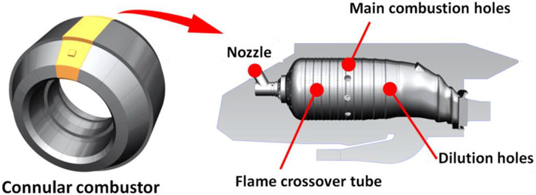
FIGURE 1. Schematic view of dual-fuel combustor structure.
The dual-fuel nozzle structure is shown in Figure 2. The liquid fuel path is located at the center of the nozzle, which adopts the air-assisted atomization structure. The gas fuel path is located in the outer ring of the nozzle, and the injection rules such as injection cone angle and injection velocity are simulated by referring to the liquid fuel atomization.
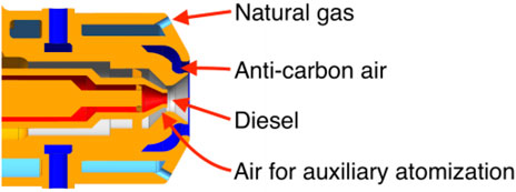
FIGURE 2. Dual fuel nozzle structure scheme.
Test Facility and Method
Test Facility
The test facility is composed of air system, dual-fuel system, ignition system, test device, cooling water system, gas analysis system, exhaust system, measurement system, and control system. The overall appearance of the test facility can be seen in Figure 3.
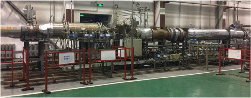
FIGURE 3. Photograph of the experimental system.
During the test, compressed air enters the test combustion chamber to participate in the combustion, and the high-temperature flue gas after combustion leaves the combustion chamber and enters the exhaust system. The exhaust pipe is cooled by the cooling water, and the high-temperature flue gas is cooled into the exhaust tower and discharged to the atmosphere. The starting ignition system is independently supplied with diesel or natural gas fuel and equipped with an igniter for combustion chamber ignition. The fuel system is divided into natural gas channel and diesel channel, through their respective solenoid valve and pressure regulating valve to transport and regulate fuel. The measurement and control system is responsible for regulating and monitoring the state of the system and is also responsible for measuring the fuel, airflow, temperature, and pressure parameters.
The test device is shown in Figure 4. The single-tube molded combustion test device designed to meet the test requirements consists of the test section, the exit measurement section, and the exit transition section. To monitor the inlet and outlet conditions of the combustion chamber, the installation seat of total temperature, total pressure, and static pressure measuring points is arranged at the inlet of the test section, and the installation seat of the outlet temperature thermocouple is arranged at the measurement section. There are 25 thermocouples used to measure the outlet temperature distribution and calculate the OTDF (outlet temperature distribution factor) in this location. The sides of the test device shell are respectively arranged with the igniter equipment seat. Its front end is connected with the air inlet pipe through a connecting flange. Its back end is connected with the outlet measurement section and the transition section in turn, and the transition section is connected with the exhaust pipe.
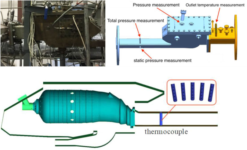
FIGURE 4. Schematic diagram of the modular combustion test device.
Test Method
Due to the short-time mixed combustion of the combustion chamber during fuel-switching, testing under rated conditions may result in combustion chamber flameout or overtemperature.
To study the rule of fuel-switching and ensure safety, the fuel-switching test was modeled at 0.8Ne, and the inlet air temperature of the combustion chamber was set as the atmospheric ambient temperature. The air and fuel parameters used in the test can be seen in Table 1. In the test, to verify the influence of different natural gas calorific value on fuel-switching, N2 with a volume fraction of 8% was injected into natural gas I and renamed natural gas II.
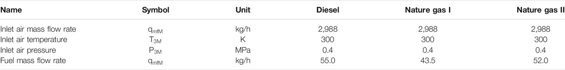
TABLE 1. Design parameters schedule of the single combustor for test.
The fuel-switching test has a combination of multiple parameter changes, which can be seen in Table 2. To facilitate the comparative analysis of the fuel-switching time and the change of combustion chamber performance, the test method of changing one of the items and keeping the rest unchanged was adopted.
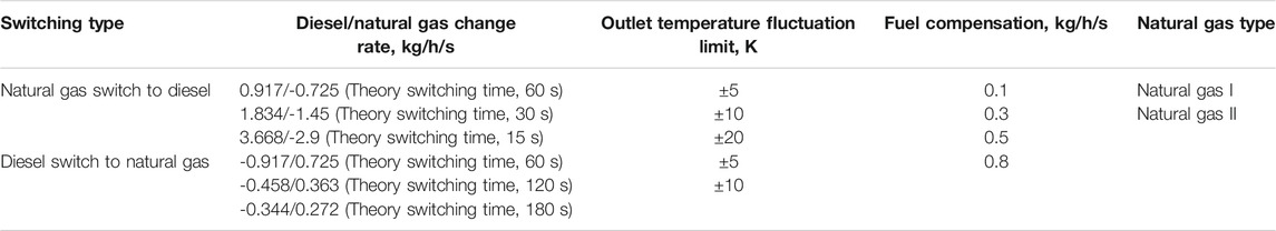
TABLE 2. Content and scheme combination of dual fuel switch test.
In the fuel-switching process, the fuel mass flow rate is set according to the average temperature at the exit of the combustion chamber to remain unchanged, that is, the calorific value of fuel input of the combustion chamber remains unchanged during the fuel switching process:
where
In Table 2, the rate of fuel change the amount of modulated fuel divided by the set-theoretical switching time at a fuel change rate of 0.8Ne. The fuel-switching progress adopts V-type steady-state regulation. The logical diagram is shown in Figure 5. The fuel compensation coefficient is also a kind of fuel change rate, which is mainly used to correct the fuel change rate when the combustion chamber exit temperature is not stable.
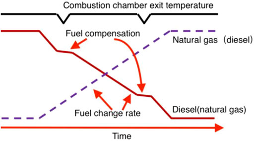
FIGURE 5. Schematic diagram of dual-fuel switching regulation.
Results and Discussion
Rate of Fuel Change
The fuel-switching test was carried out 6 times by changing the rate of fuel/natural gas change. Experiments 1–3 test the switch natural gas-to-diesel, and experiments 4–6 test the switch diesel-to-natural gas. The fuel-switching test scheme is shown in Table 3. During the switching process, the real switching time is shown in Figure 6; the variation of exit temperature, natural gas flow rate, diesel flow rate, dynamic pressure, and OTDF value can be seen in Figure 7 during the test.
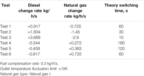
TABLE 3. Fuel change rate test program.
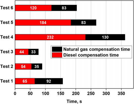
FIGURE 6. Effects of different fuel change rates on real switching time.
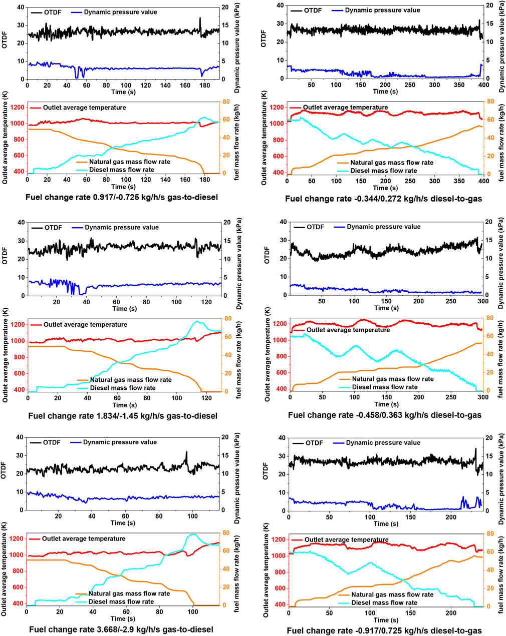
FIGURE 7. Combustion chamber performance when fuel change rate changes.
For the exit temperature of the combustion chamber, the larger fuel change rate will lead to the larger fluctuation range and lower frequency of the exit temperature. As for the OTDF value, it changes with the average temperature at the exit of the combustion chamber. When the temperature increases, the OTDF also increases.
The reason for this phenomenon is that during the fuel-switching process, the flame length in the combustion chamber fluctuates with the fuel amount due to the constant airflow and the unstable fuel amount. The higher internal combustion amount at local time points will inevitably lead to the deterioration of temperature distribution. For this type of combustion chamber, when the gas outlet temperature is increased by 10K, the increased range of OTDF is 1.45–1.93%.
For the combustion chamber pressure fluctuation, the switching process is not greater than the design value of 4 kPa; When diesel oil switch to natural gas, the pressure fluctuation value shows a slight upward trend in the early stage of fuel-switching, and gradually decreases in the later stage. In general, the pressure fluctuation measured at the main combustion hole of the combustion chamber has little relationship with the fuel change rate, and there is no obvious trend of change.
In order to keep the combustion chamber outlet temperature stable, it is necessary to make fuel compensation during fuel-switching. When diesel compensation is used in the switching process, the largely fuel quantity fluctuation causes the outlet temperature of the combustion chamber to fluctuate greatly. In addition, the diesel fuel compensation process takes longer time than the natural gas compensation process in the fuel-switching process; we also find that the fuel flow at the completion of the switching process is far greater than the design value. The reason is mainly due to the viscosity of diesel and its atomization evaporation process. The response time of the outlet temperature of the combustion chamber has a certain lag when using diesel compensation. It also led to a cyclical oscillation and, in the late switch, caused overshoot and extended the fuel-switching time. We can see that the performance is very obvious in the process of diesel switch to natural gas.
In terms of fuel-switching time, with the increase of fuel change rate, the switching time decreases, which is consistent with the theoretical analysis. However, the actual fuel-switching time of the 6 tests was much longer than the theoretical fuel-switching time, and the time of gas-to-diesel was much lower than that of diesel-to-gas. This reason was also related to the fuel used in fuel compensation, which was consistent with the above reasons.
Fuel Compensation
The fuel-switching test was carried out 8 times by changing different fuel compensation amount in the fuel-switching process. Experiments 1–4 test the switch natural gas-to-diesel, and experiments 5–8 test the switch diesel-to-natural gas. The fuel compensation test scheme is shown in Table 4. During the switching process, the influence of fuel compensation amount on switching time is shown in Figure 8; the variation of exit temperature, natural gas flow rate, diesel flow rate, dynamic pressure, and OTDF value can be seen in Figure 9.
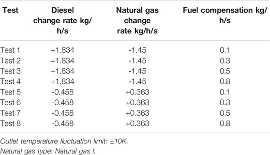
TABLE 4. Fuel compensation coefficient test program.
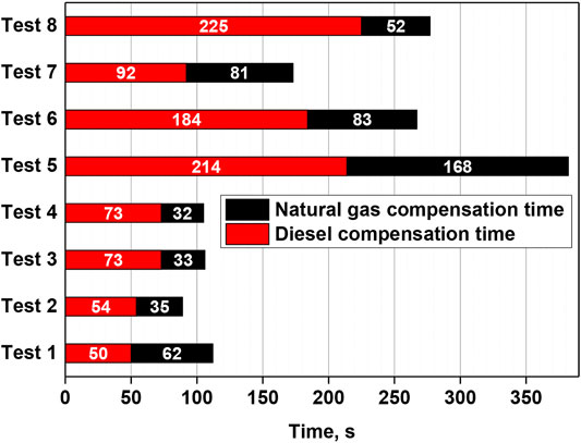
FIGURE 8. Effects of different fuel compensation coefficient on switching time.
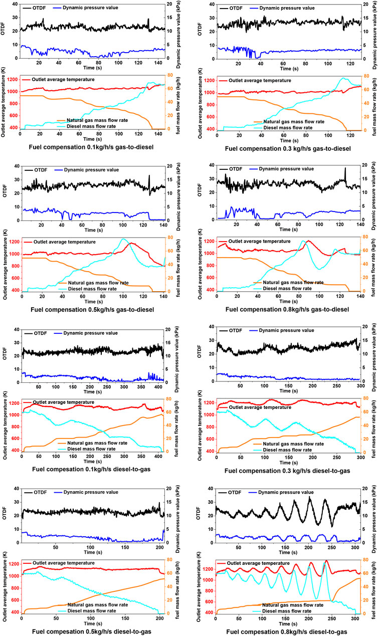
FIGURE 9. Performance when fuel compensation coefficient changes.
The fuel compensation can also be considered as a kind of fuel change rate regulation in essence. Its difference is the regulation target and regulation range. The rate of fuel change reflects the range of fuel quantity change in the overall fuel-switching process, and the fuel compensation reflects the amplitude limit of fuel quantity change at local time points in the fuel-switching process. The experimental results show that the fuel compensation affects the temperature fluctuation at the outlet of the fuel combustion chamber and fuel-switching time.
We can see from the test data that there is an optimal fuel compensation amount corresponding to the shortest fuel switching time. The fuel-switching time is the shortest when the fuel compensation amount is 0.3 kg/h/s for gas-to-diesel. In the reverse fuel-switching progress, the value is 0.5 kg/h/s. The optimal value of the fuel compensation amount in different fuel-switching processes should be related to the setting of theoretical switching time or fuel change rate. From the test results, the smaller fuel change rate corresponds to a larger value of the optimal compensation coefficient.
At the same time, we can also see from the test results that the fuel-switching time decreases with the increase of fuel compensation amount when the fuel compensation amount is less than the optimal point, and the outlet temperature stability is basically the same. However, when the fuel compensation amount is larger than or equal to the optimal point, the exit temperature of the combustion chamber fluctuates greatly, which is similar to the phenomenon and reasons when the fuel change rate is too large in the above section. When the combustion chamber uses diesel fuel for fuel compensation, the delay of outlet temperature response will still lead to the diesel’s flow far beyond the theoretical value, and the restriction of outlet temperature will make the fuel flow adjust to another direction. The cross influence of the two factors will lead to the large fluctuations of the combustion chamber outlet temperature. It can be seen that the fuel compensation amount has a great correlation with the fuel change rate, and there is a more appropriate numerical range under different theoretical switching time.
Limit of Outlet Temperature Fluctuation
The fuel-switching test was carried out 5 times by changing different outlet temperature fluctuation limit in the fuel-switching process. Experiments 1–3 test the switch natural gas-to-diesel, and experiments 4–5 test the switch diesel-to-natural gas. The limit outlet temperature fluctuation test scheme is shown in Table 5. During the switching process, the influence of outlet temperature fluctuation limit on switching time is shown in Figure 10; the variation of exit temperature, natural gas flow rate, diesel flow rate, dynamic pressure, and OTDF value can be seen in Figure 11.
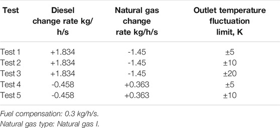
TABLE 5. Limit outlet temperature fluctuation program.
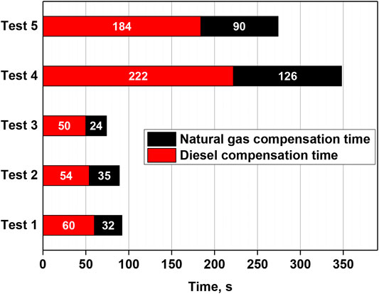
FIGURE 10. Effects of different temperature fluctuation limitation on switching time.
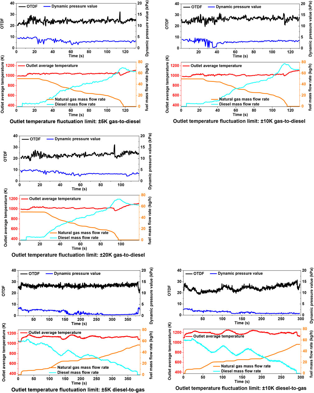
FIGURE 11. Performance when temperature fluctuation limitation of outlet changes.
The limit range of combustion chamber exit temperature fluctuation affects the completion time of fuel-switching and the actual fluctuation of combustion chamber exit temperature. When the limit range of combustion chamber outlet temperature fluctuation is narrower, the compensation times will be increased, so that the fuel-switching time will be prolonged, but the volatility of combustion chamber outlet temperature will be more stable.
For dual-fuel combustion chamber, the limit range of outlet temperature fluctuation in the test essentially reflects the variation of gas turbine power. This variation is determined by the actual engineering load requirements. It can be seen that, in order to reduce fuel-switching time, the limit range of temperature fluctuation or the variation range of gas turbine power should be as large as possible within the permitted value.
Fuel Calorific Value Change Matching
The fuel-switching test was carried out 4 times by changing different natural gas type in the fuel-switching process. Experiments 1–2 test the switch natural gas-to-diesel, and experiments 3–4 test the switch diesel-to-natural gas. The different natural gas type test scheme is shown in Table 6. During the switching process, the influence of natural gas type on switching time is shown in Figure 12; the variation of exit temperature, natural gas flow rate, diesel flow rate, dynamic pressure, and OTDF value can be seen in Figure 13.
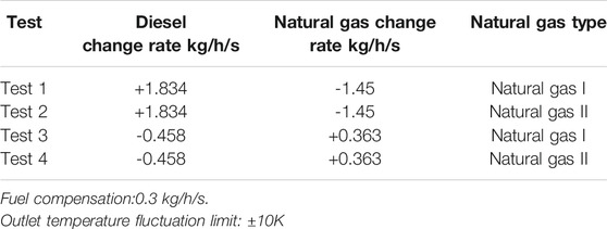
TABLE 6. Fuel change matching test program.
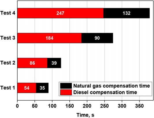
FIGURE 12. Effect of fuel change on switching parameters.
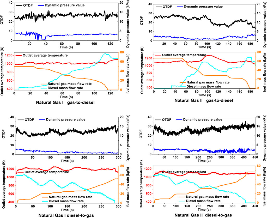
FIGURE 13. Combustion chamber performance when fuel changes.
The test results show that the fuel-switching performance when using natural gas I are better than natural gas II whatever gas-to-diesel or diesel-to-gas fuel-switching process. The reason is that the calorific value of natural gas I is closer to diesel fuel than natural gas II. Better fuel matching (referred to the calorific value of liquid fuel and gas fuel close to each other) is more favorable for dual-fuel combustion chamber switching.
Due to the limitation of the test conditions, more natural gas fuels with different calorific values and different components could not be compared, but it is easy to infer that the specified fuel-switching time must limit the range of fuel calorific value for dual-fuel combustors. Due to the difference of calorific value and components of different fuels, the practical use situation must be considered in the design of dual-fuel combustion chamber.
Conclusion
The fuel-switching performance test of the dual-fuel combustion chamber was carried out on the combustion test facility. The main work and conclusions are as follows:
1) In the fuel-switching test process of the dual fuel combustion chamber, the flame length or OTDF fluctuates just because the unstable fuel quantity and the constant airflow. The instantaneous mismatch between fuel and air flow is the main reason for the fluctuation of outlet temperature.
2) The amount of fuel compensation has a great correlation with the rate of fuel change, and there is a suitable range under different theoretical switching times. For this type of combustion chamber, the optimal fuel compensation is 0.3 kg/h/s when natural gas switches to diesel, and 0.5 kg/h/s when diesel switches to natural gas.
3) The narrower the limit range of combustion chamber outlet temperature fluctuation, the more compensation times will result in the longer fuel-switching time, but the combustion chamber outlet temperature will be more stable.
4) Fuel calorific value difference affects fuel switching time. Lower calorific value difference between gas fuel and liquid fuel will reduce fuel switching time.
Data Availability Statement
The raw data supporting the conclusions of this article will be made available by the authors, without undue reservation.
Author Contributions
LF and YG: data curation, writing original draft preparation, and experiment operating. RJ-h and LX: writing, reviewing and editing, validation. LM-j and LY-j: supervision and funding acquisition.
Conflict of Interest
The authors declare that the research was conducted in the absence of any commercial or financial relationships that could be construed as a potential conflict of interest.
Publisher’s Note
All claims expressed in this article are solely those of the authors and do not necessarily represent those of their affiliated organizations, or those of the publisher, the editors and the reviewers. Any product that may be evaluated in this article, or claim that may be made by its manufacturer, is not guaranteed or endorsed by the publisher.
References
Agwu, O., and Valera-Medina, A. (2020). Diesel/syngas Co-combustion in a Swirl-Stabilised Gas Turbine Combustor. Int. J. Thermofluids 3-4, 100026. doi:10.1016/j.ijft.2020.100026
Al-Shaikhly, A. F., Mina, T. I., and Neergaard, M. O. (1994). “Development of a Dual Fuel LBTU Gas/Diesel Burning Combustion System for a 4.2 MW Gas Turbine,” in ASME 1994 International Gas Turbine and Aeroengine Congress and Exposition (New York, NY: American Society of Mechanical Engineers). doi:10.1115/94-gt-438
Chong, C. T., Chiong, M.-C., Ng, J.-H., Tran, M.-V., Valera-Medina, A., Józsa, V., et al. (2020). Dual-fuel Operation of Biodiesel and Natural Gas in a Model Gas Turbine Combustor. Energy Fuels 34 (3), 3788–3796. doi:10.1021/acs.energyfuels.9b04371
Erazo, J. A., Parthasarathy, R., and Gollahalli, S. (2010). Atomization and Combustion of Canola Methyl Ester Biofuel spray. Fuel 89 (12), 3735–3741. doi:10.1016/j.fuel.2010.07.022
Fox, T. G., and Schlein, B. C. (1990). Full Annular Rig Development of the FT8 Gas Turbine Combustor. J. Eng. Gas Turbines Power 114 (1), 27–32. doi:10.1115/90-gt-029
Hashimoto, N., Nishida, H., and Ozawa, Y. (2014). Fundamental Combustion Characteristics of Jatropha Oil as Alternative Fuel for Gas Turbines. Fuel 126. doi:10.1016/j.fuel.2014.02.057
Jiang, L., and Agrawal, A. K. (2014). Combustion of Straight Glycerol With/without Methane Using a Fuel-Flexible, Low-Emissions Burner. Fuel 136, 177–184. doi:10.1016/j.fuel.2014.07.027
Korakianitis, T., Namasivayam, A. M., and Crookes, R. J. (2011). Diesel and Rapeseed Methyl Ester (RME) Pilot Fuels for Hydrogen and Natural Gas Dual-Fuel Combustion in Compression-Ignition Engines. Fuel 90 (7), 2384–2395. doi:10.1016/j.fuel.2011.03.005
Lee, M. C., and Yoon, Y. (2012). Development of a Gas Turbine Fuel Nozzle for DME and a Design Method Thereof. Fuel 102, 823–830. doi:10.1016/j.fuel.2012.05.017
Li, S., Zhang, S., Zhou, H., and Ren, Z. (2019). Analysis of Air-Staged Combustion of NH3/CH4 Mixture with Low NOx Emission at Gas Turbine Conditions in Model Combustors. Fuel 237, 50–59. doi:10.1016/j.fuel.2018.09.131
Lindman, O., Andersson, M., Bonaldo, A., Larsson, A., Janczewski, J., and Persson, M. (2017). “SGT-750 Fuel Flexibility: Engine and Rig Tests,” in ASME Turbo Expo 2017: Turbomachinery Technical Conference and Exposition. American Society of Mechanical Engineers (Charlotte, NC: American Society of Mechanical Engineers), V04ATA031–V04AT04A. doi:10.1115/gt2017-63412
Lindman, O., Andersson, M., Persson, M., and Munktell, E. (2014). “Development of a Liquid Fuel Combustion System for SGT-750,” in ASME Turbo Expo 2014: Turbine Technical Conference and Exposition (Düsseldorf, Germany: American Society of Mechanical Engineers), V04ATA022. doi:10.1115/gt2014-25380
Liu, K., and Sanderson, V. (2013). The Influence of Changes in Fuel Calorific Value to Combustion Performance for Siemens SGT-300 Dry Low Emission Combustion System. Fuel 103 (264), 239–246. doi:10.1016/j.fuel.2012.07.068
Lounici, M. S., Loubar, K., Tarabet, L., Balistrou, M., Niculescu, D.-C., and Tazerout, M. (2014). Towards Improvement of Natural Gas-Diesel Dual Fuel Mode: An Experimental Investigation on Performance and Exhaust Emissions. Energy 64, 200–211. doi:10.1016/j.energy.2013.10.091
Mordaunt, C. J., and Pierce, W. C. (2014). Design and Preliminary Results of an Atmospheric-Pressure Model Gas Turbine Combustor Utilizing Varying CO2 Doping Concentration in CH4 to Emulate Biogas Combustion. Fuel 124 (15), 258–268. doi:10.1016/j.fuel.2014.01.097
Nascimento, M. A. R., Lora, E. S., Corrêa, P. S. P., Andrade, R. V., Rendon, M. A., Venturini, O. J., et al. (2008). Biodiesel Fuel in Diesel Micro-turbine Engines: Modelling and Experimental Evaluation. Energy 33 (2), 233–240. doi:10.1016/j.energy.2007.07.014
Rok̸ke, P. E., Hustad, J. E., Ro̸kke, N. A., and Svendsgaard, O. B. (2003). “Technology Update on Gas Turbine Dual Fuel, Dry Low Emission Combustion Systems,” in ASME Turbo Expo 2003, collocated with the 2003 International Joint Power Generation Conference (Atlanta, GA: American Society of Mechanical Engineers), 97–107.
Sun, L., Liu, Y., Zeng, K., Yang, R., and Hang, Z. (2015). Combustion Performance and Stability of a Dual-Fuel Diesel-Natural-Gas Engine. Proc. Inst. Mech. Eng. D: J. Automobile Eng. 229 (2), 235–246. doi:10.1177/0954407014537814
Xiao, H., Howard, M. S., Valera-Medina, A., Dooley, S., and Bowen, P. (2017). Reduced Chemical Mechanisms for Ammonia/Methane Co-firing for Gas Turbine Applications. Energ. Proced. 105, 1483–1488. doi:10.1016/j.egypro.2017.03.441
Yang, B., Wei, X., Xi, C., Liu, Y., Zeng, K., and Lai, M.-C. (2014). Experimental Study of the Effects of Natural Gas Injection Timing on the Combustion Performance and Emissions of a Turbocharged Common Rail Dual-Fuel Engine. Energ. Convers. Manag. 87, 297–304. doi:10.1016/j.enconman.2014.07.030
Keywords: gas turbine, combustion chamber, dual-fuel, fuel switch, experimental
Citation: Feng L, Qiang Y, Xiao L, Ming-jia L, Jun-hui R and Ya-jun L (2022) Experimental Study on Fuel-Switching of Dual-Fuel Gas Turbine Combustor. Front. Energy Res. 9:796220. doi: 10.3389/fenrg.2021.796220
Received: 16 October 2021; Accepted: 29 November 2021;
Published: 23 February 2022.
Edited by:
Lei Luo, Harbin Institute of Technology, ChinaReviewed by:
Aiguo Liu, Shenyang Aerospace University, ChinaBing Ge, Shanghai Jiaotong University, China
Copyright © 2022 Feng, Qiang, Xiao, Ming-jia, Jun-hui and Ya-jun. This is an open-access article distributed under the terms of the Creative Commons Attribution License (CC BY). The use, distribution or reproduction in other forums is permitted, provided the original author(s) and the copyright owner(s) are credited and that the original publication in this journal is cited, in accordance with accepted academic practice. No use, distribution or reproduction is permitted which does not comply with these terms.
*Correspondence: Yang Qiang, eWFuZ3FpYW5ndHVyYmluZUAxNjMuY29t